EP1928043B1 - Wiederaufladbare Lithiumbatterie und Separator dafür - Google Patents
Wiederaufladbare Lithiumbatterie und Separator dafür Download PDFInfo
- Publication number
- EP1928043B1 EP1928043B1 EP07121766A EP07121766A EP1928043B1 EP 1928043 B1 EP1928043 B1 EP 1928043B1 EP 07121766 A EP07121766 A EP 07121766A EP 07121766 A EP07121766 A EP 07121766A EP 1928043 B1 EP1928043 B1 EP 1928043B1
- Authority
- EP
- European Patent Office
- Prior art keywords
- separator
- rechargeable battery
- lithium rechargeable
- battery
- negative electrode
- Prior art date
- Legal status (The legal status is an assumption and is not a legal conclusion. Google has not performed a legal analysis and makes no representation as to the accuracy of the status listed.)
- Active
Links
Images
Classifications
-
- H—ELECTRICITY
- H01—ELECTRIC ELEMENTS
- H01M—PROCESSES OR MEANS, e.g. BATTERIES, FOR THE DIRECT CONVERSION OF CHEMICAL ENERGY INTO ELECTRICAL ENERGY
- H01M50/00—Constructional details or processes of manufacture of the non-active parts of electrochemical cells other than fuel cells, e.g. hybrid cells
- H01M50/40—Separators; Membranes; Diaphragms; Spacing elements inside cells
- H01M50/489—Separators, membranes, diaphragms or spacing elements inside the cells, characterised by their physical properties, e.g. swelling degree, hydrophilicity or shut down properties
-
- H—ELECTRICITY
- H01—ELECTRIC ELEMENTS
- H01M—PROCESSES OR MEANS, e.g. BATTERIES, FOR THE DIRECT CONVERSION OF CHEMICAL ENERGY INTO ELECTRICAL ENERGY
- H01M50/00—Constructional details or processes of manufacture of the non-active parts of electrochemical cells other than fuel cells, e.g. hybrid cells
- H01M50/40—Separators; Membranes; Diaphragms; Spacing elements inside cells
- H01M50/409—Separators, membranes or diaphragms characterised by the material
- H01M50/411—Organic material
- H01M50/414—Synthetic resins, e.g. thermoplastics or thermosetting resins
- H01M50/417—Polyolefins
-
- H—ELECTRICITY
- H01—ELECTRIC ELEMENTS
- H01M—PROCESSES OR MEANS, e.g. BATTERIES, FOR THE DIRECT CONVERSION OF CHEMICAL ENERGY INTO ELECTRICAL ENERGY
- H01M10/00—Secondary cells; Manufacture thereof
- H01M10/05—Accumulators with non-aqueous electrolyte
- H01M10/052—Li-accumulators
- H01M10/0525—Rocking-chair batteries, i.e. batteries with lithium insertion or intercalation in both electrodes; Lithium-ion batteries
-
- H—ELECTRICITY
- H01—ELECTRIC ELEMENTS
- H01M—PROCESSES OR MEANS, e.g. BATTERIES, FOR THE DIRECT CONVERSION OF CHEMICAL ENERGY INTO ELECTRICAL ENERGY
- H01M10/00—Secondary cells; Manufacture thereof
- H01M10/05—Accumulators with non-aqueous electrolyte
- H01M10/056—Accumulators with non-aqueous electrolyte characterised by the materials used as electrolytes, e.g. mixed inorganic/organic electrolytes
-
- H—ELECTRICITY
- H01—ELECTRIC ELEMENTS
- H01M—PROCESSES OR MEANS, e.g. BATTERIES, FOR THE DIRECT CONVERSION OF CHEMICAL ENERGY INTO ELECTRICAL ENERGY
- H01M10/00—Secondary cells; Manufacture thereof
- H01M10/05—Accumulators with non-aqueous electrolyte
- H01M10/058—Construction or manufacture
- H01M10/0587—Construction or manufacture of accumulators having only wound construction elements, i.e. wound positive electrodes, wound negative electrodes and wound separators
-
- H—ELECTRICITY
- H01—ELECTRIC ELEMENTS
- H01M—PROCESSES OR MEANS, e.g. BATTERIES, FOR THE DIRECT CONVERSION OF CHEMICAL ENERGY INTO ELECTRICAL ENERGY
- H01M4/00—Electrodes
- H01M4/02—Electrodes composed of, or comprising, active material
- H01M4/36—Selection of substances as active materials, active masses, active liquids
- H01M4/48—Selection of substances as active materials, active masses, active liquids of inorganic oxides or hydroxides
- H01M4/52—Selection of substances as active materials, active masses, active liquids of inorganic oxides or hydroxides of nickel, cobalt or iron
- H01M4/525—Selection of substances as active materials, active masses, active liquids of inorganic oxides or hydroxides of nickel, cobalt or iron of mixed oxides or hydroxides containing iron, cobalt or nickel for inserting or intercalating light metals, e.g. LiNiO2, LiCoO2 or LiCoOxFy
-
- H—ELECTRICITY
- H01—ELECTRIC ELEMENTS
- H01M—PROCESSES OR MEANS, e.g. BATTERIES, FOR THE DIRECT CONVERSION OF CHEMICAL ENERGY INTO ELECTRICAL ENERGY
- H01M4/00—Electrodes
- H01M4/02—Electrodes composed of, or comprising, active material
- H01M4/62—Selection of inactive substances as ingredients for active masses, e.g. binders, fillers
-
- Y—GENERAL TAGGING OF NEW TECHNOLOGICAL DEVELOPMENTS; GENERAL TAGGING OF CROSS-SECTIONAL TECHNOLOGIES SPANNING OVER SEVERAL SECTIONS OF THE IPC; TECHNICAL SUBJECTS COVERED BY FORMER USPC CROSS-REFERENCE ART COLLECTIONS [XRACs] AND DIGESTS
- Y02—TECHNOLOGIES OR APPLICATIONS FOR MITIGATION OR ADAPTATION AGAINST CLIMATE CHANGE
- Y02E—REDUCTION OF GREENHOUSE GAS [GHG] EMISSIONS, RELATED TO ENERGY GENERATION, TRANSMISSION OR DISTRIBUTION
- Y02E60/00—Enabling technologies; Technologies with a potential or indirect contribution to GHG emissions mitigation
- Y02E60/10—Energy storage using batteries
-
- Y—GENERAL TAGGING OF NEW TECHNOLOGICAL DEVELOPMENTS; GENERAL TAGGING OF CROSS-SECTIONAL TECHNOLOGIES SPANNING OVER SEVERAL SECTIONS OF THE IPC; TECHNICAL SUBJECTS COVERED BY FORMER USPC CROSS-REFERENCE ART COLLECTIONS [XRACs] AND DIGESTS
- Y02—TECHNOLOGIES OR APPLICATIONS FOR MITIGATION OR ADAPTATION AGAINST CLIMATE CHANGE
- Y02P—CLIMATE CHANGE MITIGATION TECHNOLOGIES IN THE PRODUCTION OR PROCESSING OF GOODS
- Y02P70/00—Climate change mitigation technologies in the production process for final industrial or consumer products
- Y02P70/50—Manufacturing or production processes characterised by the final manufactured product
Definitions
- the present invention relates to a lithium rechargeable battery and a separator thereof, more particularly, to a separator, of which a shrinkage rate of horizontal direction against vertical direction is approximately equal to or less than 1 and the maximum thermal shrinkage of vertical direction and horizontal direction is less than 30%, and a lithium rechargeable battery employing the separator.
- portable electronic devices including PDAs, cell phones, notebook computers, digital cameras are widely used, and the portable electronic devices are getting smaller and lighter in order to let users carry them more conveniently.
- lithium rechargeable batteries which can be used as power sources for those portable electronic devices.
- Lots of research on lithium rechargeable batteries is in progress because among rechargeable secondary batteries, the lithium rechargeable battery has a higher energy density and a lower discharge rate than conventional lead battery and nickel-cadmium battery.
- the lithium rechargeable battery includes a positive electrode, a negative electrode, a separator interposed between the positive electrode and the negative electrode, and a liquid electrolyte or a solid electrolyte which provides a lithium-ion path between the positive electrode and the negative electrode.
- the lithium rechargeable battery is safer than the conventional batteries using metal lithium, the main materials of the lithium-ion rechargeable battery are either combustible or volatile, thus an explosion or a fire might happen when the temperature of the lithium rechargeable battery increases.
- the temperature of the lithium rechargeable battery can dramatically increase, when an abnormal current flows due to a short-circuit of an external circuit and when the battery is overcharged because of a malfunction of a charger.
- a PTC (Positive Temperature Coefficient) element which can stop a current from flowing at or above a predetermined temperature can be mounted in the battery to prevent a sudden temperature increase of the battery because of an overcurrent.
- a shutdown feature wherein holes in a separator layer are closed, can be provided to prevent the temperature increase because of the abnormal overcurrent flow in the battery.
- the phenomenon of temperature increase can also be caused overcurrent flowing in an external circuit of the battery and can be suddenly caused by an electrical contact between the positive electrode and the negative electrode inside the battery thereby being short-circuit inside the battery.
- the thermal stability cannot be obtained by the shutdown feature of PTC and separator, when battery temperature is suddenly increased by a short-circuit inside battery.
- a short-circuit inside the battery may occur when an external mechanical impact is applied to the battery, and when dendrite penetrates through the separator.
- the methods of improving the mechanical strength of the separator includes a method of using a high molecular weight polymer material, a method of thickening the separator film, and a method of raising elongation. Among these methods, the method of raising elongation is mainly used. However, the problem of a separator of high elongation is that it tends to contract.
- Portable electronic devices are often exposed to high temperature such as inside a car and near to a window. Because the temperature inside a car is sometimes over 80°C in summer, it is important to select an improved separator for the battery having a higher thermal stability.
- the problem presented above can be solved by employing a separator whose material does not undergo thermal shrinkage.
- a separator whose material does not undergo thermal shrinkage.
- polymer materials that do not undergo thermal shrinkagedo not have other properties that are required for being a separator. Therefore, it is difficult to provide a separator using materials that do not undergo thermal shrinkage.
- an object of the present invention to provide an improved secondary battery with an improved thermal stability to eliminate the problem of conventional batteries. It is another object of the present invention to provide a separator which can raise thermal stability of battery, and the lithium rechargeable battery employing the separator.
- EP 1667253 and EP 1097961 disclose porous films capable of being used as battery separators.
- the problem of thermal stability of the conventional lithium rechargeable batteries can be solved when the separator's shrinkage rate is within a predetermined range during contracting.
- the separator of the present invention has the maximum thermal shrinkage of vertical direction and horizontal direction within a predetermined range - equal to or less than 30%.
- the lithium battery employing the separator whose ratio of maximum thermal shrinkage of horizontal direction against vertical direction is 0.8 to 1.3 represents an improved thermal stability.
- the maximum thermal shrinkage in the present invention denotes the value which the maximum contracted length of separator is divided by the original length of a specimen.
- TMA ThermoMechanical Analyzer
- a rectangular specimen was employed to measure the separator shrinkage.
- the rectangular specimen was a polyethylene sheet of thickness 16 ⁇ m, width 10mm, length 30mm, and was fixed to the jig of TMA in the length direction of the specimen.
- the gap between the jigs was set 10mm and 100gf force was applied to pull both ends of the specimen in two opposite directions.
- a tester After placing the specimen fixed to the jig into a temperature chamber, a tester measured the contracted length by increasing the temperature of the temperature chamber from room temperature to 160°C by a rate of 10°C per minute. The results were obtained by measuring the length change of the specimen according to the change of temperature, and calculating the shrinkage by dividing the contracted length by the length of the original specimen.
- the maximum thermal shrinkage values of the vertical direction and the horizontal direction of the separator were obtained by using TMA.
- the vertical direction means axial direction of a jelly roll type electrode assembly of a battery and the horizontal direction means the rotational direction of the jelly roll type electrode assembly.
- the before procedure of the thermal stability test is charging the battery 100% and putting it into the oven, then increasing temperature from room temperature to 150°C with a rate of 5°C per minute, and lastly measuring the time required for the battery to catch fire or explode by maintaining the temperature at 150°C. The more the time required for the battery to catch fire or explode, the more excellent the thermal stability of the battery is.
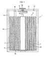
- FIG. 1 shows a sectional view of a rechargeable battery according to an embodiment of the present invention.
- FIG. 1 An exemplary embodiment of a non-aqueous lithium rechargeable battery 1 structure is illustrated in FIG. 1 .
- a positive electrode 2 and a negative electrode 4 are formed by materials which allow for extraction/insertion of lithium, a separator 6 is interposed between the positive electrode 2 and negative electrode 4, and an electrode assembly 8 is formed by winding and put it in a case 10.
- the top of the battery is sealed by a cap plate 12 and a gasket 14.
- a safety valve and an electrolyte injection hole 16 can be formed on the cap plate 12 to prevent an overpressure of a battery.
- an electrolyte 26 is injected into an electrolyte injection hole 16. Injected electrolyte 26 is impregnated into separator 6 and electrolyte injection hole 16 is sealed by a sealing agent.
- a plurality of batteries are fabricated by using the following well known methods in general.
- 94g of a lithium cobalt oxide (LiCoO 2 ), 3g of a carbon black and 3g of a polyvinylidene fluoride (PVDF) are dissolved and dispersed in 80g of N-Methylpyrrolidone, then the mixture becomes a cathode active material slurry.
- the cathode active material slurry is spread on the top of an aluminum foil, a current collector using a spreading device, and is dried, then a positive electrode is manufactured by pressing it with a roll press.
- MCMB® mesocarbon micro bead
- polyvinylidene fluoride a mesocarbon micro bead (Osaka Gas) and 10g of polyvinylidene fluoride are dissolved and dispersed in 80g of N-Methylpyrrolidone, and the mixture becomes an anode active material slurry.
- the anode active material slurry is spread on the top of a copper foil, current collector using a spreading device, and is dried, then a negative electrode is manufactured by pressing it with a roll press.
- the electrode is a solvent of 1.15M concentration having LiPF 6 dissolved by lithium salts in a solvent which has a ratio of ethylene carbonate: propylene carbonate: dimethyl carbonate of 3: 4: 1.
- Electrode assembly 8 wherein separator 6 is interposed between positive electrode 2 and negative electrode 4 and wound, is mounted in the inner of case 10, then electrolyte is injected into the case and electrolyte injection hole is sealed, thereby lithium-ion battery is fabricated.
- Separator 6 is characterized in which the maximum thermal shrinkages of vertical direction (TD) and horizontal direction (MD) are 0 to 30%.
- the ratio of maximum thermal shrinkage of the horizontal direction against the maximum thermal shrinkage of the vertical direction may be 0.8 to 1.3.
- Separator 6 of the present invention has the maximum thermal shrinkage of vertical direction and horizontal direction within a predetermined range - equal to or less than 30%.
- the lithium battery employing the separator whose ratio of maximum thermal shrinkage of horizontal direction against vertical direction is 0.8 to 1.3 represents an improved thermal stability.
- the maximum thermal shrinkage in the present invention denotes the value which the maximum contracted length of separator is divided by the original length of a specimen.
- TMA ThermoMechanical Analyzer
- a rectangular specimen was employed to measure the separator shrinkage.
- the rectangular specimen was a polyethylene sheet of thickness 16 ⁇ m, width 10mm, length 30mm, and was fixed to the jig of TMA in the length direction of the specimen.
- the gap between the jigs was set 10mm and 100gf force was applied to pull both ends of the specimen in two opposite directions.
- a tester After placing the specimen fixed to the jig into a temperature chamber, a tester measured the contracted length by increasing the temperature of the temperature chamber from room temperature to 160°C by a rate of 0°C per minute. The results were obtained by measuring the length change of the specimen according to the change of temperature, and calculating the shrinkage by dividing the contracted length by the length of the original specimen.
- Batteries are fabricated using various kinds of separator having different thermal shrinkage, and thermal stability tests of the batteries are done in an oven.
- the procedure of the thermal stability test is charging the battery 100% and putting it into the oven, then increasing temperature from room temperature to 150°C with a rate of 5°C per minute, and lastly measuring the time required for the battery to fire or explode by maintaining temperature at 150°C. The more the time required for the battery to fire or explode, the more excellent the thermal stability of the battery is.
- Table 1 and 2 show thermal shrinkage characteristics of various kinds of separators according to the embodiments of the present invention and comparative embodiments, and the results of thermal stability tests of lithium rechargeable battery employing corresponding separators.
- the vertical direction means axial direction of a jelly roll type electrode assembly of a battery
- the horizontal direction means the rotational direction of the jelly roll type electrode assembly.
- Separators A and D shown in Table 1 have thermal shrinkage characteristics as provided by the present invention, and separators E,F,G and H have thermal shrinkage characteristics that are out of the requested range of the present invention.
- Table 1 Thermal shrinkage characteristics of Separator Thermal stability of Battery Separator Maximum thermal shrinkage (%) Maximum thermal shrinkage rate (MD/TD) Time required for fire and explosion(av erage/minimum) (min.) Thermal stability evaluation Vertical direction(TD) Horizontal direction(MD) A 26 22 0.85 14.9/13.G Good D 6 5 0.83 15.7/14.1 Good
- the maximum thermal shrinkage of all separators A and D in table 1 is equal to or below 30%. And ratio of maximum thermal shrinkage of the horizontal direction against the maximum thermal shrinkage of the vertical direction is 0.8 to 1.3 based on 2 significant digits. All the results represents excellent thermal stability under 150°C oven tests.
- the maximum thermal shrinkage of separators E,F,G and H in table 2 is over 30%, or ratio of maximum thermal shrinkage of the horizontal direction against the maximum thermal shrinkage of the vertical direction is out of the range 0.8 to 1.3.
- the results are inferior under 150°C oven tests compared comparing to the results in Table 1.
- separator E For separator E, the average time required for a fire or an explosion is good, however the thermal stability is not excellent because the minimum time is short comparing to the results in Table 1.
- the maximum thermal shrinkage of separator E is very high with 31% in the vertical direction and 27% in the horizontal direction, it still shows a relatively high thermal stability because the ratio of thermal shrinkage is 0.9 which is within the requested range of the present invention. Therefore, the ratio of the thermal shrinkage is more important than the shrinkage along a single direction regarding the effect on thermal stability.
- the separators having the ratio of the maximum thermal shrinkage of horizontal direction against vertical direction ranging 0.8 to 1.1 tend to have better thermal characteristics than the separators having the ratio range of 1.1 to 1.3.
- a key to identify the thermal stability of separator is not a material of the separator itself, but the thermal shrinkage and the melting point.
- the present invention especially relates to the thermal shrinkage.
- polyolefins for example polypropylene fine porosity sheet which has similar characteristics with polyethylene sheet used in the exemplary tests, is used, a similar effect can be realized.
- thermal stability of battery can be raised by defining the maximum shrinkage ratio of the horizontal direction against the vertical direction, and the maximum shrinkage of both vertical direction and horizontal direction of the separator.
- lithium-ion batteries with an improved thermal stability than the conventional lithium batteries can be obtained by employing separator having the maximum thermal shrinkage at a predetermined range, without any particular limitation in other characteristics of the separator.
Landscapes
- Chemical & Material Sciences (AREA)
- Chemical Kinetics & Catalysis (AREA)
- Electrochemistry (AREA)
- General Chemical & Material Sciences (AREA)
- Engineering & Computer Science (AREA)
- Manufacturing & Machinery (AREA)
- Inorganic Chemistry (AREA)
- Materials Engineering (AREA)
- Secondary Cells (AREA)
- Cell Separators (AREA)
- Cell Electrode Carriers And Collectors (AREA)
- Battery Electrode And Active Subsutance (AREA)
Claims (7)
- Separator für wiederaufladbare Lithiumbatterie, wobei die maximale thermische Schrumpfung in vertikaler Richtung (TD) und in horizontaler Richtung (MD) 0 bis 30% beträgt und das Verhältnis von maximaler thermischer Schrumpfung in horizontaler Richtung zu maximaler thermischer Schrumpfung in vertikaler Richtung 0,8 bis 1,1 beträgt.
- Separator für wiederaufladbare Lithiumbatterie nach Anspruch 1, wobei der Separator aus einer porösen Folie aus Polyethylen oder Polypropylen besteht.
- Wiederaufladbare Lithiumbatterie, umfassend:eine Elektrodenbaugruppe mit einer positiven Elektrode, einer negativen Elektrode und einem Separator, der zwischen die positive Elektrode und die negative Elektrode eingeschoben ist;einen Elektrolyt;ein Behältnis, das die Elektrodenbaugruppe und den Elektrolyt aufnimmt; undeinen Separator nach Anspruch 1 oder 2.
- Wiederaufladbare Lithiumbatterie nach Anspruch 3, wobei zu der positiven Elektrode eine Aluminium-Baugruppe und eine Schicht aus aktivem Material für die positive Elektrode gehört und die Schicht aus aktivem Material für die positive Elektrode Lithiumcobaltoxid, Ruß und Polyvinylidenfluorid umfasst.
- Wiederaufladbare Lithiumbatterie nach Anspruch 3 oder 4, wobei zu der negativen Elektrode eine Kupferbaugruppe und eine Schicht aus aktivem Material für die negative Elektrode gehört und die Schicht aus aktivem Material für die negative Elektrode Mesocarbon-Microbeads (MCMB) und Polyvinylidenfluorid umfasst.
- Wiederaufladbare Lithiumbatterie nach Anspruch 3, 4 oder 5, wobei der Elektrolyt ein Lösungsmittel mit einer 1,15 M-Konzentration an LiPF6 ist, gelöst durch Lithiumsalze in einem Lösungsmittel, das ein Verhältnis von Ethylencarbonat/Propylencarbonat/Dimethylcarbonat von 3:4:1 aufweist.
- Wiederaufladbare Lithiumbatterie nach einem der Ansprüche 3 bis 6, wobei die Elektrodenbaugruppe eine Baugruppe von der Art einer Biskuitrolle umfasst, wobei die positive Elektrode, die negative Elektrode und der Separator gestapelt und gewickelt sind.
Applications Claiming Priority (1)
| Application Number | Priority Date | Filing Date | Title |
|---|---|---|---|
| KR1020060120207A KR100898670B1 (ko) | 2006-11-30 | 2006-11-30 | 리튬 이차 전지용 세퍼레이터 및 이를 채용한 리튬 이차전지 |
Publications (2)
| Publication Number | Publication Date |
|---|---|
| EP1928043A1 EP1928043A1 (de) | 2008-06-04 |
| EP1928043B1 true EP1928043B1 (de) | 2010-04-28 |
Family
ID=39185735
Family Applications (1)
| Application Number | Title | Priority Date | Filing Date |
|---|---|---|---|
| EP07121766A Active EP1928043B1 (de) | 2006-11-30 | 2007-11-28 | Wiederaufladbare Lithiumbatterie und Separator dafür |
Country Status (6)
| Country | Link |
|---|---|
| US (1) | US20080153004A1 (de) |
| EP (1) | EP1928043B1 (de) |
| JP (1) | JP5352075B2 (de) |
| KR (1) | KR100898670B1 (de) |
| CN (1) | CN101202335A (de) |
| DE (1) | DE602007006135D1 (de) |
Families Citing this family (4)
| Publication number | Priority date | Publication date | Assignee | Title |
|---|---|---|---|---|
| JPWO2015002094A1 (ja) * | 2013-07-05 | 2017-02-23 | Necエナジーデバイス株式会社 | 電池セル |
| JP6020929B2 (ja) * | 2013-09-09 | 2016-11-02 | トヨタ自動車株式会社 | 非水電解液二次電池 |
| CN109613049B (zh) * | 2018-10-20 | 2024-06-18 | 武汉惠强新能源材料科技有限公司 | 锂电池隔膜材料热收缩性能测试装置 |
| KR102440243B1 (ko) | 2019-02-21 | 2022-09-06 | 주식회사 엘지에너지솔루션 | 전극조립체 |
Family Cites Families (20)
| Publication number | Priority date | Publication date | Assignee | Title |
|---|---|---|---|---|
| US4957833A (en) * | 1988-12-23 | 1990-09-18 | Bridgestone Corporation | Non-aqueous liquid electrolyte cell |
| CN1134491C (zh) | 1999-02-19 | 2004-01-14 | 东燃化学株式会社 | 聚烯烃微多孔膜及其制造方法 |
| JP3471244B2 (ja) * | 1999-03-15 | 2003-12-02 | 株式会社東芝 | 非水電解液二次電池の製造方法 |
| JP2000348706A (ja) * | 1999-03-31 | 2000-12-15 | Mitsubishi Chemicals Corp | 電池用セパレーター |
| JP4659187B2 (ja) * | 1999-09-14 | 2011-03-30 | 日本バイリーン株式会社 | 電池用セパレータ |
| JP4427853B2 (ja) * | 1999-12-20 | 2010-03-10 | 三菱化学株式会社 | 二次電池 |
| US6686095B2 (en) * | 1999-12-28 | 2004-02-03 | Kabushiki Kaisha Toshiba | Gel electrolyte precursor and chemical battery |
| WO2001093350A1 (en) * | 2000-05-29 | 2001-12-06 | Mitsubishi Paper Mills Limited | Separator for electrochemical device and method for producing the same, and electrochemical device |
| JP4794099B2 (ja) * | 2001-09-28 | 2011-10-12 | 東レ東燃機能膜合同会社 | ポリオレフィン微多孔膜の製造方法 |
| KR100477744B1 (ko) * | 2001-10-31 | 2005-03-18 | 삼성에스디아이 주식회사 | 유기 전해액 및 이를 채용한 리튬 2차전지 |
| CN100559632C (zh) * | 2002-01-24 | 2009-11-11 | 日立麦克赛尔株式会社 | 内部装有非水二次电池的电子器械 |
| KR100560208B1 (ko) * | 2002-03-12 | 2006-03-10 | 에스케이씨 주식회사 | 상온에서 겔화가능한 겔 고분자 전해질용 조성물 |
| JP2004095383A (ja) * | 2002-08-30 | 2004-03-25 | Toshiba Corp | 非水電解質二次電池 |
| JP4381054B2 (ja) * | 2002-11-13 | 2009-12-09 | 日東電工株式会社 | 電池用セパレータのための部分架橋接着剤担持多孔質フィルムとその利用 |
| JP4612321B2 (ja) * | 2003-04-04 | 2011-01-12 | 株式会社東芝 | 非水電解質二次電池 |
| US7790272B2 (en) * | 2003-06-04 | 2010-09-07 | Toray Industries, Inc. | Multilayer film and biaxially oriented polyester film |
| JP4662533B2 (ja) | 2003-08-26 | 2011-03-30 | 日東電工株式会社 | 電池用セパレータのための反応性ポリマー担持多孔質フィルムとそれを用いる電池の製造方法 |
| JP4705334B2 (ja) * | 2004-03-19 | 2011-06-22 | 株式会社巴川製紙所 | 電子部品用セパレータ及びその製造方法 |
| JP2005343958A (ja) * | 2004-06-01 | 2005-12-15 | Tonen Chem Corp | ポリエチレン微多孔膜の製造方法並びにその微多孔膜及び用途 |
| KR100635736B1 (ko) * | 2005-03-08 | 2006-10-17 | 삼성에스디아이 주식회사 | 음극 활물질 및 이를 포함하는 리튬 이차 전지 |
-
2006
- 2006-11-30 KR KR1020060120207A patent/KR100898670B1/ko active Active
-
2007
- 2007-11-05 JP JP2007287672A patent/JP5352075B2/ja active Active
- 2007-11-28 EP EP07121766A patent/EP1928043B1/de active Active
- 2007-11-28 DE DE602007006135T patent/DE602007006135D1/de active Active
- 2007-11-29 US US11/987,383 patent/US20080153004A1/en not_active Abandoned
- 2007-11-30 CN CNA200710195854XA patent/CN101202335A/zh active Pending
Also Published As
| Publication number | Publication date |
|---|---|
| JP2008140775A (ja) | 2008-06-19 |
| KR100898670B1 (ko) | 2009-05-22 |
| KR20080049545A (ko) | 2008-06-04 |
| EP1928043A1 (de) | 2008-06-04 |
| CN101202335A (zh) | 2008-06-18 |
| DE602007006135D1 (de) | 2010-06-10 |
| JP5352075B2 (ja) | 2013-11-27 |
| US20080153004A1 (en) | 2008-06-26 |
Similar Documents
| Publication | Publication Date | Title |
|---|---|---|
| US10622611B2 (en) | Separator for nonaqueous electrolyte battery, and nonaqueous electrolyte battery | |
| KR100687159B1 (ko) | 고체 전해질 전지 | |
| US7311994B2 (en) | Separator for lithium ion secondary battery and lithium ion secondary battery provided therewith | |
| US9991489B2 (en) | Porous layer, laminated body, nonaqueous electrolyte secondary battery member including the porous layer, and nonaqueous electrolyte secondary battery including the porous layer | |
| KR101136254B1 (ko) | 이차전지 | |
| US7931983B2 (en) | Lithium ion secondary battery | |
| EP2696393B1 (de) | Separator für nichtwässrige sekundärbatterien und nichtwässrige sekundärbatterie | |
| US9882189B2 (en) | Separator for nonaqueous electrolyte battery, and nonaqueous electrolyte battery | |
| US7252689B2 (en) | Method for fabricating lithium ion secondary battery | |
| KR20180077190A (ko) | 비수계 이차전지용 세퍼레이터 및 비수계 이차전지 | |
| EP1063720B1 (de) | Batterie mit nichtwässrigen Elektrolyten | |
| US8231999B2 (en) | Separator and battery using the same | |
| US8129045B2 (en) | Electrochemical element | |
| JP4629998B2 (ja) | 密閉型二次電池 | |
| EP1928043B1 (de) | Wiederaufladbare Lithiumbatterie und Separator dafür | |
| EP1562251B1 (de) | Organische Elektrolytlösung und Lithiumbatterie diese Lösung enthaltend | |
| KR102712792B1 (ko) | 세퍼레이터 및 이를 포함하는 전기화학소자 | |
| Yamamoto et al. | 4.4 V lithium-ion polymer batteries with a chemical stable gel electrolyte | |
| JP2006261059A (ja) | 非水電解質二次電池 | |
| KR101178710B1 (ko) | 이차 전지 | |
| JP2009249488A (ja) | 複合多孔質フィルムおよびそれを用いた電池用セパレータ、並びに非水系電解液二次電池 | |
| US20260112709A1 (en) | Separator, preparation method thereof and electrochemical device including the same | |
| JP2002343429A (ja) | 非水電解質二次電池 |
Legal Events
| Date | Code | Title | Description |
|---|---|---|---|
| PUAI | Public reference made under article 153(3) epc to a published international application that has entered the european phase |
Free format text: ORIGINAL CODE: 0009012 |
|
| 17P | Request for examination filed |
Effective date: 20071128 |
|
| AK | Designated contracting states |
Kind code of ref document: A1 Designated state(s): AT BE BG CH CY CZ DE DK EE ES FI FR GB GR HU IE IS IT LI LT LU LV MC MT NL PL PT RO SE SI SK TR |
|
| AX | Request for extension of the european patent |
Extension state: AL BA HR MK RS |
|
| AKX | Designation fees paid |
Designated state(s): DE FR GB HU |
|
| RAP1 | Party data changed (applicant data changed or rights of an application transferred) |
Owner name: SAMSUNG SDI CO., LTD. |
|
| GRAP | Despatch of communication of intention to grant a patent |
Free format text: ORIGINAL CODE: EPIDOSNIGR1 |
|
| GRAS | Grant fee paid |
Free format text: ORIGINAL CODE: EPIDOSNIGR3 |
|
| GRAA | (expected) grant |
Free format text: ORIGINAL CODE: 0009210 |
|
| AK | Designated contracting states |
Kind code of ref document: B1 Designated state(s): DE FR GB HU |
|
| REG | Reference to a national code |
Ref country code: GB Ref legal event code: FG4D |
|
| REF | Corresponds to: |
Ref document number: 602007006135 Country of ref document: DE Date of ref document: 20100610 Kind code of ref document: P |
|
| PLBE | No opposition filed within time limit |
Free format text: ORIGINAL CODE: 0009261 |
|
| STAA | Information on the status of an ep patent application or granted ep patent |
Free format text: STATUS: NO OPPOSITION FILED WITHIN TIME LIMIT |
|
| 26N | No opposition filed |
Effective date: 20110131 |
|
| PG25 | Lapsed in a contracting state [announced via postgrant information from national office to epo] |
Ref country code: HU Free format text: LAPSE BECAUSE OF FAILURE TO SUBMIT A TRANSLATION OF THE DESCRIPTION OR TO PAY THE FEE WITHIN THE PRESCRIBED TIME-LIMIT Effective date: 20101029 |
|
| REG | Reference to a national code |
Ref country code: FR Ref legal event code: PLFP Year of fee payment: 9 |
|
| REG | Reference to a national code |
Ref country code: FR Ref legal event code: PLFP Year of fee payment: 10 |
|
| REG | Reference to a national code |
Ref country code: FR Ref legal event code: PLFP Year of fee payment: 11 |
|
| REG | Reference to a national code |
Ref country code: FR Ref legal event code: PLFP Year of fee payment: 12 |
|
| REG | Reference to a national code |
Ref country code: DE Ref legal event code: R079 Ref document number: 602007006135 Country of ref document: DE Free format text: PREVIOUS MAIN CLASS: H01M0002160000 Ipc: H01M0050409000 |
|
| P01 | Opt-out of the competence of the unified patent court (upc) registered |
Effective date: 20230528 |
|
| PGFP | Annual fee paid to national office [announced via postgrant information from national office to epo] |
Ref country code: DE Payment date: 20251104 Year of fee payment: 19 |
|
| PGFP | Annual fee paid to national office [announced via postgrant information from national office to epo] |
Ref country code: GB Payment date: 20251030 Year of fee payment: 19 |
|
| PGFP | Annual fee paid to national office [announced via postgrant information from national office to epo] |
Ref country code: FR Payment date: 20251117 Year of fee payment: 19 |