EP1928113A1 - Dispositif et procede de transmission radio - Google Patents
Dispositif et procede de transmission radio Download PDFInfo
- Publication number
- EP1928113A1 EP1928113A1 EP06832454A EP06832454A EP1928113A1 EP 1928113 A1 EP1928113 A1 EP 1928113A1 EP 06832454 A EP06832454 A EP 06832454A EP 06832454 A EP06832454 A EP 06832454A EP 1928113 A1 EP1928113 A1 EP 1928113A1
- Authority
- EP
- European Patent Office
- Prior art keywords
- section
- low
- rate
- control information
- low rate
- Prior art date
- Legal status (The legal status is an assumption and is not a legal conclusion. Google has not performed a legal analysis and makes no representation as to the accuracy of the status listed.)
- Withdrawn
Links
Images


Classifications
-
- H—ELECTRICITY
- H04—ELECTRIC COMMUNICATION TECHNIQUE
- H04L—TRANSMISSION OF DIGITAL INFORMATION, e.g. TELEGRAPHIC COMMUNICATION
- H04L5/00—Arrangements affording multiple use of the transmission path
- H04L5/003—Arrangements for allocating sub-channels of the transmission path
- H04L5/0037—Inter-user or inter-terminal allocation
-
- H—ELECTRICITY
- H04—ELECTRIC COMMUNICATION TECHNIQUE
- H04L—TRANSMISSION OF DIGITAL INFORMATION, e.g. TELEGRAPHIC COMMUNICATION
- H04L1/00—Arrangements for detecting or preventing errors in the information received
- H04L1/0001—Systems modifying transmission characteristics according to link quality, e.g. power backoff
- H04L1/0002—Systems modifying transmission characteristics according to link quality, e.g. power backoff by adapting the transmission rate
- H04L1/0003—Systems modifying transmission characteristics according to link quality, e.g. power backoff by adapting the transmission rate by switching between different modulation schemes
-
- H—ELECTRICITY
- H04—ELECTRIC COMMUNICATION TECHNIQUE
- H04L—TRANSMISSION OF DIGITAL INFORMATION, e.g. TELEGRAPHIC COMMUNICATION
- H04L1/00—Arrangements for detecting or preventing errors in the information received
- H04L1/0001—Systems modifying transmission characteristics according to link quality, e.g. power backoff
- H04L1/0009—Systems modifying transmission characteristics according to link quality, e.g. power backoff by adapting the channel coding
- H04L1/0013—Rate matching, e.g. puncturing or repetition of code symbols
-
- H—ELECTRICITY
- H04—ELECTRIC COMMUNICATION TECHNIQUE
- H04L—TRANSMISSION OF DIGITAL INFORMATION, e.g. TELEGRAPHIC COMMUNICATION
- H04L27/00—Modulated-carrier systems
- H04L27/26—Systems using multi-frequency codes
- H04L27/2601—Multicarrier modulation systems
- H04L27/2602—Signal structure
-
- H—ELECTRICITY
- H04—ELECTRIC COMMUNICATION TECHNIQUE
- H04L—TRANSMISSION OF DIGITAL INFORMATION, e.g. TELEGRAPHIC COMMUNICATION
- H04L5/00—Arrangements affording multiple use of the transmission path
- H04L5/003—Arrangements for allocating sub-channels of the transmission path
- H04L5/0044—Allocation of payload; Allocation of data channels, e.g. PDSCH or PUSCH
- H04L5/0046—Determination of the number of bits transmitted on different sub-channels
-
- H—ELECTRICITY
- H04—ELECTRIC COMMUNICATION TECHNIQUE
- H04L—TRANSMISSION OF DIGITAL INFORMATION, e.g. TELEGRAPHIC COMMUNICATION
- H04L5/00—Arrangements affording multiple use of the transmission path
- H04L5/0091—Signalling for the administration of the divided path, e.g. signalling of configuration information
- H04L5/0094—Indication of how sub-channels of the path are allocated
-
- H—ELECTRICITY
- H04—ELECTRIC COMMUNICATION TECHNIQUE
- H04L—TRANSMISSION OF DIGITAL INFORMATION, e.g. TELEGRAPHIC COMMUNICATION
- H04L1/00—Arrangements for detecting or preventing errors in the information received
- H04L1/0001—Systems modifying transmission characteristics according to link quality, e.g. power backoff
- H04L1/0002—Systems modifying transmission characteristics according to link quality, e.g. power backoff by adapting the transmission rate
- H04L1/0003—Systems modifying transmission characteristics according to link quality, e.g. power backoff by adapting the transmission rate by switching between different modulation schemes
- H04L1/0004—Systems modifying transmission characteristics according to link quality, e.g. power backoff by adapting the transmission rate by switching between different modulation schemes applied to control information
-
- H—ELECTRICITY
- H04—ELECTRIC COMMUNICATION TECHNIQUE
- H04L—TRANSMISSION OF DIGITAL INFORMATION, e.g. TELEGRAPHIC COMMUNICATION
- H04L1/00—Arrangements for detecting or preventing errors in the information received
- H04L1/0001—Systems modifying transmission characteristics according to link quality, e.g. power backoff
- H04L1/0009—Systems modifying transmission characteristics according to link quality, e.g. power backoff by adapting the channel coding
- H04L1/001—Systems modifying transmission characteristics according to link quality, e.g. power backoff by adapting the channel coding applied to control information
-
- H—ELECTRICITY
- H04—ELECTRIC COMMUNICATION TECHNIQUE
- H04L—TRANSMISSION OF DIGITAL INFORMATION, e.g. TELEGRAPHIC COMMUNICATION
- H04L1/00—Arrangements for detecting or preventing errors in the information received
- H04L1/0001—Systems modifying transmission characteristics according to link quality, e.g. power backoff
- H04L1/0023—Systems modifying transmission characteristics according to link quality, e.g. power backoff characterised by the signalling
- H04L1/0026—Transmission of channel quality indication
-
- H—ELECTRICITY
- H04—ELECTRIC COMMUNICATION TECHNIQUE
- H04L—TRANSMISSION OF DIGITAL INFORMATION, e.g. TELEGRAPHIC COMMUNICATION
- H04L5/00—Arrangements affording multiple use of the transmission path
- H04L5/0001—Arrangements for dividing the transmission path
- H04L5/0003—Two-dimensional division
- H04L5/0005—Time-frequency
- H04L5/0007—Time-frequency the frequencies being orthogonal, e.g. OFDM(A) or DMT
-
- H—ELECTRICITY
- H04—ELECTRIC COMMUNICATION TECHNIQUE
- H04W—WIRELESS COMMUNICATION NETWORKS
- H04W72/00—Local resource management
- H04W72/12—Wireless traffic scheduling
- H04W72/121—Wireless traffic scheduling for groups of terminals or users
-
- Y—GENERAL TAGGING OF NEW TECHNOLOGICAL DEVELOPMENTS; GENERAL TAGGING OF CROSS-SECTIONAL TECHNOLOGIES SPANNING OVER SEVERAL SECTIONS OF THE IPC; TECHNICAL SUBJECTS COVERED BY FORMER USPC CROSS-REFERENCE ART COLLECTIONS [XRACs] AND DIGESTS
- Y02—TECHNOLOGIES OR APPLICATIONS FOR MITIGATION OR ADAPTATION AGAINST CLIMATE CHANGE
- Y02D—CLIMATE CHANGE MITIGATION TECHNOLOGIES IN INFORMATION AND COMMUNICATION TECHNOLOGIES [ICT], I.E. INFORMATION AND COMMUNICATION TECHNOLOGIES AIMING AT THE REDUCTION OF THEIR OWN ENERGY USE
- Y02D30/00—Reducing energy consumption in communication networks
- Y02D30/50—Reducing energy consumption in communication networks in wire-line communication networks, e.g. low power modes or reduced link rate
Definitions
- the present invention relates to a radio transmitting apparatus and radio transmission method in an OFDM (Orthogonal Frequency Division Multiplexing) system.
- OFDM Orthogonal Frequency Division Multiplexing
- OFDM refers to a multicarrier transmission technique for transmitting data in parallel using a large number of subcarriers, and is known as a technique that has high frequency utilization efficiency and characteristics of reducing inter-symbol interference under a multipath environment and that is effective in improving transmission efficiency.
- Non-Patent Document 1 A technique is studied of performing frequency scheduling when this OFDM is used in downlink and data for a plurality of mobile stations is frequency-multiplexed on a plurality of subcarriers (for example, see Non-Patent Document 1).
- a base station allocates subcarriers to mobile stations adaptively based on received quality of each frequency band at the mobile stations, so that it is possible to obtain a maximal multi-user diversity effect and perform communication very efficiently.
- Non-Patent Document 1 R1-050590, "Physical Channels and Multiplexing in Evolved UTRA Downlink", NTT DoCoMo, 3GPP TSG-RAN WG1, 2005/06
- the radio transmitting apparatus of the present invention includes an allocating section that performs frequency scheduling for a mobile station apparatus and allocates a resource block comprising a control unit in frequency scheduling, to the mobile station apparatus; a grouping section that groups a plurality of mobile station apparatuses that satisfy a predetermined requirement as low rate user equipment that receives low rate data, and assigns a group identity to the grouped low rate user equipment; a shared control channel generating section that generates a shared control channel including the group identity; a control information generating section that generates control information showing allocation information of a resource block allocated to the low rate user equipment; a multiplexing section that multiplexes the shared control channel, data and the control information, and multiplexes the control information on a data field of the resource block to which the low rate data is allocated; and a transmitting section that transmits a multiplexed signal.
- the radio transmission method of the present invention includes an allocating step of performing frequency scheduling for a mobile station apparatus and allocating a resource block comprising a control unit of frequency scheduling, to the mobile station apparatus; a grouping step of grouping a plurality of mobile station apparatuses that satisfy a predetermined requirement as low rate user equipment that receives low rate data, and assigning a group identity to the grouped low rate user equipment; and a multiplexing step of multiplexing a shared control channel including the group identity, control information showing allocation information of a resource block allocated to the low rate user equipment and data, and multiplexing the control information on a data field of the resource block to which the low rate data is allocated.
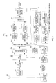
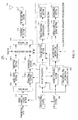
- FIG.1 is a block diagram showing the configuration of transmitting apparatus 100 according to Embodiment 1 of the present invention.
- error correction coding section 101 performs error correction coding on transmission data at a coding rate outputted from MCS setting section 107 described later, and outputs the result to S/P (serial/parallel) section 102.
- S/P section 102 converts serial encoded data outputted from error correction coding section 101 into a plurality of sequences of parallel encoded data according to a data size that can be transmitted per RB, and outputs the sequences of encoded data to modulating sections 103-1 to 103-n, respectively.
- Modulating sections 103-1 to 103-n modulate the encoded data outputted from S/P section 102 per RB according to the modulation scheme outputted from MCS setting section 107, generates data symbols, and outputs the generated data symbols to corresponding repetition sections 104-1 to 104-n.
- Repetition sections 104-1 to 104-n perform symbol repetition on the data symbols outputted from modulating sections 103-1 to 103-n per RB according to the number of repetitions outputted from MCS setting section 107 and output the results to multiplexing section 117.
- CQI extracting section 105 acquires feedback information transmitted from receiving apparatus 200 described later and extracts CQI information from the acquired feedback information.
- the extracted CQI information is outputted to RB allocating section 106 and MCS setting section 107.
- RB allocating section 106 allocates mobile stations (hereinafter "UE") to RB's using an arbitrary scheduling method (for example, max CIR method, proportional fairness method), based on the CQI information outputted from CQI extracting section 105.
- RB allocating section 106 outputs the ID's of UE's allocated to RB's (allocated UE-ID's) and allocation RB numbers to MCS setting section 107 and group ID assigning section 108.
- MCS setting section 107 determines per UE maximum MCS parameters (the coding rate of an error correction code, the modulation scheme and the number of repetitions) that make the received packet error rate less than 0.1, based on the allocated UE-ID's and allocation RB numbers outputted from RB allocating section 106, and the CQI information outputted from CQI extracting section 105.
- the determined coding rate is outputted to error correction coding section 101
- the modulation scheme is outputted to modulating sections 103-1 to 103-n
- the number of repetitions is outputted to repetition sections 104-1 to 104-n.
- the determined MCS parameters are outputted to group ID assigning section 108 and SCCH processing section 109.
- Group ID assigning section 108 determines whether each UE receives low-rate data (hereinafter “low-rate UE”) or receives high-rate data (hereinafter “high-rate UE”) based on, for example, the determination criterion as shown in FIG.2 , using the allocated UE-ID's and allocation RB numbers outputted from RB allocating section 106, and the MCS parameters outputted from MCS setting section 107.
- low-rate UE low-rate data
- high-rate UE receives high-rate data
- the UE when the modulation level shown in the MCS parameters is QPSK or lower and the amount of allocated resource is 1 RB or less, the UE is determined to be a low-rate UE, and is determined to be a high-rate UE otherwise.
- Group ID assigning section 108 groups a plurality of UE's determined as low-rate UE's and assigns a group ID to the grouped UE's.
- the allocated UE-ID's of the grouped UE's hereinafter "low-rate UE-ID" are changed to the assigned group ID.
- the assigned group ID, low-rate UE-ID's and allocation RB numbers are outputted, and, for high-rate UE's, the allocated UE-ID's and allocation RB numbers are outputted to SCCH processing section 109. Further, the low-rate UE-ID's and allocation RB numbers are outputted to low-rate control information processing section 113.
- SCCH processing section 109 has SCCH generating section 110, error correction coding section 111 and modulating section 112.
- SCCH generating section 110 integrates the MCS parameters outputted from MCS setting section 107, low-rate UE-ID's and allocation RB numbers outputted from group ID assigning section 108, generates SCCH information, and outputs the generated SCCH information to error correction coding section 111.
- Error correction coding section 111 performs error correction coding on the SCCH information, and modulating section 112 modulates encoded data of the SCCH information and outputs the result to multiplexing section 117.
- the coding rate at error correction coding section 111 and the modulation scheme at modulating section 112 are determined in advance and not limited to specific coding rates and specific modulation schemes.
- Low-rate control information processing section 113 has low-rate control information generating section 114, error correction coding section 115 and modulating section 116.
- Low-rate control information generating section 114 integrates the low-rate UE-ID's and allocation RB numbers outputted from group ID assigning section 108, generates low-rate control information and outputs the information to error correction coding section 115.
- Error correction coding section 115 performs error correction coding on the low-rate control information, and modulating section 116 modulates encoded data of the low-rate control information and outputs the result to multiplexing section 117.
- the coding rate at error correction coding section 115 and the modulation scheme at modulating section 116 are determined in advance.
- Multiplexing section 117 multiplexes a pilot channel, SCCHs outputted from SCCH processing section 109, low-rate control channel outputted from low-rate control information processing section 113, and data symbols outputted from repetition sections 104-1 to 104-n, and outputs the multiplexed signal to IFFT section 118.
- the low-rate control channel is multiplexed on the heads of data channel fields of the RB's to which low-rate UE's are allocated.
- IFFT section 118 converts the multiplexed signal outputted from multiplexing section 117 from a frequency domain signal to a time domain signal by performing IFFT (Inverse Fast Fourier Transform) processing, and generates an OFDM symbol which is a multicarrier signal.
- the generated OFDM symbol is outputted to GI adding section 119.
- GI adding section 119 adds the same signal as the tail part of the OFDM symbol outputted from IFFT section 118 to the head of the OFDM symbol as a GI (Guard Interval) and outputs the result to RF transmitting section 120.
- GI Guard Interval
- RF transmitting section 120 performs transmission processing such as D/A conversion, amplification and up-conversion on the OFDM symbol outputted from GI adding section 119, and transmits the signal subjected to transmission processing to receiving apparatus 200 via antenna 121.
- FIG. 3 is ablockdiagramshowingthe configuration of receiving apparatus 200 according to Embodiment 1 of the present invention.
- RF receiving section 202 receives the OFDM symbol transmitted from transmitting apparatus 100 shown in FIG.1 via antenna 201, performs reception processing such as down-conversion and A/D conversion on the received OFDM symbol and outputs the result to GI removing section 203.
- GI removing section 203 removes the GI added to the OFDM symbol and outputs the OFDM symbol to FFT section 204.
- FFT section 204 performs FFT (Fast Fourier Transform) processing on the OFDM symbol outputted from GI removing section 203, converts the symbol from a time domain signal to a frequency domain signal, and obtains the pilot signal and other received signals.
- the pilot signal is outputted to channel estimating section 205, and other received signals are outputted to equalizing section 206.
- Channel estimating section 205 performs channel estimation per subcarrier using the pilot signal for each subcarrier outputted from FFT section 204, and outputs a channel estimation value to equalizing section 206 and CQI generating section 220. Further, channel estimating section 205 detects the signal power value (S), interference power value (I) and noise power value (N) of the pilot signal for each subcarrier and outputs the SINR value to CQI generating section 220.
- S signal power value
- I interference power value
- N noise power value
- Equalizing section 206 performs equalizing processing on the received signal outputted from FFT section 204 using the channel estimation value outputted from channel estimating section 205.
- Demultiplexing section 207 demultiplexes the received signal outputted from equalizing section 206 into the received data, the SCCHs and the low-rate control channel, outputs received data to symbol combining sections 212-1 to 212-n per RB, outputs the SCCHs to SCCH receiving section 208 and outputs the low-rate control channel to low-rate control information receiving section 216.
- the low-rate control channel is demultiplexed from the received data according to the allocation RB number of the low-rate allocation control channel inputted from SCCH receiving section 208.
- SCCH receiving section 208 has symbol combining section 209, demodulating section 210 and error correction decoding section 211.
- Symbol combining section 209 performs symbol combining on the SCCHs outputted from demultiplexing section 207
- demodulating section 210 demodulates the SCCHs subjected to symbol combining
- error correction decoding section 211 decodes the demodulated SCCHs and acquires allocation RB numbers, timing slots and MCS parameters for the allocation RB's.
- SCCH receiving section 208 outputs the allocation RB number of the low-rate control channel included in the SCCH to demultiplexing section 207.
- Demodulation processing and error correction decoding processing are performed according to predetermined MCS parameters and support the coding rate at error correction coding section 111 and the modulation scheme at modulating section 112 of transmitting apparatus 100 shown in FIG.1 , respectively.
- Symbol combining sections 212-1 to 212-n perform symbol combining on symbols duplicated through repetition and a duplication source symbol out of received data outputted from demultiplexing section 207, according to an MCS parameter (the number of repetitions) outputted from SCCH receiving section 208, and output the results to corresponding demodulating sections 213-1 to 213-n.
- MCS parameter the number of repetitions
- Demodulating sections 213-1 to 213-n demodulate the combined symbols outputted from symbol combining sections 212-1 to 212-n according to an MCS parameter (modulation scheme) outputted from SCCH receiving section 208 and outputs the results to P/S section 214.
- MCS parameter modulation scheme
- P/S section 214 converts parallel data symbols outputted from demodulating sections 213-1 to 213-n into serial data symbols and outputs the results to error correction decoding section 215.
- Error correction decoding section 215 performs error correction decoding on the data symbols outputted from P/S section 214 according to MCS parameters (coding rates) outputted from SCCH receiving section 208. By this means, received data is obtained.
- Low-rate control information receiving section 216 has symbol combining section 217, demodulating section 218 and error correction decoding section 219.
- Symbol combining section 217 performs symbol combining on the low-rate control information outputted from demultiplexing section 207
- demodulating section 218 demodulates the low-rate control information subjected to symbol combining
- error correction decoding section 219 performs error correction decoding on the demodulated low-rate control information.
- CQI generating section 220 generates a CQI showing an SINR value of each RB outputted from channel estimating section 205.
- the generated CQI is encoded at error correction coding section 221, modulated at modulating section 222, subjected to transmission processing such as D/A conversion, amplification and up-conversion at RF transmitting section 223, and then transmitted to transmitting apparatus 100 shown in FIG.1 from antenna 201.
- FIG.4 shows arrangement of a signal in which physical channels (pilot channel, SCCHs, shared data channel and low-rate control channel) are multiplexed.
- the number of RB's is eight
- the number of low-rate UE's is four (UE-1 to UE-4)
- the number of high-rate UE's is three (UE-5 to UE-7)
- the number of MCS levels is four
- RB allocating section 106 allocates low-rate UE's (UE-1 to UE-4) to RB-1 and allocates high-rate UE's (UE-5 to UE-7) to RB-2 to RB-8
- a low-rate control channel is multiplexed on the head of a data channel field of RB-1 to which low-rate UE's are allocated as shown in FIG.4 .
- FIG.5 shows an SCCH format generated by SCCH processing section 109 shown in FIG.1
- FIG.6 shows allocation information in an SCCH.
- UE-8 shown in FIG.5 and FIG. 6 is obtained by replacing low-rate UE-ID's (UE-1 to UE-4) for four UE's with a group ID for a low-rate group by group ID assigning section 108. That is, the allocated UE-ID of UE's receiving low-rate data allocated to RB's by RB allocating section 106 is reported as a group ID using an SCCH.
- FIG.7 shows the format of a low-rate control channel for reference.
- TS's (Timing Slots) shown in FIG.7 show an allocation resource field of RB-1 in FIG.4 , and show that UE-1 is allocated to TS-1 and UE-2 is allocated to TS-2. Further, FIG.7 shows that UE-3 is allocated to TS-3 and UE-4 is allocated to TS-4.
- FIG.4 by arranging a low-rate control channel to an RB to which low-rate UE's are allocated, it is possible to eliminate the field for storing SCCHs for low-rate UE's from RB's to which high-rate UE's are allocated. This is shown in FIG.8 .
- the field shown by a dotted box can be improved as a field for allocating high-rate UE's.
- Embodiment 1 by grouping UE's receiving low-rate data, performing frequency allocation using a group ID, and arranging control information showing timing slots to which low-rate UE's are allocated, in RB's to which low-rate data is allocated, a data field of RB's for allocating high-rate data can be improved, so that it is possible to accommodate a large number of low-rate UE's and prevent a decrease in system throughput.
- allocation TS numbers and UE-TD's are not encoded per RB, but may be encoded collectively using the same coding rate. By this means, it is possible to obtain a higher coding gain and improve the error rate of low-rate control information.
- the receiving apparatus can perform reception processing using MCS parameters according to channel characteristics, so that it is possible to improve throughput of low-rate UE's.
- low-rate UE's when a plurality of low-rate UE's are each arranged in one RB, as shown in FIG.10 , it is also possible to group low-rate UE's, report RB's to which the low-rate UE group is allocated, using SCCHs, and report the MCSs and the like for each low-rate UE using low-rate control information.
- FIG.11 is a block diagram showing the configuration of transmitting apparatus 300 according to Embodiment 2 of the present invention.
- CQI extracting section 301 acquires feedback information transmitted from the receiving apparatus, extracts CQI information from the acquired feedback information, and outputs the extracted CQI information to RB allocating section 106, MCS setting section 107 and low-rate control information allocating section 303.
- This CQI information reports reception characteristics of each RB estimated at each UE using the SINR or MCS.
- Group ID assigning section 302 determines whether each UE receives low-rate data or high-rate data, using the allocated UE-ID's and allocation RB numbers outputted from RB allocating section 106 and the MCS parameters outputted from MCS setting section 107.
- Group ID assigning section 302 groups a plurality of UE's determined as low-rate UE's, and assigns a group ID to the grouped UE's. For low-rate UE's, the assigned group ID, the low-rate UE-ID's and allocation RB numbers are outputted, and, for high-rate UE's, the allocated UE-ID's and allocation RB numbers are outputted to SCCH processing section 109. Further, the low-rate UE-ID's and allocation RB numbers are outputted to low-rate control information processing section 113 and low-rate control information allocating section 303.
- Low-rate control information allocating section 303 acquires reception characteristics of each RB outputted from group ID assigning section 302 from the CQI information outputted from CQI extracting section 301, determines the RB which is reported as having good reception characteristics by the largest number of CQI information among the CQI information transmitted from the low-rate UE's, as the RB having the best reception characteristics, and allocates low-rate control information to this RB collectively.
- the allocation information (allocation RB number) of low-rate control information is outputted to SCCH processing section 109.
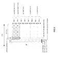
- FIG.12 shows arrangement of a signal in which physical channels (pilot channel, SCCHs, shared data channel and low-rate control channel) are multiplexed.
- the number of RB's is eight
- the number of low-rate UE's is eight (UE-1 to UE-8)
- the number of high-rate UE's is three (UE-9 to UE-11)
- the number of MCS levels is four.
- allocation RB numbers, allocated UE-ID's and MCSs are reported using SCCHs.
- FIG. 12 shows a case of allocating low-rate control information collectively to RB-1 with the best reception characteristics, allocating low-rate UE's (UE-1 to UE-8) to RB-1 and RB-2, which is adjacent to RB-1, and further allocating high-rate UE's (UE-9 to UE-11) to RB-3 to RB-8.
- low-rate control channels are multiplexed collectively at the head of a data channel field of RB-1 with the best reception characteristics.
- allocation is performed such that the UE-ID and the timing number become the same, but the present invention is not limited to this allocation.
- Embodiment 2 by arranging low-rate control information collectively to the RB with the best received quality, it is possible to improve the error rate of low-rate control information.
- the number of RB's to which the low-rate UE with the best received quality is allocated is one, if there are a plurality of such RB's, low-rate control information may be divided and arranged in these plurality of RB's.
- the configuration of the transmitting apparatus according to Embodiment 3 of the present invention is the same as the configuration of transmitting apparatus 100 according to Embodiment 1 except the part of functions, and so will be described using FIG.1 .
- group ID assigning section 108 groups low-rate UE's on condition that all low-rate UE's allocated to the same RB have the same MCS, and assigns a group ID to the grouped UE's.
- FIG.13 shows arrangement of a signal in which physical channels (pilot channel, SCCHs, shared data channel and low-rate control channel) are multiplexed.
- the number of RB's is eight
- the number of low-rate UE's is eight (UE-1 to UE-8)
- the number of high-rate UE's is three (UE-9 to UE-11)
- the number of MCS levels is four.
- allocation RB numbers, allocated UE-ID's and MCSs are reported using SCCHs.
- low-rate UE-1 to UE-8 having the same MCS are grouped, and this MCS is reported using an SCCH, so that it is possible to reduce an MCS for each low-rate UE from low-rate control information.
- allocation is performed such that the UE-ID and the timing number become the same, but the present invention is not limited to this allocation.
- Embodiment 3 by grouping low-rate UE's for which the same MCS is set and reporting this MCS using an SCCH, it is not necessary to include the MCS for each low-rate UE in low-rate control information, so that it is possible to reduce the amount of low-rate control information.
- the receiving apparatus reports the moving speed of the receiving apparatus together with the received signal level as a CQI to the transmitting apparatus.
- FIG.14 is a block diagram showing the configuration of transmitting apparatus 400 according to Embodiment 4 of the present invention.
- CQI extracting section 401 acquires information showing the moving speed of the receiving apparatus included in feedback information from the receiving apparatus and extracts CQI information and moving speed information from the feedback information.
- CQI extracting section 401 outputs the extracted CQI information to RB allocating section 106 and MCS setting section 107, and outputs the moving speed information to group ID assigning section 402.
- group ID assigning section 402 groups these low-rate UE's and assigns a group ID to the grouped UE's.
- the configuration of the transmitting apparatus according to Embodiment 5 of the present invention is the same as the configuration of transmitting apparatus 100 according to Embodiment 1 except the part of functions, and so will be described using FIG.1 .
- SCCH processing section 109 generates an SCCH including an allocation rule for low-rate UE's in each TTI included in a frame, in a TTI at the head of this frame.
- the allocation rule for low-rate UE's includes, for example, in each TTI, specifying low-rate UE's to be allocated in ascending order of the RB number out of RB's other than the RB's to which high-rate UE's are allocated.
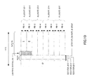
- FIG.15 shows arrangement of a signal in which physical channels (pilot channel, SCCHs, shared data channel and low-rate control channel) are multiplexed.
- the number of RB's is eight
- the number of low-rate UE's is four (UE-1 to UE-4)
- the number of high-rate UE's is three (UE-5 to UE-7)
- the number of MCS levels is four.
- allocation RB numbers, allocated UE-ID's and MCSs are reported using SCCHs.
- FIG.15 shows a state where, in TTI-#1, which is the head of a frame, an SCCH including the allocation rule for low-rate UE's is multiplexed.
- the allocation rule specifies to allocate low-rate UE-4, UE-1, UE-2 and UE-3 in ascending order of the RB number, out of RB's other than the RB to which high-rate UE's are allocated.
- RB-2,RB-3, RB-5 and RB-7 are allocated to high-rate UE's in TTI-#2, and so the remaining RB-1 is allocated to low-rate UE-4, RB-4 is allocated to low-rate UE-1, RB-6 is allocated to low-rate UE-2, and, further, RB-8 is allocated to low-rate UE-3.
- RB-2, RB-3, RB-7 and RB-8 are allocated to high-rate UE's in TTI-#3, and so the remaining RB-1 is allocated to low-rate UE-4, RB-4 is allocated to low-rate UE-1, RB-5 is allocated to low-rate UE-2, and, further, RB-6 is allocated to low-rate UE-3.
- Embodiment 5 by multiplexing an SCCH including the allocation rule for low-rate UE's in the frame on the TTI at the head of the frame, low-rate control information can be reduced in other TTI's in the same frame, and low-rate data can be thereby increased correspondingly, so that it is possible to improve throughput.
- Each function block used to explain the above-described embodiments may be typically implemented as an LSI constituted by an integrated circuit. These may be individual chips or may partially or totally contained on a single chip.
- each function block is described as an LSI, but this may also be referred to as "IC”, “system LSI”, “super LSI”, “ultra LSI” depending on differing extents of integration.
- circuit integration is not limited to LSI's, and implementation using dedicated circuitry or general purpose processors is also possible.
- LSI manufacture utilization of a programmable FPGA (Field Programmable Gate Array) or a reconfigurable processor in which connections and settings of circuit cells within an LSI can be reconfigured is also possible.
- FPGA Field Programmable Gate Array
- the radio transmitting apparatus and radio transmission method according to the present invention can accommodate a large number of mobile stations that receive low-rate data, can prevent a decrease in system throughput, and are applicable to radio communication base station apparatuses and the like.
Landscapes
- Engineering & Computer Science (AREA)
- Signal Processing (AREA)
- Computer Networks & Wireless Communication (AREA)
- Quality & Reliability (AREA)
- Mobile Radio Communication Systems (AREA)
Applications Claiming Priority (2)
| Application Number | Priority Date | Filing Date | Title |
|---|---|---|---|
| JP2005326730 | 2005-11-10 | ||
| PCT/JP2006/322393 WO2007055292A1 (fr) | 2005-11-10 | 2006-11-09 | Dispositif et procede de transmission radio |
Publications (1)
| Publication Number | Publication Date |
|---|---|
| EP1928113A1 true EP1928113A1 (fr) | 2008-06-04 |
Family
ID=38023292
Family Applications (1)
| Application Number | Title | Priority Date | Filing Date |
|---|---|---|---|
| EP06832454A Withdrawn EP1928113A1 (fr) | 2005-11-10 | 2006-11-09 | Dispositif et procede de transmission radio |
Country Status (6)
| Country | Link |
|---|---|
| US (1) | US7733977B2 (fr) |
| EP (1) | EP1928113A1 (fr) |
| JP (1) | JP4757878B2 (fr) |
| CN (1) | CN101305538A (fr) |
| RU (1) | RU2008117385A (fr) |
| WO (1) | WO2007055292A1 (fr) |
Cited By (3)
| Publication number | Priority date | Publication date | Assignee | Title |
|---|---|---|---|---|
| US7852807B2 (en) | 2007-06-19 | 2010-12-14 | Panasonic Corporation | Channel arrangement method and radio communication base station device |
| WO2015099980A1 (fr) * | 2013-12-27 | 2015-07-02 | Arris Enterprises, Inc. | Détermination de profils de chargement de bits d'après des mesures snr |
| US9647801B2 (en) | 2013-12-27 | 2017-05-09 | Arris Enterprises, Inc. | Method for selecting modulation tiers for transmissions over an orthogonal frequency division multiplexed (OFDM) channel |
Families Citing this family (23)
| Publication number | Priority date | Publication date | Assignee | Title |
|---|---|---|---|---|
| WO2006134991A1 (fr) * | 2005-06-17 | 2006-12-21 | Matsushita Electric Industrial Co., Ltd. | Dispositif station de base de communication radio, dispositif station mobile de communication radio et méthode de communication radio par communication multiporteuse |
| US7933238B2 (en) * | 2007-03-07 | 2011-04-26 | Motorola Mobility, Inc. | Method and apparatus for transmission within a multi-carrier communication system |
| US8121218B2 (en) | 2007-05-29 | 2012-02-21 | Samsung Electronics Co., Ltd | Apparatus and method for mapping symbols to resources in a mobile communication system |
| EP3125451B1 (fr) * | 2007-06-18 | 2017-08-16 | Mitsubishi Electric Corporation | Transmetteur et récepteur pour système de communication sans fil |
| WO2009008398A1 (fr) * | 2007-07-09 | 2009-01-15 | Sharp Kabushiki Kaisha | Procédé de planification et dispositif de station de commande |
| BR122019019722B1 (pt) * | 2008-01-04 | 2020-09-01 | Panasonic Corporation | Aparelho de estação móvel e método para receber dados usando uma pluralidade de blocos de recursos físicos |
| KR101650749B1 (ko) * | 2009-08-18 | 2016-08-24 | 삼성전자주식회사 | 릴레이를 위한 백홀 서브프레임의 제어 채널 자원 할당 방법 및 장치 |
| US8311055B2 (en) | 2009-12-08 | 2012-11-13 | Futurewei Technologies, Inc. | System and method for scheduling users on a wireless network |
| US9031599B2 (en) * | 2009-12-08 | 2015-05-12 | Futurewei Technologies, Inc. | System and method for power control |
| US8515474B2 (en) * | 2010-01-20 | 2013-08-20 | Futurewei Technologies, Inc. | System and method for scheduling users on a wireless network |
| US20110194511A1 (en) * | 2010-02-10 | 2011-08-11 | Qualcomm Incorporated | Multi-user control channel assignment |
| WO2011104717A1 (fr) * | 2010-02-28 | 2011-09-01 | Celeno Communications Ltd. | Adaptation du temps d'attente en fonction des informations sur la qualité de canal dans des systèmes de communication numérique |
| EP2398177B1 (fr) * | 2010-06-21 | 2013-03-20 | Alcatel Lucent | Reconfiguration commune d'interface radio |
| US8804671B2 (en) * | 2010-07-15 | 2014-08-12 | Telefonaktiebolaget Lm Ericsson (Publ) | Method and apparatus for determining UE mobility status |
| CN102546504B (zh) * | 2010-12-21 | 2014-07-09 | 华为技术有限公司 | 频域传输方法和装置 |
| US8428165B2 (en) * | 2010-12-30 | 2013-04-23 | Mitsubishi Electric Research Laboratories, Inc. | Method and system for decoding OFDM signals subject to narrowband interference |
| US20130265984A1 (en) * | 2011-03-07 | 2013-10-10 | Honggang Li | Grouped machine-to-machine communications |
| WO2013075340A1 (fr) * | 2011-11-25 | 2013-05-30 | Renesas Mobile Corporation | Technique de partage et de contention de ressource radio pour communication de dispositif à dispositif dans des bandes de spectre d'espace blanc |
| CN104247534A (zh) | 2012-01-19 | 2014-12-24 | 华为技术有限公司 | 上行资源分配的系统和方法 |
| WO2015113594A1 (fr) * | 2014-01-29 | 2015-08-06 | Nokia Solutions And Networks Oy | Transmission/réception d'un symbole sc-fdm partiel |
| CN105703882B (zh) * | 2014-11-28 | 2020-08-18 | 中兴通讯股份有限公司 | 一种控制信息、信道或信号的传输方法及相应的发送端 |
| US10973018B2 (en) * | 2015-11-23 | 2021-04-06 | Qualcomm Incorporated | Wireless resource blocks with integrated control and data |
| US11751170B2 (en) | 2021-07-19 | 2023-09-05 | Sprint Spectrum Llc | Dynamically reassigning a high-noise frequency segment from a first access node to a second access node |
Family Cites Families (10)
| Publication number | Priority date | Publication date | Assignee | Title |
|---|---|---|---|---|
| JP3844971B2 (ja) | 2001-03-05 | 2006-11-15 | 株式会社エヌ・ティ・ティ・ドコモ | 無線パケット通信装置及び方法 |
| JP2005117579A (ja) * | 2003-10-10 | 2005-04-28 | Fujitsu Ltd | 無線送信装置,無線受信装置,移動通信システムおよび無線リソース制御方法 |
| JP4692917B2 (ja) | 2004-05-17 | 2011-06-01 | 富士ゼロックス株式会社 | 交換ユニットが装着された画像形成装置、画像形成システム及び画像形成装置の制御方法 |
| JP2006270279A (ja) * | 2005-03-23 | 2006-10-05 | Nec Corp | 移動通信システム、基地局装置及びそれに用いるレート制御方法 |
| JP4531722B2 (ja) * | 2006-05-01 | 2010-08-25 | 株式会社エヌ・ティ・ティ・ドコモ | ユーザ装置、送信方法及び移動通信システム |
| EP1855424B1 (fr) * | 2006-05-12 | 2013-07-10 | Panasonic Corporation | Reservation des ressources radio pour les utilisateurs d'un système de communications mobile |
| JP4430052B2 (ja) * | 2006-06-19 | 2010-03-10 | 株式会社エヌ・ティ・ティ・ドコモ | 移動通信システム、ユーザ装置及び送信方法 |
| EP1901496B1 (fr) * | 2006-09-12 | 2010-09-01 | Panasonic Corporation | Adaptation de liaison dépendant de la signalisation de contrôle |
| JP4855962B2 (ja) * | 2007-02-06 | 2012-01-18 | 富士通株式会社 | 無線通信システム、及び無線通信方法 |
| US9544828B2 (en) * | 2007-12-05 | 2017-01-10 | Qualcomm Incorporated | Handover failure procedures in communication systems |
-
2006
- 2006-11-09 EP EP06832454A patent/EP1928113A1/fr not_active Withdrawn
- 2006-11-09 RU RU2008117385/09A patent/RU2008117385A/ru not_active Application Discontinuation
- 2006-11-09 JP JP2007544187A patent/JP4757878B2/ja active Active
- 2006-11-09 WO PCT/JP2006/322393 patent/WO2007055292A1/fr not_active Ceased
- 2006-11-09 CN CNA2006800421536A patent/CN101305538A/zh active Pending
- 2006-11-09 US US12/092,542 patent/US7733977B2/en active Active
Non-Patent Citations (1)
| Title |
|---|
| See references of WO2007055292A1 * |
Cited By (18)
| Publication number | Priority date | Publication date | Assignee | Title |
|---|---|---|---|---|
| US9374823B2 (en) | 2007-06-19 | 2016-06-21 | Panasonic Intellectual Property Corporation Of America | Receiving method and apparatus |
| US10512081B2 (en) | 2007-06-19 | 2019-12-17 | Panasonic Corporation | Receiving method and apparatus |
| US8204017B2 (en) | 2007-06-19 | 2012-06-19 | Panasonic Corporation | Channel arrangement method and radio communication base station device |
| US8208436B2 (en) | 2007-06-19 | 2012-06-26 | Panasonic Corporation | Channel arrangement method and radio communication device |
| US8509141B2 (en) | 2007-06-19 | 2013-08-13 | Panasonic Corporation | Integrated circuit for channel arrangement and radio communication |
| US9019925B2 (en) | 2007-06-19 | 2015-04-28 | Panasonic Intellectual Property Corporation Of America | Integrated circuit for channel arrangement and radio communication |
| US12150101B2 (en) | 2007-06-19 | 2024-11-19 | Panasonic Holdings Corporation | Receiving apparatus and method thereof |
| US9204444B2 (en) | 2007-06-19 | 2015-12-01 | Panasonic Intellectual Property Corporation Of America | Integrated circuit for channel arrangement and radio communication |
| US8040832B2 (en) | 2007-06-19 | 2011-10-18 | Panasonic Corporation | Channel arrangement method and radio communication device |
| US11943752B2 (en) | 2007-06-19 | 2024-03-26 | Panasonic Holdings Corporation | Receiving apparatus and method thereof |
| US9629163B2 (en) | 2007-06-19 | 2017-04-18 | Panasonic Corporation | Integrated circuit for channel arrangement and radio communication |
| US11438891B2 (en) | 2007-06-19 | 2022-09-06 | Panasonic Holdings Corporation | Receiving apparatus and method thereof |
| US9967879B2 (en) | 2007-06-19 | 2018-05-08 | Panasonic Corporation | Receiving method and apparatus |
| US7852807B2 (en) | 2007-06-19 | 2010-12-14 | Panasonic Corporation | Channel arrangement method and radio communication base station device |
| US10952211B2 (en) | 2007-06-19 | 2021-03-16 | Panasonic Corporation | Transmitting apparatus and method thereof |
| US9647801B2 (en) | 2013-12-27 | 2017-05-09 | Arris Enterprises, Inc. | Method for selecting modulation tiers for transmissions over an orthogonal frequency division multiplexed (OFDM) channel |
| US9647786B2 (en) | 2013-12-27 | 2017-05-09 | Arris Enterprises, Inc. | Determining bitloading profiles based on sNR measurements |
| WO2015099980A1 (fr) * | 2013-12-27 | 2015-07-02 | Arris Enterprises, Inc. | Détermination de profils de chargement de bits d'après des mesures snr |
Also Published As
| Publication number | Publication date |
|---|---|
| CN101305538A (zh) | 2008-11-12 |
| US7733977B2 (en) | 2010-06-08 |
| RU2008117385A (ru) | 2009-11-10 |
| WO2007055292A1 (fr) | 2007-05-18 |
| US20090238123A1 (en) | 2009-09-24 |
| JPWO2007055292A1 (ja) | 2009-04-30 |
| JP4757878B2 (ja) | 2011-08-24 |
Similar Documents
| Publication | Publication Date | Title |
|---|---|---|
| US7733977B2 (en) | Radio transmission device and radio transmission method | |
| US10819411B2 (en) | Integrated circuit for CQI reporting in wireless communication | |
| JP4659920B2 (ja) | 移動局装置およびデータ受信方法 | |
| US10887044B2 (en) | Integrated circuit for receiving mapped control channel and mapped downlink data | |
| EP3352394B1 (fr) | Procédé de configuration de sous-bandes dans une communication à porteuses multiples et appareil de station de base de communication radio | |
| WO2006137495A1 (fr) | Dispositif de station de base de communication radio et procédé de communication radio dans les communications à porteuses multiples | |
| HK1258620B (en) | Method for setting subbands in multicarrier communication, and radio communication base station apparatus |
Legal Events
| Date | Code | Title | Description |
|---|---|---|---|
| PUAI | Public reference made under article 153(3) epc to a published international application that has entered the european phase |
Free format text: ORIGINAL CODE: 0009012 |
|
| 17P | Request for examination filed |
Effective date: 20080417 |
|
| AK | Designated contracting states |
Kind code of ref document: A1 Designated state(s): AT BE BG CH CY CZ DE DK EE ES FI FR GB GR HU IE IS IT LI LT LU LV MC NL PL PT RO SE SI SK TR |
|
| RAP1 | Party data changed (applicant data changed or rights of an application transferred) |
Owner name: PANASONIC CORPORATION |
|
| DAX | Request for extension of the european patent (deleted) | ||
| STAA | Information on the status of an ep patent application or granted ep patent |
Free format text: STATUS: THE APPLICATION IS DEEMED TO BE WITHDRAWN |
|
| 18D | Application deemed to be withdrawn |
Effective date: 20120601 |