EP1928193B1 - Kommunikations-endgerätevorrichtung, kommunkationssystem und kommunikationsverfahren - Google Patents
Kommunikations-endgerätevorrichtung, kommunkationssystem und kommunikationsverfahren Download PDFInfo
- Publication number
- EP1928193B1 EP1928193B1 EP06810371.2A EP06810371A EP1928193B1 EP 1928193 B1 EP1928193 B1 EP 1928193B1 EP 06810371 A EP06810371 A EP 06810371A EP 1928193 B1 EP1928193 B1 EP 1928193B1
- Authority
- EP
- European Patent Office
- Prior art keywords
- channels
- reception quality
- selection
- section
- channel
- Prior art date
- Legal status (The legal status is an assumption and is not a legal conclusion. Google has not performed a legal analysis and makes no representation as to the accuracy of the status listed.)
- Active
Links
Images











Classifications
-
- H—ELECTRICITY
- H04—ELECTRIC COMMUNICATION TECHNIQUE
- H04L—TRANSMISSION OF DIGITAL INFORMATION, e.g. TELEGRAPHIC COMMUNICATION
- H04L5/00—Arrangements affording multiple use of the transmission path
- H04L5/003—Arrangements for allocating sub-channels of the transmission path
- H04L5/0058—Allocation criteria
- H04L5/006—Quality of the received signal, e.g. BER, SNR, water filling
-
- H—ELECTRICITY
- H04—ELECTRIC COMMUNICATION TECHNIQUE
- H04L—TRANSMISSION OF DIGITAL INFORMATION, e.g. TELEGRAPHIC COMMUNICATION
- H04L1/00—Arrangements for detecting or preventing errors in the information received
- H04L1/0001—Systems modifying transmission characteristics according to link quality, e.g. power backoff
- H04L1/0002—Systems modifying transmission characteristics according to link quality, e.g. power backoff by adapting the transmission rate
- H04L1/0003—Systems modifying transmission characteristics according to link quality, e.g. power backoff by adapting the transmission rate by switching between different modulation schemes
-
- H—ELECTRICITY
- H04—ELECTRIC COMMUNICATION TECHNIQUE
- H04L—TRANSMISSION OF DIGITAL INFORMATION, e.g. TELEGRAPHIC COMMUNICATION
- H04L1/00—Arrangements for detecting or preventing errors in the information received
- H04L1/0001—Systems modifying transmission characteristics according to link quality, e.g. power backoff
- H04L1/0015—Systems modifying transmission characteristics according to link quality, e.g. power backoff characterised by the adaptation strategy
- H04L1/0019—Systems modifying transmission characteristics according to link quality, e.g. power backoff characterised by the adaptation strategy in which mode-switching is based on a statistical approach
- H04L1/0021—Systems modifying transmission characteristics according to link quality, e.g. power backoff characterised by the adaptation strategy in which mode-switching is based on a statistical approach in which the algorithm uses adaptive thresholds
-
- H—ELECTRICITY
- H04—ELECTRIC COMMUNICATION TECHNIQUE
- H04L—TRANSMISSION OF DIGITAL INFORMATION, e.g. TELEGRAPHIC COMMUNICATION
- H04L1/00—Arrangements for detecting or preventing errors in the information received
- H04L1/0001—Systems modifying transmission characteristics according to link quality, e.g. power backoff
- H04L1/0023—Systems modifying transmission characteristics according to link quality, e.g. power backoff characterised by the signalling
- H04L1/0025—Transmission of mode-switching indication
-
- H—ELECTRICITY
- H04—ELECTRIC COMMUNICATION TECHNIQUE
- H04L—TRANSMISSION OF DIGITAL INFORMATION, e.g. TELEGRAPHIC COMMUNICATION
- H04L1/00—Arrangements for detecting or preventing errors in the information received
- H04L1/0001—Systems modifying transmission characteristics according to link quality, e.g. power backoff
- H04L1/0023—Systems modifying transmission characteristics according to link quality, e.g. power backoff characterised by the signalling
- H04L1/0026—Transmission of channel quality indication
-
- H—ELECTRICITY
- H04—ELECTRIC COMMUNICATION TECHNIQUE
- H04L—TRANSMISSION OF DIGITAL INFORMATION, e.g. TELEGRAPHIC COMMUNICATION
- H04L1/00—Arrangements for detecting or preventing errors in the information received
- H04L1/0001—Systems modifying transmission characteristics according to link quality, e.g. power backoff
- H04L1/0023—Systems modifying transmission characteristics according to link quality, e.g. power backoff characterised by the signalling
- H04L1/0032—Without explicit signalling
-
- H—ELECTRICITY
- H04—ELECTRIC COMMUNICATION TECHNIQUE
- H04L—TRANSMISSION OF DIGITAL INFORMATION, e.g. TELEGRAPHIC COMMUNICATION
- H04L5/00—Arrangements affording multiple use of the transmission path
- H04L5/0001—Arrangements for dividing the transmission path
- H04L5/0003—Two-dimensional division
- H04L5/0005—Time-frequency
- H04L5/0007—Time-frequency the frequencies being orthogonal, e.g. OFDM(A) or DMT
-
- H—ELECTRICITY
- H04—ELECTRIC COMMUNICATION TECHNIQUE
- H04W—WIRELESS COMMUNICATION NETWORKS
- H04W72/00—Local resource management
- H04W72/20—Control channels or signalling for resource management
- H04W72/21—Control channels or signalling for resource management in the uplink direction of a wireless link, i.e. towards the network
-
- H—ELECTRICITY
- H04—ELECTRIC COMMUNICATION TECHNIQUE
- H04L—TRANSMISSION OF DIGITAL INFORMATION, e.g. TELEGRAPHIC COMMUNICATION
- H04L5/00—Arrangements affording multiple use of the transmission path
- H04L5/003—Arrangements for allocating sub-channels of the transmission path
- H04L5/0044—Allocation of payload; Allocation of data channels, e.g. PDSCH or PUSCH
-
- H—ELECTRICITY
- H04—ELECTRIC COMMUNICATION TECHNIQUE
- H04W—WIRELESS COMMUNICATION NETWORKS
- H04W72/00—Local resource management
- H04W72/50—Allocation or scheduling criteria for wireless resources
- H04W72/54—Allocation or scheduling criteria for wireless resources based on quality criteria
- H04W72/542—Allocation or scheduling criteria for wireless resources based on quality criteria using measured or perceived quality
Definitions
- OFDMA Orthogonal Frequency Division Multiple Access
- TDMA Time Division Multiple Access
- FDMA Frequency Division Multiple Access
- Non-patent Document 1 As scheduling of the OFDM system, a method is proposed where in HSDPA (High Speed Downlink Multiple Access) in a W-CDMA (Wideband-Code Division Multiple Access) mobile communication system, a communication terminal apparatus reports CQIs (Channel Quality Indicator) that are information indicating downlink conditions of all subcarriers to a base station apparatus, and the base station apparatus performs scheduling of packets based on the CQIs of all the subcarriers reported from each communication terminal apparatus (Non-patent Document 1).
- CQIs Channel Quality Indicator
- the invention is published where in scheduling of transmission data in an OFDM system using a plurality of subcarriers, a communication terminal apparatus evaluates each of downlink channel conditions (frequency characteristics) and reports information obtained by quantizing each of the channel conditions to a base station apparatus using an uplink feedback channel, and the base station apparatus determines sub-carriers to assign to each communication terminal apparatus based on the reported information (Patent Document 1).
- US2002/147017 A1 discloses an OFDM system in which SINR of subcarier clusters is reported.
- the present invention is carried out in view of such circumstances, and provides techniques to perform scheduling for improving throughput, while suppressing control information amounts notified from communication terminal apparatuses.
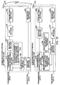
- FIG.1 is a block diagram showing a configuration example of a wireless communication system.
- CINR Carrier-to-Interference plus Noise power Ratio
- indexes indicating the reception quality associated with received signal power and/or carrier power may be used such as RSSI (Receive Signal Strength Indication), SNR (Signal to Noise power Ration), SIR (Signal to Interference power Ratio), SINR (Signal to Interference plus Noise power Ration), CNR (Carrier to Noise power Ratio), CIR (Carrier to Interference power Ratio) and the like.
- a frequency channel means one or a plurality of subcarriers, and explanations are made on scheduling in a plurality of frequency channels, but the channel to which the invention is applicable is not limited to the frequency channel.
- a frame means a transmission unit.
- the wireless communication system as shown in FIG. 1 is an OFDMA system
- a communication control apparatus 100 is a base station
- a communication terminal apparatus 200 is a mobile station
- the invention is not limited thereto.
- a side (on which the reception quality notification function is performed) for notifying the reception quality information is assumed to be the communication terminal apparatus
- a side (on which the allocation function is performed) for allocating transmission data to each channel based on the notified reception quality information is assumed to be the communication control apparatus.
- a single communication apparatus may have both the functions.
- the communication apparatus is an apparatus that performs wireless communications, and includes a base station, mobile station, wireless device, portable terminal, cellular telephone and the like.
- the invention is applicable to communication apparatuses having the relationship such that any one of a plurality of communication apparatuses executes the allocation function, and that the other communication apparatuses execute the reception quality notification function.
- the communication control apparatus 100 is provided with a transmission frame generating section 110, mapping section 120, IFFT (Inverse Fast Fourier Transport) section 130, transmitting section (control-side transmitting section) 140, antenna 150, receiving section (control-side receiving section) 160, judging section 170, and scheduler section 180.
- the communication terminal apparatus 200 is provided with an antenna 210, receiving section (terminal-side receiving section) 220, FFT (Fast Fourier Transport) section 230, judging section 240, reception quality measuring section 250, reception quality information generating section 260, transmission frame generating section 270, mapping section 280, and transmitting section (terminal-side transmitting section) 290.
- Each of components constituting the wireless communication system will be described along the flow of data. First described is the flow for transmitting transmission data (downlink transmission data) to the communication terminal apparatus 200 in the communication control apparatus 100.
- the transmission frame generating section 110 generates a transmission frame from the transmission data (downlink transmission data) according to scheduling control information notified from the scheduler section 180. At this point, the section 110 performs channel coding according to MCS (Modulation and Coding Scheme, modulation parameter) information notified from the scheduler section 180. Further, the section 110 generates control data to notify the communication terminal apparatus of the MCS information, and multiplexes the control data into the transmission frame. At this point, the control data may be notified to the communication terminal apparatus on a different channel. Further, a control symbol may be mapped and then multiplexed.
- MCS Modulation and Coding Scheme
- the mapping section 120 performs mapping of the transmission frame according to the MCS control information notified from the scheduler section 180.
- the IFFT section 130 performs inverse fast Fourier transform on a modulation symbol string generated in the mapping section 120, and thereby generates an OFDM signal.
- the transmitting section 140 transmits the OFDM signal via the antenna 150.
- the communication terminal apparatus 200 receives the transmission data (downlink transmission data) transmitted from the communication control apparatus 100, and transmits transmission data (uplink transmission data) to be transmitted.
- the receiving section 220 receives the OFDM signal transmitted from the communication control apparatus via the antenna 210.
- the FFT section 230 transforms the signal into a modulation symbol of each subcarrier.
- the reception quality measuring section 250 measures the reception quality of the received signal judged by the judging section 240.
- CINR is measured as the reception quality.
- the measured reception quality measurement result is notified to the reception quality information generating section 260.
- a specific example of the reception quality measurement result will be described later using specific examples as shown in FIGs.7 to 9 .
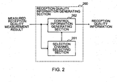
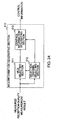
- FIG.2 is a block diagram showing an example of a configuration of the reception quality information generating section 260.
- the reception quality information generating section 260 has a selection channel selecting section 261 and control information generating section 262.
- the selection channel selecting section 261 selects selection channels based on the reception quality notified from the reception quality measuring section 250, and notifies the channels to the control information generating section 262.
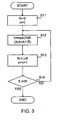
- FIG.3 is a diagram showing an example of procedures (selection channel selecting procedures) for selecting selection channels from a plurality of channels.
- the procedures for selecting selection channels adopt a method of selecting frequency channels sequentially in descending order of CINR measured in the reception quality measuring section 250. More specifically, the procedures are explained with reference to FIG.3 .
- the section 261 may select all or part of last allocated channels, and then, select selection channels using the above-mentioned selection method within the range of the number of selectable channels.
- the control information generating section 262 Based on the selection channels selected by the selection channel selecting section 261 and reception quality, to notify the communication control apparatus 100, the control information generating section 262 generates reception quality information including selection channel numbers (frequency channel numbers for identifying the selection channels, selection channel information) for identifying the selection channels, selection measurement results (selection CINR levels, selection reception quality information) indicating the reception quality (CINR) in the selection channels, and an average measurement result (average CINR level, average reception quality information) obtained by averaging the reception quality in all the frequency channels except the selection channels, and outputs the generated reception quality information to the transmission frame generating section 270.
- the selection channel number can be information for notifying the selection channel to the communication control apparatus 100 such as a channel identifier, frequency channel number or the like. The selection channel number and selection measurement result are notified in association with each other.
- the operation of the reception quality information section 260 as shown in FIG. 3 is as described above.
- the transmission frame generating section 270 generates a transmission frame from transmission data (uplink transmission data). Further, the section 270 generates control information to notify the communication control apparatus 100 of the reception quality information generated in the reception quality information generating section 260, and multiplexes the resultant into the transmission frame.
- the communication control apparatus 100 receives the transmission data (uplink transmission data) transmitted from the communication terminal apparatus 200.
- the receiving section 160 receives the transmission data transmitted from the communication terminal apparatus 200 via the antenna 150.
- the judging section 170 demodulates and decodes the transmission data received in the receiving section 160. Further, the judging section 170 separates the control information for reception quality information notification from a data portion, and outputs the reception quality information (selection channel numbers, selection measurement results and average measurement result) to the scheduler section 180.
- the allocation determining section 181 determines communication terminal apparatuses 200 to assign in all the channels.
- FIG.5 is a flowchart showing an example of the operation of the allocation determining section 181.
- the allocation determining section 181 compares the selection measurement results in the selection channels from each communication terminal apparatus 200 with one another, and assigns data of which destination is the communication terminal apparatus 200 with the highest reception quality to a band (band of the frequency channel) that is selected as the selection channel by at least one communication terminal apparatus 200 (step S21).
- the same technique as in conventional scheduling is used, and various techniques can be used.
- the maximum CIR method is adopted as an example, and as well as the method, the proportional fairness method and the like can be used.
- step S23 For the frequency channel that is not notified as the selection channel from any communication terminal apparatus 200, such a channel is allocated based on the average measurement result notified from each communication terminal apparatus 200.
- last assigned communication terminal apparatus 200 may be assigned preferentially, or arbitrary frequency channels are allocated in the predetermined order of communication terminal apparatuses as in RR (Round Robin) (step S23). Until allocation of all the bands is finished, or allocation of all the data is finished, step S23 is repeated (No in step S24).
- the allocation determining section 181 completes allocation of each frequency channel or each data (Yes in step S24)
- the section 181 notifies scheduling control information indicating the allocation to each band (each frequency channel) to the MCS selecting section 182 and transmission frame generating section 110 (step S25).
- the MCS selecting section 182 selects MCS of the data to be transmitted to each of assigned communication terminal apparatuses 200 based on the reception quality information of the assigned communication terminal apparatuses in respective allocated channels, and outputs the MCS control information to the transmission frame generating section 110 and mapping section 120.
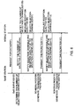
- FIG.6 is a sequence diagram snowing an example of data transmission and reception between the base station and the mobile station in the first embodiment.
- the mobile station requests data such as control information including the number of selection channels and the like (step S101).
- the base station performs a QoS (Quality of Service) survey (step S102), determines the number of selection channels based on the transmission data requested to the scheduler section 180 (based on the QoS such as the amount, priority and the like) (step S103), and notifies the number of selectable channels (step S104).
- QoS Quality of Service
- the mobile station notifies (sets) the selection channel selecting section 261 of (at) the number of selectable channels (step S105), the reception quality measuring section 250 measures the reception quality (step S106), and the reception quality information generating section 260 selects selection channels, and generates the reception quality information (step S107).
- the mobile station notifies the base station of the generated reception quality information (selection channels and reception quality of the selection channels) (step S108).
- the scheduler section 180 performs scheduling (step S109), transmission frame generating section 110 and the like generate transmission packets (step S110), and the generated transmission packets are transmitted to the mobile station (step S111). Based on the number of selectable numbers last notified (step S105), the mobile station measures the reception quality (step S112), selects selection channels (step S113), and notifies the reception quality information (step S114). Subsequent operations are repetitions of the foregoing and omitted.
- the communication terminal apparatus 200 Since the communication terminal apparatus 200 is required to notify the communication control apparatus 100 only of the reception quality information in the selection channels, as compared with the case of notifying the reception quality information of all the frequency channels, overhead due to control information notification is reduced on uplink.
- the method of selecting selection channels in the mobile station that is an example of the communication terminal apparatus 200
- the scheduling method in the base station that is an example of the communication control apparatus 100.
- FIG.7 is a diagram showing an example of the reception quality information notified to the base station from a mobile station A.
- FIG.7 shows an example of uplink reception quality information in the case where the mobile station A notifies two frequency channels as selection channels.
- the mobile station notifies information of Ch2 and Ch5 (selection channel numbers) that are frequency channel numbers (channel identifiers) for identifying the frequency channels selected as the selection channels, "2" and "8" that are CINR levels (selection CINR levels) in respective frequency channels, and "2" that is an average CINR level.
- the CINR level is a value obtained by quantizing a CINR measurement value that is measured reception quality.
- the base station is notified of the reception quality information from each mobile station. Such a manner is shown in FIGs.8A to 8C .
- FIGs.8A to 8C are diagrams showing an example of the process of scheduling in the base station.
- FIGs.8A to 8C show the case where the base station is notified of the reception quality information from three mobile stations, A, B and C.
- the vertical axis represents the CINR value (value of the CINR level)
- the horizontal axis represents the frequency (frequency channel number).
- different kinds of lines are used to distinguish between mobile stations to represent data, while the solid line represents data associated with the mobile station A, the dashed line represents data associated with the mobile station B, and the dotted line represents data associated with the mobile station C.
- FIG.8A shows an example of CINR level distribution in the selection channels notified from respective mobile stations.
- the mobile station A notifies Ch2 and Ch5 as the selection channels
- the mobile station B notifies Ch3 and Ch5 as the selection channels
- the mobile station C notifies Ch6 and Ch7 as the selection channels.
- Ch5 is selected by two mobile stations, A and B.
- the base station assigns a mobile station in each requested selection channel (step S21 and step S22 in FIG.5 ). At this point, a frequency channel that is requested from only one mobile station is allocated to data of which destination is the mobile station. Further, in the case where a plurality of mobile stations requests the same frequency channel, the base station allocates the frequency channel to data of which destination is a mobile station with the best reception quality, i.e.
- the base station preferentially assigns data of which destination is the mobile station last assigned to the frequency channel.
- the allocation of the frequency channel is performed in such a method.
- the base station allocates Ch5 to the mobile station A.
- the frequency channel that is not selected is preferentially allocated to data of which destination is the mobile station that is assigned to the channel last time. This is because it is considered that the last assigned mobile station has a high possibility that the reception quality in the frequency channel is relatively good.
- the frequency channel is allocated based on a factor such that the frequency channel is not used, the power can efficiently be used, interference can be suppressed, or the like. The number of frequency channels to allocate to a mobile station is determined by the data amount and the like.
- FIGs. 9A to 9C are diagrams showing an example of the process of selecting selection channels in a mobile station D.
- the reception quality measuring section 250 in the mobile station D measures the reception quality (CINR), and quantizes the measured CINR measurement value to calculate a CINR level.
- FIG.9A is a diagram showing the CINR measurement value and CINR level. The dashed line shows the CINR measurement value obtained by the reception quality measuring section 250 measuring CINR (reception quality), and each of the solid lines shows a value of the CINR level obtained by quantizing the CINR measurement value for each frequency channel.
- the selection channel selecting section 261 of the reception quality information generating section 260 compares the CINR level in each measured frequency channel with one another as shown in FIG.9A , and thereby selects frequency channels to select as selection channels.
- the selection channel selecting section 261 sequentially selects frequency channels with higher CINR in the range of the number of selectable channels beforehand notified from the base station.
- the control information generating section 262 uses the result of selection of the selection channel selecting section 261, the control information generating section 262 generates selection CINR levels (selection measurement results) of the selection channels, and the average CINR level (average measurement result).
- FIG.9B is a diagram showing the CINR level (selection CINR level) of the selected selection channel and a value of the average CINR level.
- the communication terminal apparatus is capable of selecting part of frequency channels from all the frequency channels, and notifying the communication control apparatus of the reception quality information of selected frequency channels. As compared with the case of notifying the reception quality information of all the frequency channels, it is possible to suppress control information amounts, and to reduce overhead due to notification of the control information. Further, since the communication terminal apparatus notifies the communication control apparatus of the reception quality information with good reception quality, it is possible to notify the communication control apparatus of the frequency channels with good reception quality. The communication control apparatus assigns the frequency channels selected in the communication terminal apparatus, and is thereby capable of allocating the frequency channels with good reception quality. Further, since the communication control apparatus notifies the communication terminal apparatus of the number of selectable channels, it is possible on the communication control apparatus side to adjust reception quality information amounts notified from the communication terminal apparatus corresponding to the communication status.
- the transmission frame generating section 110 generates a transmission frame from the transmission data according to the scheduling control information notified from the scheduler section 180. At this point, the section 110 performs channel coding according to the MCS information notified from the scheduler section 180. Further, in addition to the control data to notify the communication terminal apparatus 200 of the MCS information, the section 110 generates the control data to notify the communication terminal apparatus 200 of the scheduling control information, and the control data to notify each communication terminal apparatus 200 of the reception quality information (allocation measurement result, allocation CINR level) in the frequency channels allocated to each communication terminal apparatus 200, and multiplexes the control data into the transmission frame.
- the allocation measurement result is a reception quality measurement result measured by a communication terminal apparatus assigned to each channel.
- the mapping section 120 performs mapping of the transmission frame according to the MCS control information notified from the scheduler section 180.
- the IFFT section 130 performs inverse fast Fourier transform on a modulation symbol string generated in the mapping section 120, and thereby generates an OFDM signal.
- the OFDM signal is transmitted via the transmitting section 140.
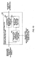
- FIG.10 is a block diagram showing an example of a configuration of the reception quality information generating section 260 .
- the reception quality information generating section further has a reception quality difference calculating section 263, in addition to the selection channel selecting section 261 and control information generating section 262 as shown in FIG.2 .
- the selection channel selecting section 261 selects selection channels to notify the control information generating section 262. For example, the selection channel selecting section 261 selects, as selection channels, channels corresponding to the number of selectable channels in descending order of the reception quality difference (in descending order of excellence of the reception quality measurement result of the communication terminal apparatus). Alternately, the selection channel selecting section 261 selects, as selection channels, channels with the calculated reception quality difference larger than a predetermined threshold. Further, the section 261 assigns a priority to a channel that is allocated to the communication terminal apparatus last time to select as the selection channel among the channels with the calculated reception quality difference larger than the predetermined threshold.
- the transmission frame generated in the transmission frame generating section 270 undergoes mapping in the mapping section 280, and is transmitted to the communication control apparatus 100 via the transmitting section 290.
- the receiving section 160 receives the transmission data (signal) transmitted from the communication terminal apparatus 200, and the judging section 170 demodulates and decodes the data.
- the judging section 170 separates the control information to notify the reception quality information from a data portion, and outputs the reception quality information (selection channel numbers, selection measurement results and average measurement result) to the scheduler section 180.
- FIG.11 is a block diagram showing an example of a configuration of the scheduler section 180 of this embodiment.
- the data flow differs from that in the block portion of FIG.4 .
- the scheduler section 180 has the allocation determining section 181 and MCS selecting section 182.
- the MCS selecting section 182 selects MCS of the data to be transmitted to each of assigned communication terminal apparatuses 200 based on the reception quality information of the assigned communication terminal apparatuses in respective allocated channels, and outputs the MCS control information to the transmission frame generating section 110 and mapping section 120.
- the allocation determining section 181 of the scheduler section 180 When the base station determines the allocation, the allocation determining section 181 of the scheduler section 180 generates CINR information (allocation CINR information) in the allocated frequency channels.
- the allocation CINR information is an example of the allocation measurement result.
- FIG.12 shows an example of descriptions of the CINR information in the allocated frequency channels.
- the base station notifies each mobile station of the information of the CINR level in each frequency channel.
- FIGs.13A to 13D show examples of the process of selecting selection channels in a mobile station E using the allocation CINR information.
- FIG.13A is a diagram showing the CINR measurement value and CINR level.
- the dashed line shows the CINR measurement value obtained by the reception quality measuring section 250 measuring CINR (reception quality), and each of the solid lines shows a value of the CINR level obtained by quantizing the CINR measurement value for each frequency channel.
- FIG. 13B is a diagram showing an example of the CINR information in the frequency channels allocated to a plurality of mobile stations.
- Each of the solid lines shows a value of the CINR level of the frequency channel allocated to the mobile station E, and each of the doted lines shows a value of the CINR level of the frequency channel allocated to the mobile station except the mobile station E.
- the mobile station E is assigned frequency channels Ch2, Ch5 and Ch8, and the other frequency channels are allocated to other mobile stations.
- the reception quality information generating section 260 compares the information of the CINR level in each frequency channel notified from the base station as shown in FIG.13B with the measured CINR level in each frequency channel as shown in FIG.13A , and selects selection channels.
- FIG.14 is a flowchart showing an example of the operation of selecting selection channels. The operation of FIG.14 is based on the premise that the number of selection channels (the number of selectable channels) N is beforehand determined.
- the reception quality difference calculating section 263 calculates a CINR difference by subtracting a value of the allocation CINR level from a value of the CINR level of the mobile station E for each of the frequency channels (step S31). Based on the CINR difference of the reception quality difference calculating section 263, the selection channel selecting section 261 extracts a frequency channel that is allocated to the station E last time and that does not undergo judgment of step S33 and subsequent steps (Yes in step S32), and selects a frequency channel with the highest CINR difference (i.e. an increase in the CINR level from the last time being the largest) among extracted frequency channels (step S33).
- step S34 When a value of the CINR difference in the selected frequency channel is larger than a certain level (Yes in step S34), the selected frequency channel is added (step S35). When a value of the CINR difference in the selected frequency channel is less than or equal to the certain level (No in step S34), the processing flow proceeds to step S37. Step S32 to step S36 are repeated until the number of selected frequency channels becomes a limitation value N, and when there is no frequency channel in step S32 that is allocated last time and that does not undergo judgment of step S33 and subsequent steps (No in step S32), the processing flow shifts to step S37.
- the selection channel selecting section 261 selects a frequency channel with the highest CINR difference (i.e. a value obtained by subtracting the CINR level of the station E from the CINR level of another mobile station being the largest) among frequency channels that are not allocated last time (step S37), and adds the frequency channel to selected frequency channels (step S38).
- Step S37 to step S39 are repeated until the number of selected frequency channel becomes the limitation value N.
- the processing is finished.
- step S32 to step S36 are processing associated with the frequency channel that is allocated last time
- step S37 to step S39 are processing associated with the frequency channel that is not allocated last time.
- a frequency channel that is allocated (or selected) last time is preferentially selected.
- FIG.13C is a diagram showing a value of the CINR difference of a frequency channel that is allocated last time
- FIG.13D is a diagram showing a value of the CINR difference of a frequency channel that is not allocated last time.
- the dashed line shows a level of a predetermined (certain) level.
- a value of the CINR difference is larger than a predetermined (certain) level in a frequency channel that is allocated (or selected) last time
- the frequency channel is selected again (step S34 in FIG.14 ).
- channels are selected in descending order of the CINR difference in step S33 of FIG. 14
- ch5 is first selected in FIG.13C .
- Ch2 and Ch8 are not selected because their values of the CINR difference are less than the predetermined level.
- a difference between the CINR level based on the CINR measurement value and the CINR level notified as the allocation CINR information from the base station is calculated as the CINR difference in each of the frequency channels, and frequency channels are selected sequentially in descending order of the CINR difference.
- Ch6 and Ch1 are selected in this order.
- the limitation value N of frequency channels is assumed to be two, Ch5 and Ch6 are selected in this order.
- the communication terminal apparatus since the communication terminal apparatus is required to notify the communication control apparatus of the reception quality only in the selected frequency channels, overhead due to control information notification is reduced on uplink. Further, the communication control apparatus 100 notifies the reception quality information in frequency channels allocated to the communication terminal apparatus 200, the communication terminal apparatus 200 compares the notified reception quality information with the measured reception quality information, and requests frequency channels having a high possibility of being allocated to the communication control apparatus, and it is thereby possible to reduce the control information efficiently.
- the following example describes an aspect where the communication control apparatus selects an allocation change candidate channel, and notifies the communication terminal apparatus of the reception quality information in the allocation change candidate channel.
- the scheduler section 180 performs the operation of the data flow as shown in FIG.11 , and notifies the allocation measurement result to the transmission frame generating section 110, and further to the allocation change candidate channel selecting section 310.
- the allocation change candidate channel selecting section 310 selects a channel (allocation change candidate channel) such that changing allocation to the channel is preferable (desirable), based on the allocation measurement result notified from the scheduler section 180.
- the allocation measurement result is the reception quality measurement result (CINR level) notified to the communication control apparatus 300 from the communication terminal apparatus 200 assigned to each channel. More specifically, the allocation change candidate channel is judged based on the CINR level and selected as described below.
- the allocation change candidate channel selecting section 310 selects an allocation change candidate channel by an either method as described below, using a beforehand set threshold of the CINR level, a beforehand set number-of-channel limitation value of the allocation change candidate channel, or both of them.
- the threshold and number-of-channel limitation value are assumed to be held in a memory area inside the allocation change candidate channel selecting section 310.
- the allocation change candidate channel selecting section 310 outputs an allocation change candidate channel number (frequency channel number, allocation change candidate channel information) for identifying the selected allocation change candidate channel and the reception quality measurement result (CINR level) in the selected allocation change candidate channel to the transmission frame generating section 110.
- the transmission frame generating section 110 Based on the information output from the allocation change candidate channel selecting section 310, the transmission frame generating section 110 generates the control information to notify the communication terminal apparatus 200 of the allocation change candidate channel number and the reception quality measurement result in the allocation change candidate channel, and multiplexes the information into a transmission frame.
- step S31 in FIG.14 the step of calculating the CINR difference in all the frequency channels is changed to a step of calculating the CINR difference in the allocation change candidate channels notified from the communication control apparatus 300, and the same selection method as in FIG. 4 can thereby be applied.
- the reception quality information generating section 260 makes the above-mentioned determination, and generates the reception quality information including a result of the above-mentioned determination.
- the reception quality information generating section 260 may generate the reception quality information further including the reception quality measurement results (last selection measurement results, last selection CINR levels) in frequency channels that are allocated last time to the communication terminal apparatus 200, in addition to the information (selection channel number) indicating a selection channel selected from the allocation change candidate channels, and the reception quality measurement result (selection measurement result, selection CINR level) in the selection channel.
- the communication control apparatus is capable of notifying the communication terminal apparatus of the information on allocation change candidate channels. Further, the communication terminal apparatus is capable of selecting a frequency channel of which allocation is desired from the notified allocation change candidate channels, and notifying the communication control apparatus of the channel as the selection channel. By selecting a selection channel from the change candidate channels, it is possible to make the allocation corresponding to the reception quality in the entire system. Further, by this means, it is possible to suppress downlink control information amounts and uplink information amounts. Accordingly, it is possible to perform efficient scheduling, while suppressing the downlink control information amounts and the uplink control information amounts.
- the communication terminal apparatus notifies the communication control apparatus of frequency channels with good reception quality as selection channels.
- Another example describes an aspect of notifying a frequency channel (allocation refusal channel) with poor reception quality.
- the allocation refusal channel is a channel to which the communication terminal apparatus refuses to being assigned.
- FIGs.16A to 16C are diagrams showing an example of the process for selecting selection channels and an allocation refusal channel in a mobile station F.
- FIG.16A is a diagram showing the CINR measurement value and CINR level.
- the dashed line shows the CINR measurement value, and each of the solid lines shows a value of the CINR level.
- FIG.16B is a diagram showing selection channels and allocation refusal channels.
- FIG.16C is a diagram showing an example of the reception quality information.
- selection channel numbers selection channel numbers
- selection reception quality information in addition to selected frequency channel numbers (selection channel numbers) and selection reception quality information in the selected frequency channels, such information is notified that is associated with an allocation refusal channel number (allocation refusal channel information) for identifying a channel to which assignment is refused, i.e. the information on a frequency channel with poor reception quality.
- allocation refusal channel information allocation refusal channel information for identifying a channel to which assignment is refused, i.e. the information on a frequency channel with poor reception quality.
- the average measurement result is not shown in FIG.16C , but may be added.
- the allocation determining section 181 of the communication control apparatus performs scheduling so as not to allocate a frequency channel to which a communication terminal apparatus refuses to being assigned to data of which destination is the communication terminal apparatus.
- the communication terminal apparatus since the communication terminal apparatus notifies the communication control apparatus of a frequency channel to which the communication terminal apparatus refuses to being assigned, the communication terminal apparatus can avoid from being assigned to the frequency channel with extremely poor reception quality.
- the communication control apparatus when selection channels are not allocated, the communication control apparatus performs the allocation using the average reception quality information (average CINR level) as an index, and therefore, there is a possibility of being assigned to a frequency channel with the CINR level remarkably falling below the average CINR level.
- the communication terminal apparatus can avoid from being assigned to a frequency channel with an extremely poor CINR level, and it is possible to perform more efficient scheduling.
- the following example describes an aspect of scheduling in consideration of QoS (Quality of Service) in addition to the reception quality information.
- QoS Quality of Service
- This example uses two classes, Real Time (RT) and Non Real Time (NRT), as an example of QoS, to explain, but the items are of an example and do not limit meaning of QoS. Further, this embodiment is explained using the OFDMA system as in FIG. 1 , but is applicable to each of the above-mentioned embodiments.
- FIG.17 shows a flowchart showing an example of scheduling of this example.
- the scheduler section 180 has the same internal blocks as in FIG.4 .
- the scheduler section 180 monitors QoS of data to assign to each frequency channel, and determines whether the data to assign is RT or NRT.
- the scheduler section 180 preferentially assigns data of RT class to channels (step S41), and after finishing the allocation of channels to all the data of RT class (Yes in step S42), assigns data of NRT class to remaining channels (step S43).
- the same technique can be used as the method described in the first embodiment.
- frequency channels selected by communication terminal apparatuses 200 are allocated based on the selection measurement results (selection CINR levels) in the selection channels notified from the communication terminal apparatuses 200, and frequency channels that are not selected by any of communication terminal apparatuses are allocated based on the average measurement results (average CINR levels) notified from the communication terminal apparatuses 200.
- the following example describes an aspect of the method of selecting selection channels in consideration of QoS.
- two classes, high priorities and low priorities are set as an example of QoS, and descriptions are made using two classes.
- the classes are of an example, and do not limit meaning of QoS.
- two or more classes may be set, or elements other than the priority may be used.
- This embodiment is explained using the OFDMA system as in FIG.1 , but is applicable to each of the above-mentioned examples.
- the scheduler section 180 of the communication control apparatus 100 determines the number of selectable frequency channels as selection channels for each data from QoS of the data to transmit to the communication terminal apparatus 200, and notifies the number to the communication terminal apparatus 200. For example, settings are made so that the number of selectable frequency channels is three for high-priority data, and that the number of selectable frequency channels is one for low-priority data.
- the communication terminal apparatus 200 selects frequency channels in the range of the number of frequency channels notified from the communication control apparatus 100 in requesting the frequency channels to the communication control apparatus 100. At this point, as described in the first embodiment, channels with good reception quality measurement results may be selected in the range of the number of selectable frequency channels.
- the number of channels allocated to high-priority data is relatively higher than the number of channels allocated to low-priority data, and QoS is thereby satisfied.
- this example describes the example of setting two classes on the priority, but is applicable in the case where the number of selectable frequency channels is set corresponding to QoS (for example, priority).
- QoS for example, priority
- the number of selectable frequency channels is set corresponding to another element of QoS, and that QoS is divided into a plurality of stages to set the number of selectable frequency channels by stage (by level), or the like.
- the following example describes an aspect that the communication control apparatus controls the number of frequency channels that the communication terminal apparatus notifies as selection channels, and notifies the number to the communication terminal apparatus.
- the communication terminal apparatus requests data (step S101), the communication control apparatus notifies the number of selectable channels (step S104), and the communication terminal apparatus selects frequency channels corresponding to the notified number of selectable channels as selection channels, and notifies the selection channels and selection measurement results to the communication control apparatus (step S105 to step S108).
- the communication control apparatus performs statistical processing based on the communication status, and controls the number of selectable channels.
- FIG.19 is a block diagram showing an example of a configuration of the statistical processing section 410.
- the statistical processing section 410 has a ratio calculating section 411, number-of-selectable channel controlling section 412, and threshold storing section 413.
- the ratio calculating section 411 calculates a ratio between the number of allocated channels and the number of channels allocated to the communication terminal apparatus 200, among selection channels selected by the communication terminal apparatus 200.
- the number-of-selectable channel controlling section 412 controls (adjusts) the number of selectable channels based on the calculation result calculated by the ratio calculating section 411.
- FIG.20 is a flowchart showing an example of the operation of the statistical processing section 410.
- the operations of the ratio calculating section 411 and number-of-selectable channel controlling section 412 are described with reference to FIG. 20.
- FIG. 20 uses the number of selectable channels N, the number of allocated channels N alloc , a set of allocated channels X alloc , the number of selection channels N req , an nth element r n of the set of selection channels, first threshold D 1 , second threshold D 2 , calculation result d, and counter n, k.
- n is a variable indicating a number of r n of the set of selection channels
- k is a variable to count the number of channels allocated to the communication terminal apparatus 200 among the selection channels.
- the first threshold D 1 and second threshold D 2 are thresholds (calculation result thresholds) for judging the calculation result.
- the ratio calculating section 411 initializes the counter n, k, and based on the scheduling control information, extracts the number of channels N alloc allocated to transmission data of which destination is each communication terminal apparatus 200 and a set of allocated channels X alloc (step S51).
- the section 411 compares the set of allocated channels X alloc with the nth element r n of the set of selection channels sequentially, and counts the number of channels k allocated to the communication terminal apparatus 200 among the set of selection channels (step S52 to step S55). By this means, the section 411 extract the number of allocated channels k among frequency channels (selection channels) selected by each communication terminal apparatus 200.
- the number-of-selectable channel controlling section 412 reads the thresholds D 1 and D 2 from the threshold storing section 413, and maintains a value of the number of selectable channels N when the calculation result d is larger than the first threshold D 1 (Yes in step S57), while being smaller than the second threshold D 2 (Yes in step S58).
- the section 412 adds "1" to the number of selectable channels N (step S59).
- the section 412 subtracts "1" from the number of selectable channels N (step S60).
- the section 412 outputs the determined number of selectable channels N to the transmission frame generating section 110 as the number-of-selectable control channel information.
- the numeric value of "1" to add or subtract is an example, other numeric values may be used, or the numeric value to add or subtract may be varied corresponding to a difference from the threshold.
- FIG.21 is a sequence diagram showing an example of data transmission and reception between the base station (an example of the communication control apparatus 400) and mobile station (an example of the communication terminal apparatus 200).
- the mobile station requests data such as the control information including the number of selectable channels and the like (step S701).
- the base station performs a QoS survey (step S702), and the statistical processing section 410 determines the number of selectable channels (step S703), and notifies the number of selectable channels (step S704).
- the mobile station notifies the number of selectable channels to the selection channel selecting section 261 (step S705), the reception quality measuring section 250 measures the reception quality (step S706), and the reception quality information generating section 260 selects selection channels, and generates the reception quality information (step S707).
- the mobile station notifies the base station of the generated reception quality information (selection channels and the reception quality of the selection channels) (step S708).
- the calculation method of the ratio calculating section 411 as shown in FIG.21 is an example, and other calculation methods may be used.
- the calculation result d may be a value obtained by dividing the number of selection channels N req by the number of allocated channels N alloc .
- the ratio calculating section 411 may hold information of at least one of the scheduling control information, selection channel numbers and calculation results each of a plurality of previous times, or a combination of any of them, and calculate the calculation result by considering the information of the plurality of previous times.
- the following example describes an aspect where the communication terminal apparatus notifies the communication control apparatus of information associated with a transmission rate such as the MCS information and the like as the reception quality.
- FIG.22 is a block diagram showing a configuration example of an OFDMA system.
- the OFDMA system as shown in FIG. 22 is comprised of the communication control apparatus 100 and communication terminal apparatus 500, and has the components of FIG.1 and an MCS information generating section 510 added to the communication terminal apparatus 500 as a substitute for the reception quality information generating section 260.
- FIG.1 portions differing from FIG.1 will be focused below to explain.
- the components assigned the same reference numerals and names as in FIG.1 have the same functions, and descriptions thereof are omitted.
- the scheduler section 180 of the communication control apparatus has the MCS selecting section 182, and selects MCS based on the reception quality information notified from the communication terminal apparatus.
- the MCS selecting function is provided on the communication terminal apparatus side.
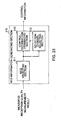
- FIG.23 is a block diagram showing an example of a configuration of the MCS information generating section 510
- FIG.24 is a block diagram showing an example of a configuration of the MCS information generating section 510 different from that in FIG.23
- the MCS information generating section 510 has an MCS selecting section 511, selection channel selecting section 512 and control information generating section 513. The flow of data is different between FIG.23 and FIG.24 .
- the MCS selecting section 511 selects MCS based on the reception quality measurement result in each frequency channel measured by the reception quality measuring section 250, and notifies the selected MCS to the selection channel selecting section 512 and control information generating section 513.
- the MCS selecting section 511 selects MCS for all the frequency channels.
- the selection channel selecting section 512 selects frequency channels with higher levels of MCS i. e. frequency channels expected to provide higher transmission rates as selection channels, and notifies the control information generating section 513 of frequency channel numbers of the selected selection channels and reception quality measurement results measured by the reception quality measuring section 250.
- the control information generating section 513 generates the control information including the frequency channel numbers of the selection channels selected by the selection channel selecting section 512, and the information of MCS of the selection channels selected by the selection channel selecting section 512.
- the selection channel selecting section 512 selects selection channels from the channels in descending order of the reception quality measurement result in each frequency channel measured by the reception quality measuring section 250, and notifies the MCS information selecting section 511 of the frequency channel numbers of the selected selection channels, while further notifying the control information generating section 513 of the frequency channel numbers of the selected selection channels and reception quality measurement results measured by the reception quality measuring section 250.
- the MCS selecting section 511 selects MCS of the frequency channels selected as the selection channels by the selection channel selecting section 512, and notifies the control information generating section 513 of the information of selected MCS together with the frequency channel numbers.
- the control information generating section 51 generates the control information including the frequency channel numbers of the selection channels, and MCS of the selection channels selected.
- FIG.25 is a diagram showing an example of a configuration of the scheduler section 180 of this embodiment.
- the scheduler section 180 has the allocation determining section 181, and the allocation determining section 181 receives the reception quality information and MCS information of selection channels as its input, performs scheduling based on the reception quality information, and based on the scheduling result, associates the MCS information notified from the communication terminal apparatus 500 with the allocated frequency channel to notify the transmission frame generating section 110 and mapping section 120.
- the communication terminal apparatus is capable of selecting MCS while selecting selection channels based on the MCS information. It is thereby possible to designate MCS on the communication terminal apparatus side.
- each communication terminal apparatus selects selection channels, by using as an allocation measurement result the MCS information notified to each communication terminal apparatus from the communication control apparatus.
- the communication control apparatus notifies the communication terminal apparatus of allocation information in each frequency channel, and MCS for each communication terminal apparatus in each frequency channel, and the communication terminal apparatus extracts data symbols to the communication terminal apparatus based on the scheduling information after the FFT processing, and performs demodulation and decoding processing based on the notified MCS information.
- the reception quality measuring section 250 measures the reception quality in each frequency channel.
- the MCS selecting section 511 selects (calculates) the MCS level meeting predetermined quality from the reception quality measurement result in each frequency channel.
- the selection channel selecting section 512 compares the MCS level selected in the MCS selecting section 511 with each of the MCS levels of all the channels notified from the communication control apparatus 100, and selects a channel such that the MCS level obtained from the measurement value (the reception quality measurement result of the communication terminal apparatus) is higher than the MCS level notified from the communication control apparatus 100.
- the MCS level is set according to accuracy of the quality of MCS
- a numeric value corresponding to each MCS level is beforehand set
- channels are sequentially selected in descending order of a value obtained by subtracting a value corresponding to the MCS level of respective one of all the channels notified from the communication control apparatus from a numeric value corresponding to the MCS level obtained from the measurement value.
- channels are sequentially selected in descending order of a value obtained by dividing the numeric value corresponding to the MCS level obtained from the measurement value by the value corresponding to the MCS level of respective one of all the channels notified from the communication control apparatus.
- the communication terminal apparatus After selecting the selection channels, the communication terminal apparatus transmits the control information including the information indicating the selection channels and the information indicating the MCS levels in the selection channels to the communication control apparatus.
- the communication terminal apparatus is capable of selecting selection channels using the MCS information notified from the communication control apparatus. It is thereby possible to suppress the downlink control information.
- FIG.26 is a diagram showing an example of a transmission frame of this example.
- a channel divided in the time domain in a transmission frame in the embodiment is called a sub-channel, and different transmission data is assigned to each sub-channel.
- transmission data is selected of which destination is a communication terminal apparatus with good reception quality, for each channel.
- a selected channel is a channel to be divided into a plurality of sub-channels
- communication terminal apparatuses are selected in descending order of excellence of the reception quality in the divided channel corresponding to the number of multiplexable communication terminal apparatuses, and the sub-channels are allocated to the transmission data of which destinations are respective communication terminal apparatuses.
- a plurality of channels that are not notified as selection channels from any communication terminal apparatuses may be collected, divided into a plurality of sub-channels, and allocated to transmission data of which destinations are communication terminal apparatuses with poor reception quality.
- the channel may be divided so that the sub-channel has an equal number of symbols, or the capacity of a sub-channel may be varied so as to allocate a sub-channel containing a higher number of symbols to a communication terminal apparatus having an high average value of the reception quality.
- a plurality of communication terminal apparatuses uses a single channel, and it is thereby possible to obtain the frequency diversity effect.
- the transmission equality can thereby be improved.
- the following example describes a case that the number of selectable channels is not notified to the communication terminal apparatus from the communication control apparatus and that a beforehand determined number is used, or an aspect where the number of selectable channels is determined on the communication terminal apparatus side.
- Each of the above-mentioned examples describes the case where the communication control apparatus determines the number of selectable channels to beforehand (periodically, or whenever varying the number of selectable channels) notify the communication terminal apparatus.
- the communication control apparatus does not need to always notify the number of selectable channels.
- the communication terminal apparatus is capable of using a beforehand set value as the number of selectable channels.
- the communication terminal apparatus is capable of determining the number of selectable channels in the method as described above.
- the communication terminal apparatus may beforehand hold a threshold (measurement result threshold) that is a criterion of the reception quality measurement result, and select, as selection channels, channels exceeding the measurement result threshold among the reception quality measurement results measured by the reception quality measuring section 250.
- a threshold measurement result threshold
- the communication terminal apparatus may use a technique for selecting only frequency channels exceeding the measurement result threshold even when the number of the frequency channels does not reach the number of selectable channels, or selecting frequency channels corresponding to the number of selectable channels even when the number of frequency channels exceeding the measurement result threshold does not reach the number of selectable channels. Further, the communication terminal apparatus may use a technique for selecting frequency channels exceeding the measurement result threshold corresponding to the number of selectable channels or less.
- the following example describes an aspect where the communication terminal apparatus varies the number of selectable channels.
- FIG.27 is a block diagram showing a configuration example of an OFDMA system of the example.
- the OFDMA system as shown in FIG.27 is comprised of the communication control apparatus 100 and communication terminal apparatus 600, and has the components of FIG.1 and a statistical processing section 610 added to the communication terminal apparatus 600.
- FIG.1 portions differing from FIG.1 will be focused below to explain.
- the components assigned the same reference numerals and names as in FIG.1 have the same functions, and descriptions thereof are omitted.
- the statistical processing section 610 has the same configuration as that of the statistical processing section 410 provided in the communication terminal apparatus 400 as shown in FIG.19 to perform the same processing, and specific descriptions thereof are omitted.
- the statistical processing section 610 receives respective pieces of information from components as described below.
- the judging section 240 notifies the statistical processing section 610 (ratio calculating section) of the judged scheduling control information.
- the reception quality information generating section 260 notifies the statistical processing section 610 (ratio calculating section) of selection channels numbers (frequency channel numbers for identifying selection channels selected by the selection channel selecting section 261). Based on the notified information, the statistical processing section 610 performs the same processing as in FIG. 20 , determines the number of selectable channels, and notifies the determined number of selectable channels to the selection channel selecting section 261 of the reception quality information generating section 260.
- the number of requested channels may be varied by changing the measurement result threshold as described in the previous example.
- the statistical processing section 610 compares the calculated calculation result with the first threshold D 1 (calculation result threshold used in FIG. 20 ), and varies the measurement result threshold to decrease when the calculated calculation result is smaller than the first threshold D 1 . Further, the statistical processing section 610 compares the calculated calculation result with the second threshold D 2 (calculation result threshold used in FIG. 20 ), and varies the measurement result threshold to increase when the calculated calculation result is larger than the second threshold D 2 .
- the selection channel selecting section 261 selects selection channels based on the measurement result threshold varied in the statistical processing section 610.
- the number of frequency channels with the reception quality exceeding the threshold increases by decreasing the measurement result threshold, while the number of frequency channels with the reception quality exceeding the threshold decreases by increasing the measurement result threshold, and the communication terminal apparatus and communication control apparatus are thereby capable of obtaining the same effect as in varying the number of selectable channels.
- the communication terminal apparatus may use a technique for selecting only frequency channels exceeding the measurement result threshold even when the number of the frequency channels does not reach the number of selectable channels, or selecting frequency channels corresponding to the number of selectable channels even when the number of frequency channels exceeding the measurement result threshold does not reach the number of selectable channels. Further, the communication terminal apparatus may use a technique for selecting frequency channels exceeding the measurement result threshold corresponding to the number of selectable channels or less.
- the communication control apparatus may determine the number of selectable channels based on the priority of data to request transmission thereof. In addition, the control of the number of selectable channels in the communication control apparatus is described in the sixth embodiment as described previously.
- Each of the above-mentioned examples describes the case where the communication terminal apparatus selects selection channels, and reports the information indicating the reception quality measurement result itself as the information indicating the reception quality measurement result, in reporting to the communication control apparatus the reception quality information including the selection channel information for identifying the selection channels, and the information indicating the reception quality measurement results in the selection channels.
- This embodiment describes a case of reporting, as the information indicating the selection channel measurement result, the reception quality information including information indicating the reception quality measurement result (difference reference value) itself of at least one channel, and information indicating difference information of the reception quality measurement results of a plurality of channels and the difference reference value.
- the communication control apparatus and the communication terminal apparatus of this example are capable of using each component described in each of the above-mentioned examples.
- this example describes the case of generating the reception quality information using the reception quality measurement result itself of Ch2, and the difference in the reception quality measurement result between Ch2 and Ch5, but a combination of a selection channel to report the reception quality measurement result itself and a selection channel to report the difference is not limited thereto.
- the reception quality may be generated using the reception quality measurement result itself of Ch5, and the difference in the reception quality measurement result between Ch5 and Ch2.
- the communication terminal apparatus reports the reception quality information including the information indicating the measurement result itself of at least one selection channel, and the information indicating the difference information of the reception quality measurement results of a plurality of channels, and that the communication control apparatus is capable of decoding the reception quality measurement result in each selection channel.
- a selection channel to notify its reception quality measurement result itself is selected as a channel (reference channel) to be the reference, and a difference (difference value) between the reception quality measurement result (reference measurement result, difference reference value) of the selected reference channel and each of the reception quality measurement results of the other selection channels is notified as the information to notify the reception quality results of the other selection channels, but when an average measurement value (average CINR) obtained by averaging the reception quality measurement values is calculated, the average measurement value can be used as the difference reference value as a substitute for the reception quality measurement result of the channel to be the reference.
- the reception quality information is generated by calculating a difference between the reception quality measurement result and average measurement result in each selection channel.
- a difference reference value (reference measurement result) as the reference in calculating the difference does not need to be always notified from the communication terminal apparatus to the communication control apparatus.
- a predetermined value may be determined in the system in advance, or either the communication control apparatus or the communication terminal apparatus may first notify the difference reference value to the communicating party, and then, the difference may be calculated using the notified difference reference value. For example, after once notifying a reception quality measurement value of an arbitrary channel as a difference reference value, for the arbitrary channel, when the reception quality measurement value is notified next, a difference from the notified difference reference value may be notified.
- the reception quality information generating section calculates a difference value between the reception quality measurement value in the selection channel and the difference reference value as the reference of the reception quality measurement value, and generates the reception quality information including the selection channel information and the difference value
- the receiving section receives the reception quality information including the selection channel information and the difference value obtained by calculating a difference value between the reception quality measurement value in the selection channel and the difference reference value as the reference of the reception quality measurement value
- the scheduler section calculates the reception quality measurement value in the selection channel based on the difference value, and determines a channel to allocate to the transmission data based on the calculated reception quality measurement result.
- the communication terminal apparatus selects selection channels, and reports as the information indicating the selection channel measurement results in the selection channels, the reception quality information including the information indicating at least one reception quality measurement result (reception quality measurement result itself) to be the reference, and the information indicating the difference information of the reception quality measurement result in each selection channel, and the communication control apparatus decodes the reception quality measurement result in each selection channel based on the notified reception quality information, and it is thereby possible to notify the reception quality information with more efficiency.
- each of the above-mentioned examples describes the example that the communication terminal apparatus selects selection channels based on the predetermined condition, but the case of selecting channels of a predetermined range from among a plurality of channels as the selection channels is included in the concept of selecting part of frequency channels from a plurality of channels as selection channels.
- the communication control apparatus beforehand specifies channels for the communication terminal apparatus to report the reception quality information.
- the communication terminal apparatus judges the channel numbers, and is thereby capable of selecting selection channels.
- selecting selection channels, and/or setting the number of selectable channels even in the case that the predetermined condition differs from one another, there may be a case that each of the above-mentioned examples is applicable.
Landscapes
- Engineering & Computer Science (AREA)
- Signal Processing (AREA)
- Computer Networks & Wireless Communication (AREA)
- Quality & Reliability (AREA)
- Artificial Intelligence (AREA)
- Physics & Mathematics (AREA)
- Probability & Statistics with Applications (AREA)
- Mobile Radio Communication Systems (AREA)
Claims (7)
- Kommunikationsendgerätevorrichtung (200) zum Ausführen von Kommunikation mit einer Kommunikationssteuervorrichtung unter Verwendung von mehreren Kanälen, wobei die Vorrichtung Folgendes umfasst:einen Empfangsabschnitt (220), der arbeitet, um ein Steuersignal von der Kommunikationssteuervorrichtung zu empfangen;einen Empfangsqualitätsmessabschnitt (250), der arbeitet, um die Empfangsqualität jedes der Kanäle zu messen;einen Empfangsqualitätsinformationserzeugungsabschnitt (260), der einen Teil der Kanäle als Auswahlkanäle aus den mehreren Kanälen basierend auf dem empfangenen Steuersignal und gemessenen Empfangsqualitätsmessergebnissen auswählt und Empfangsqualitätsinformationen erzeugt, um der Kommunikationssteuervorrichtung die Auswahlkanalinformationen zum Identifizieren ausgewählter Auswahlkanäle und von Empfangsqualitätsmessergebnissen in den ausgewählten Auswahlkanälen zu melden; undeinen Sendeabschnitt, der arbeitet, um die erzeugten Empfangsqualitätsinformationen zu der Kommunikationssteuervorrichtung zu senden;wobei der Empfangsqualitätsinformationserzeugungsabschnitt (260) ein mittleres Messergebnis berechnet, das durch Mitteln der Empfangsqualitätsmessergebnisse der mehreren Kanäle erhalten wird, und die Empfangsqualitätsinformationen erzeugt, die ferner das berechnete mittlere Messergebnis enthalten.
- Kommunikationsendgerätevorrichtung nach Anspruch 1, wobei der Empfangsqualitätsinformationserzeugungsabschnitt (260) Folgendes umfasst:einen Auswahlkanalauswählabschnitt (261), der arbeitet, um eine vorbestimmte Anzahl von Kanälen mit guten Empfangsqualitätsmessergebnissen als die Auswahlkanäle auszuwählen, undeinen Steuerinformationserzeugungsabschnitt (262), der arbeitet, um Empfangsqualitätsinformationen, die die Auswahlkanalinformationen enthalten, zu erzeugen, und wobei die Auswahlkanalmessergebnisse die Empfangsqualitätsmessergebnisse in den Auswahlkanälen angeben.
- Kommunikationsendgerätevorrichtung (200) nach Anspruch 1, wobei der Empfangsqualitätsinformationserzeugungsabschnitt (260) einen Auswahlkanalauswählabschnitt (261) aufweist, der arbeitet, um Kanäle, deren Empfangsqualitätsmessergebnisse höher sind als ein vorbestimmter Schwellenwert, als die Auswahlkanäle auszuwählen, und
einen Steuerinformationserzeugungsabschnitt (262), der arbeitet, um die Auswahlkanalinformationen und Empfangsqualitätsmessergebnisse in den ausgewählten Auswahlkanälen als Empfangsqualitätsinformationen zu erzeugen. - Kommunikationsendgerätevorrichtung (200) nach Anspruch 2 oder 3, wobei der Auswahlkanalauswählabschnitt (261) die Auswahlkanäle in absteigender Reihenfolge der Güte der Empfangsqualitätsmessergebnisse auswählt.
- Kommunikationsendgerätevorrichtung (200) nach einem der Ansprüche 1 bis 4, wobei das mittlere Messergebnis durch Mitteln von Empfangsqualitätsmessergebnissen in Kanälen, die nicht als die Auswahlkanäle ausgewählt sind, erhalten wird, oder das mittlere Messergebnis durch Mitteln von Empfangsqualitätsmessergebnissen aller der mehreren Kanäle als ein mittleres Messergebnis erhalten wird.
- Kommunikationssystem, in dem Kommunikationen zwischen einer Kommunikationssteuervorrichtung und einer Kommunikationsendgerätevorrichtung unter Verwendung von mehreren Kanälen ausgeführt werden, wobei die Kommunikationsendgerätevorrichtung Folgendes umfasst:einen endgeräteseitigen Empfangsabschnitt (220), der arbeitet, um ein Steuersignal von der Kommunikationssteuervorrichtung zu empfangen;einen Empfangsqualitätsmessabschnitt, der arbeitet, um die Empfangsqualität jedes der Kanäle zu messen;einen Empfangsqualitätsinformationserzeugungsabschnitt, der einen Teil der Kanäle basierend auf dem empfangenen Steuersignal und gemessenen Empfangsqualitätsmessergebnissen als Auswahlkanäle aus den mehreren Kanälen auswählt und Empfangsqualitätsinformationen erzeugt, um der Kommunikationssteuervorrichtung die Auswahlkanalinformationen zum Identifizieren ausgewählter Auswahlkanäle und von Empfangsqualitätsmessergebnissen in den ausgewählten Auswahlkanälen zu melden; undeinen endgeräteseitigen Sendeabschnitt, der arbeitet, um die erzeugten Empfangsqualitätsinformationen zu der Kommunikationssteuervorrichtung zu senden, und wobeidie Kommunikationssteuervorrichtung Folgendes umfasst:einen steuereinheitsseitigen Empfangsabschnitt, der arbeitet, um die Empfangsqualitätsinformationen in den Auswahlkanälen von der Kommunikationsendgerätevorrichtung zu empfangen,einen Planungsabschnitt, der arbeitet, um wenigstens einen Kanal aus den Auswahlkanälen basierend auf den Empfangsqualitätsinformationen auszuwählen, undeinen steuereinheitsseitigen Sendeabschnitt, der arbeitet, um Sendedaten, deren Ziel die Kommunikationsendgerätevorrichtung ist, dem ausgewählten Kanal zum Senden zuzuweisen.
- Kommunikationsverfahren einer Kommunikationsendgerätevorrichtung, die Kommunikationen mit einer Kommunikationssteuervorrichtung unter Verwendung von mehreren Kanälen ausführt, wobei das Verfahren die folgenden Schritte umfasst:Empfangen eines Steuersignals von der Kommunikationssteuervorrichtung;Messen der Empfangsqualität jedes der Kanäle;Auswählen eines Teils der Kanäle aus den mehreren Kanälen als Auswahlkanäle basierend auf dem empfangenen Steuersignal und gemessenen Empfangsqualitätsmessergebnissen;Erzeugen von Empfangsqualitätsinformationen, um der Kommunikationssteuervorrichtung die Auswahlkanalinformationen zum Identifizieren ausgewählter Auswahlkanäle und von Empfangsqualitätsmessergebnissen in den ausgewählten Auswahlkanälen und ein mittleres Messergebnis, das durch Mitteln der Empfangsqualitätsmessergebnisse der mehreren Kanäle erhalten wird, zu melden, undSenden der erzeugten Empfangsqualitätsinformationen zu der Kommunikationssteuervorrichtung.
Priority Applications (1)
| Application Number | Priority Date | Filing Date | Title |
|---|---|---|---|
| EP15179454.2A EP2975785B1 (de) | 2005-09-22 | 2006-09-21 | Kommunikationssteuerungsvorrichtung und kommunikationssystem zum melden von empfangsqualitätsmessungen |
Applications Claiming Priority (2)
| Application Number | Priority Date | Filing Date | Title |
|---|---|---|---|
| JP2005276824 | 2005-09-22 | ||
| PCT/JP2006/318711 WO2007034860A1 (ja) | 2005-09-22 | 2006-09-21 | 通信端末装置、通信制御装置、通信システムおよび通信方法 |
Related Child Applications (2)
| Application Number | Title | Priority Date | Filing Date |
|---|---|---|---|
| EP15179454.2A Division EP2975785B1 (de) | 2005-09-22 | 2006-09-21 | Kommunikationssteuerungsvorrichtung und kommunikationssystem zum melden von empfangsqualitätsmessungen |
| EP15179454.2A Division-Into EP2975785B1 (de) | 2005-09-22 | 2006-09-21 | Kommunikationssteuerungsvorrichtung und kommunikationssystem zum melden von empfangsqualitätsmessungen |
Publications (3)
| Publication Number | Publication Date |
|---|---|
| EP1928193A1 EP1928193A1 (de) | 2008-06-04 |
| EP1928193A4 EP1928193A4 (de) | 2012-03-14 |
| EP1928193B1 true EP1928193B1 (de) | 2015-09-09 |
Family
ID=37888903
Family Applications (2)
| Application Number | Title | Priority Date | Filing Date |
|---|---|---|---|
| EP06810371.2A Active EP1928193B1 (de) | 2005-09-22 | 2006-09-21 | Kommunikations-endgerätevorrichtung, kommunkationssystem und kommunikationsverfahren |
| EP15179454.2A Active EP2975785B1 (de) | 2005-09-22 | 2006-09-21 | Kommunikationssteuerungsvorrichtung und kommunikationssystem zum melden von empfangsqualitätsmessungen |
Family Applications After (1)
| Application Number | Title | Priority Date | Filing Date |
|---|---|---|---|
| EP15179454.2A Active EP2975785B1 (de) | 2005-09-22 | 2006-09-21 | Kommunikationssteuerungsvorrichtung und kommunikationssystem zum melden von empfangsqualitätsmessungen |
Country Status (6)
| Country | Link |
|---|---|
| US (3) | US8116216B2 (de) |
| EP (2) | EP1928193B1 (de) |
| JP (1) | JP4960245B2 (de) |
| CN (2) | CN101273646A (de) |
| ES (1) | ES2768382T3 (de) |
| WO (1) | WO2007034860A1 (de) |
Families Citing this family (29)
| Publication number | Priority date | Publication date | Assignee | Title |
|---|---|---|---|---|
| US8249044B2 (en) * | 2006-03-06 | 2012-08-21 | Sharp Kabushiki Kaisha | Notification information generating apparatus, communication apparatus, notification information generating method and program |
| JP4355333B2 (ja) * | 2006-09-13 | 2009-10-28 | 京セラ株式会社 | 移動体通信システム、移動局装置、基地局装置、およびチャネル割当方法 |
| KR100841933B1 (ko) * | 2006-09-29 | 2008-06-27 | 포스데이타 주식회사 | 무선 통신 시스템에서 주파수 중복 사용 방법 및 장치 |
| JP4760750B2 (ja) * | 2007-03-28 | 2011-08-31 | ブラザー工業株式会社 | 無線装置 |
| US8675743B2 (en) | 2007-08-03 | 2014-03-18 | Apple Inc. | Feedback scheduling to reduce feedback rates in MIMO systems |
| WO2009029889A1 (en) * | 2007-08-31 | 2009-03-05 | Clear Channel Management Services, L.P. | Radio receiver and method for receiving and playing signals from multiple broadcast channels |
| US9203445B2 (en) | 2007-08-31 | 2015-12-01 | Iheartmedia Management Services, Inc. | Mitigating media station interruptions |
| KR101109969B1 (ko) * | 2007-09-21 | 2012-02-16 | 샤프 가부시키가이샤 | 무선 송신 장치, 무선 통신 시스템 및 무선 송신 방법 |
| CN101836386A (zh) * | 2007-10-25 | 2010-09-15 | 夏普株式会社 | 通信装置、多载波通信系统及通信方法 |
| CN101933355A (zh) * | 2008-01-30 | 2010-12-29 | 夏普株式会社 | 中继装置、通信系统和通信方法 |
| JP5160333B2 (ja) * | 2008-07-29 | 2013-03-13 | 京セラ株式会社 | 無線基地局および無線通信方法 |
| JP5199820B2 (ja) * | 2008-10-14 | 2013-05-15 | シャープ株式会社 | 端末局装置および通信システム |
| WO2010061248A1 (en) * | 2008-11-28 | 2010-06-03 | Freescale Semiconductor, Inc. | Allocation of communication channels |
| US8233434B2 (en) * | 2009-05-01 | 2012-07-31 | Clearwire Ip Holdings Llc | System and method for adaptive control of an averaging parameter for PCINR and RSSI |
| WO2011077658A1 (ja) * | 2009-12-24 | 2011-06-30 | 日本電気株式会社 | 割り当て可能な無線リソース選択方法、割り当て可能な無線リソース選択装置、および通信装置 |
| US8614981B2 (en) * | 2010-01-29 | 2013-12-24 | Qualcomm Incorporated | Reporting of channel information to support coordinated multi-point data transmission |
| JP5500063B2 (ja) * | 2010-12-09 | 2014-05-21 | アイコム株式会社 | 無線通信装置、及び、無線通信方法 |
| US8731572B2 (en) * | 2011-11-02 | 2014-05-20 | Broadcom Corporation | Localized dynamic channel time allocation |
| KR20130085480A (ko) * | 2011-12-07 | 2013-07-30 | 한국전자통신연구원 | 데이터 통신 장치와 방법 및 데이터 통신 시스템과 방법 |
| JP2014212399A (ja) * | 2013-04-17 | 2014-11-13 | 富士通株式会社 | 無線品質収集装置、無線品質収集方法および無線品質収集プログラム |
| EP2854320A1 (de) * | 2013-09-27 | 2015-04-01 | Fraunhofer-Gesellschaft zur Förderung der angewandten Forschung e.V. | Vorrichtung und Verfahren zur Realisierung eines kognitiven Enablers für nichtlizenzierte Bandkommunikation mittels lizenziertem Feedback in mehrbandigen Funkkanälen |
| US9998974B2 (en) * | 2013-11-28 | 2018-06-12 | Nec Corporation | Wireless communication terminal, storage medium, and cell selection method |
| JP2016012805A (ja) * | 2014-06-27 | 2016-01-21 | 富士通株式会社 | 携帯無線端末およびバッファ制御方法 |
| JP2017022631A (ja) * | 2015-07-14 | 2017-01-26 | 富士通株式会社 | 通信システム、通信装置、通信方法、および、通信プログラム |
| WO2017032428A1 (en) * | 2015-08-27 | 2017-03-02 | Telefonaktiebolaget Lm Ericsson (Publ) | Method for modulation and coding scheme selection and related network nodes and terminal devices |
| CN109937546B (zh) * | 2016-11-09 | 2022-06-07 | 瑞典爱立信有限公司 | 用于同时的ofdma信令和非ofdma信令的链路自适应 |
| CN110071877B (zh) * | 2018-01-22 | 2021-01-29 | 华为技术有限公司 | 一种传输信息的方法和装置 |
| WO2023211040A1 (ko) * | 2022-04-27 | 2023-11-02 | 엘지전자 주식회사 | 무선 통신 시스템에서 다중 반송파 스케줄링을 수행하기 위한 장치 및 방법 |
| CN117544211B (zh) * | 2024-01-08 | 2024-04-05 | 深圳旷世科技有限公司 | 基于uwb多天线的数据传输方法、装置、终端及存储介质 |
Family Cites Families (16)
| Publication number | Priority date | Publication date | Assignee | Title |
|---|---|---|---|---|
| GB2331891B (en) * | 1997-11-26 | 2002-08-28 | Motorola Ltd | Method of investigating and method of altering a topology of a cellular communication system |
| US6694147B1 (en) * | 2000-09-15 | 2004-02-17 | Flarion Technologies, Inc. | Methods and apparatus for transmitting information between a basestation and multiple mobile stations |
| US6947748B2 (en) * | 2000-12-15 | 2005-09-20 | Adaptix, Inc. | OFDMA with adaptive subcarrier-cluster configuration and selective loading |
| AU2002232589A1 (en) * | 2000-12-15 | 2002-06-24 | Broadstorm Telecommunications, Inc. | Multi-carrier communications with group-based subcarrier allocation |
| JP3732792B2 (ja) * | 2002-03-12 | 2006-01-11 | 株式会社東芝 | 無線通信システム及び無線基地局装置及び無線端末装置 |
| GB2391431A (en) * | 2002-07-30 | 2004-02-04 | Fujitsu Ltd | Adaptive modulation and coding method |
| US20040203476A1 (en) | 2002-10-08 | 2004-10-14 | Jung-Tao Liu | Method of feedback for HSDPA system using OFMDA |
| JP4256158B2 (ja) * | 2002-12-26 | 2009-04-22 | パナソニック株式会社 | 無線通信装置及び無線通信方法 |
| US7640373B2 (en) | 2003-04-25 | 2009-12-29 | Motorola, Inc. | Method and apparatus for channel quality feedback within a communication system |
| KR100640461B1 (ko) * | 2003-07-30 | 2006-10-30 | 삼성전자주식회사 | 직교 주파수 분할 다중 접속 방식을 사용하는 이동 통신시스템에서 서브 채널 할당 장치 및 방법 |
| CN102932125B (zh) * | 2003-08-20 | 2016-01-13 | 松下电器(美国)知识产权公司 | 基站装置以及用于基站装置的接收方法 |
| ATE368977T1 (de) | 2003-10-21 | 2007-08-15 | Alcatel Lucent | Verfahren zur zuordnung der unterträger und zur auswahl des modulationsschemas in einem drahtlosen mehrträgerübertragungssystem |
| KR100946923B1 (ko) * | 2004-03-12 | 2010-03-09 | 삼성전자주식회사 | 직교 주파수 분할 다중 방식을 사용하는 통신 시스템에서 채널 품질 정보의 송수신 장치 및 방법, 그리고 그에 따른 시스템 |
| JP4640787B2 (ja) | 2004-06-28 | 2011-03-02 | 株式会社エヌ・ティ・ティ・ドコモ | 送信局及び移動通信システム、並びに無線リソース割当方法 |
| US9209956B2 (en) * | 2005-08-22 | 2015-12-08 | Qualcomm Incorporated | Segment sensitive scheduling |
| CA2620545C (en) * | 2005-09-21 | 2013-12-24 | Lg Electronics Inc. | A method of reducing signalling overhead and power consumption in a wireless communication system |
-
2006
- 2006-09-21 ES ES15179454T patent/ES2768382T3/es active Active
- 2006-09-21 EP EP06810371.2A patent/EP1928193B1/de active Active
- 2006-09-21 CN CNA2006800350831A patent/CN101273646A/zh active Pending
- 2006-09-21 CN CN201210567512.7A patent/CN103068057B/zh active Active
- 2006-09-21 WO PCT/JP2006/318711 patent/WO2007034860A1/ja not_active Ceased
- 2006-09-21 US US11/992,103 patent/US8116216B2/en active Active
- 2006-09-21 JP JP2007536547A patent/JP4960245B2/ja active Active
- 2006-09-21 EP EP15179454.2A patent/EP2975785B1/de active Active
-
2011
- 2011-12-22 US US13/335,471 patent/US8611246B2/en active Active
-
2013
- 2013-11-14 US US14/080,338 patent/US9768938B2/en active Active
Also Published As
| Publication number | Publication date |
|---|---|
| US8116216B2 (en) | 2012-02-14 |
| EP1928193A4 (de) | 2012-03-14 |
| US20120093018A1 (en) | 2012-04-19 |
| US20140105142A1 (en) | 2014-04-17 |
| CN103068057B (zh) | 2017-06-27 |
| EP2975785A1 (de) | 2016-01-20 |
| US9768938B2 (en) | 2017-09-19 |
| JPWO2007034860A1 (ja) | 2009-03-26 |
| JP4960245B2 (ja) | 2012-06-27 |
| CN103068057A (zh) | 2013-04-24 |
| WO2007034860A1 (ja) | 2007-03-29 |
| US8611246B2 (en) | 2013-12-17 |
| CN101273646A (zh) | 2008-09-24 |
| EP2975785B1 (de) | 2019-11-20 |
| EP1928193A1 (de) | 2008-06-04 |
| US20100214928A1 (en) | 2010-08-26 |
| ES2768382T3 (es) | 2020-06-22 |
Similar Documents
| Publication | Publication Date | Title |
|---|---|---|
| EP2975785B1 (de) | Kommunikationssteuerungsvorrichtung und kommunikationssystem zum melden von empfangsqualitätsmessungen | |
| EP2271031B1 (de) | Kanalqualitätsindikator für Zeit-, Frequenz-, und Raumkanal in einem terrestrischen Funkzugriffsnetzwerk | |
| US8797983B2 (en) | Apparatuses and methods for allocating spectrum resources in a wireless communication network | |
| JP4991833B2 (ja) | マルチセル無線通信システムにおける動的リソース配分方法および装置 | |
| KR100800863B1 (ko) | 무선 이동 통신 시스템에서 상향링크 우선 순위 결정 장치및 방법 | |
| EP2801165B1 (de) | Verfahren und vorrichtung zur verbindungsanpassung für einzelbenutzer und mehrbenutzer-mimo | |
| JP4870093B2 (ja) | 通信システムおよびそれに用いる基地局および端末 | |
| US20090296574A1 (en) | Traffic load dependent power allocation in multi user wireless communication network with proportional fair scheduling in time and frequency domain | |
| WO2008029700A1 (fr) | Dispositif de terminal de communication, dispositif de commande de communication, système de communication et procédé de communication | |
| US8249179B2 (en) | Communication apparatus, multicarrier communication system and communication method | |
| Yildiz et al. | A novel mobility aware downlink scheduling algorithm for LTE-A networks | |
| HK40018199A (en) | Radio communication apparatus and radio communication method | |
| HK40018199B (en) | Radio communication apparatus and radio communication method | |
| HK1237137B (en) | Radio communication apparatus and radio communication method | |
| KR20080079527A (ko) | 직교 주파수 분할 다중 접속을 사용하는 통신시스템에서스케쥴링 방법과 장치 |
Legal Events
| Date | Code | Title | Description |
|---|---|---|---|
| PUAI | Public reference made under article 153(3) epc to a published international application that has entered the european phase |
Free format text: ORIGINAL CODE: 0009012 |
|
| 17P | Request for examination filed |
Effective date: 20080328 |
|
| AK | Designated contracting states |
Kind code of ref document: A1 Designated state(s): AT BE BG CH CY CZ DE DK EE ES FI FR GB GR HU IE IS IT LI LT LU LV MC NL PL PT RO SE SI SK TR |
|
| A4 | Supplementary search report drawn up and despatched |
Effective date: 20120213 |
|
| RIC1 | Information provided on ipc code assigned before grant |
Ipc: H04J 11/00 20060101ALI20120208BHEP Ipc: H04J 1/00 20060101ALI20120208BHEP Ipc: H04B 7/26 20060101AFI20120208BHEP |
|
| DAX | Request for extension of the european patent (deleted) | ||
| RAP1 | Party data changed (applicant data changed or rights of an application transferred) |
Owner name: HUAWEI TECHNOLOGIES CO., LTD. |
|
| 17Q | First examination report despatched |
Effective date: 20140430 |
|
| REG | Reference to a national code |
Ref country code: DE Ref legal event code: R079 Ref document number: 602006046611 Country of ref document: DE Free format text: PREVIOUS MAIN CLASS: H04Q0007360000 Ipc: H04B0007260000 |
|
| GRAP | Despatch of communication of intention to grant a patent |
Free format text: ORIGINAL CODE: EPIDOSNIGR1 |
|
| RIC1 | Information provided on ipc code assigned before grant |
Ipc: H04B 7/26 20060101AFI20141022BHEP Ipc: H04W 72/04 20090101ALI20141022BHEP Ipc: H04J 11/00 20060101ALI20141022BHEP Ipc: H04J 1/00 20060101ALI20141022BHEP Ipc: H04L 5/00 20060101ALI20141022BHEP Ipc: H04L 1/00 20060101ALI20141022BHEP |
|
| INTG | Intention to grant announced |
Effective date: 20141104 |
|
| GRAP | Despatch of communication of intention to grant a patent |
Free format text: ORIGINAL CODE: EPIDOSNIGR1 |
|
| INTG | Intention to grant announced |
Effective date: 20150210 |
|
| GRAP | Despatch of communication of intention to grant a patent |
Free format text: ORIGINAL CODE: EPIDOSNIGR1 |
|
| INTG | Intention to grant announced |
Effective date: 20150317 |
|
| GRAS | Grant fee paid |
Free format text: ORIGINAL CODE: EPIDOSNIGR3 |
|
| GRAA | (expected) grant |
Free format text: ORIGINAL CODE: 0009210 |
|
| AK | Designated contracting states |
Kind code of ref document: B1 Designated state(s): AT BE BG CH CY CZ DE DK EE ES FI FR GB GR HU IE IS IT LI LT LU LV MC NL PL PT RO SE SI SK TR |
|
| REG | Reference to a national code |
Ref country code: GB Ref legal event code: FG4D |
|
| REG | Reference to a national code |
Ref country code: AT Ref legal event code: REF Ref document number: 748881 Country of ref document: AT Kind code of ref document: T Effective date: 20150915 Ref country code: CH Ref legal event code: EP |
|
| REG | Reference to a national code |
Ref country code: FR Ref legal event code: PLFP Year of fee payment: 10 |
|
| REG | Reference to a national code |
Ref country code: IE Ref legal event code: FG4D |
|
| REG | Reference to a national code |
Ref country code: DE Ref legal event code: R096 Ref document number: 602006046611 Country of ref document: DE |
|
| REG | Reference to a national code |
Ref country code: NL Ref legal event code: MP Effective date: 20150909 |
|
| PG25 | Lapsed in a contracting state [announced via postgrant information from national office to epo] |
Ref country code: LT Free format text: LAPSE BECAUSE OF FAILURE TO SUBMIT A TRANSLATION OF THE DESCRIPTION OR TO PAY THE FEE WITHIN THE PRESCRIBED TIME-LIMIT Effective date: 20150909 Ref country code: FI Free format text: LAPSE BECAUSE OF FAILURE TO SUBMIT A TRANSLATION OF THE DESCRIPTION OR TO PAY THE FEE WITHIN THE PRESCRIBED TIME-LIMIT Effective date: 20150909 Ref country code: LV Free format text: LAPSE BECAUSE OF FAILURE TO SUBMIT A TRANSLATION OF THE DESCRIPTION OR TO PAY THE FEE WITHIN THE PRESCRIBED TIME-LIMIT Effective date: 20150909 Ref country code: GR Free format text: LAPSE BECAUSE OF FAILURE TO SUBMIT A TRANSLATION OF THE DESCRIPTION OR TO PAY THE FEE WITHIN THE PRESCRIBED TIME-LIMIT Effective date: 20151210 |
|
| REG | Reference to a national code |
Ref country code: LT Ref legal event code: MG4D |
|
| REG | Reference to a national code |
Ref country code: AT Ref legal event code: MK05 Ref document number: 748881 Country of ref document: AT Kind code of ref document: T Effective date: 20150909 |
|
| PG25 | Lapsed in a contracting state [announced via postgrant information from national office to epo] |
Ref country code: SE Free format text: LAPSE BECAUSE OF FAILURE TO SUBMIT A TRANSLATION OF THE DESCRIPTION OR TO PAY THE FEE WITHIN THE PRESCRIBED TIME-LIMIT Effective date: 20150909 Ref country code: ES Free format text: LAPSE BECAUSE OF FAILURE TO SUBMIT A TRANSLATION OF THE DESCRIPTION OR TO PAY THE FEE WITHIN THE PRESCRIBED TIME-LIMIT Effective date: 20150909 |
|
| PG25 | Lapsed in a contracting state [announced via postgrant information from national office to epo] |
Ref country code: NL Free format text: LAPSE BECAUSE OF FAILURE TO SUBMIT A TRANSLATION OF THE DESCRIPTION OR TO PAY THE FEE WITHIN THE PRESCRIBED TIME-LIMIT Effective date: 20150909 |
|
| PG25 | Lapsed in a contracting state [announced via postgrant information from national office to epo] |
Ref country code: SK Free format text: LAPSE BECAUSE OF FAILURE TO SUBMIT A TRANSLATION OF THE DESCRIPTION OR TO PAY THE FEE WITHIN THE PRESCRIBED TIME-LIMIT Effective date: 20150909 Ref country code: IT Free format text: LAPSE BECAUSE OF FAILURE TO SUBMIT A TRANSLATION OF THE DESCRIPTION OR TO PAY THE FEE WITHIN THE PRESCRIBED TIME-LIMIT Effective date: 20150909 Ref country code: EE Free format text: LAPSE BECAUSE OF FAILURE TO SUBMIT A TRANSLATION OF THE DESCRIPTION OR TO PAY THE FEE WITHIN THE PRESCRIBED TIME-LIMIT Effective date: 20150909 Ref country code: IS Free format text: LAPSE BECAUSE OF FAILURE TO SUBMIT A TRANSLATION OF THE DESCRIPTION OR TO PAY THE FEE WITHIN THE PRESCRIBED TIME-LIMIT Effective date: 20160109 Ref country code: CZ Free format text: LAPSE BECAUSE OF FAILURE TO SUBMIT A TRANSLATION OF THE DESCRIPTION OR TO PAY THE FEE WITHIN THE PRESCRIBED TIME-LIMIT Effective date: 20150909 |
|
| REG | Reference to a national code |
Ref country code: CH Ref legal event code: PL |
|
| PG25 | Lapsed in a contracting state [announced via postgrant information from national office to epo] |
Ref country code: RO Free format text: LAPSE BECAUSE OF FAILURE TO SUBMIT A TRANSLATION OF THE DESCRIPTION OR TO PAY THE FEE WITHIN THE PRESCRIBED TIME-LIMIT Effective date: 20150909 Ref country code: PL Free format text: LAPSE BECAUSE OF FAILURE TO SUBMIT A TRANSLATION OF THE DESCRIPTION OR TO PAY THE FEE WITHIN THE PRESCRIBED TIME-LIMIT Effective date: 20150909 Ref country code: PT Free format text: LAPSE BECAUSE OF FAILURE TO SUBMIT A TRANSLATION OF THE DESCRIPTION OR TO PAY THE FEE WITHIN THE PRESCRIBED TIME-LIMIT Effective date: 20160111 Ref country code: AT Free format text: LAPSE BECAUSE OF FAILURE TO SUBMIT A TRANSLATION OF THE DESCRIPTION OR TO PAY THE FEE WITHIN THE PRESCRIBED TIME-LIMIT Effective date: 20150909 |
|
| REG | Reference to a national code |
Ref country code: DE Ref legal event code: R097 Ref document number: 602006046611 Country of ref document: DE |
|
| REG | Reference to a national code |
Ref country code: IE Ref legal event code: MM4A |
|
| PG25 | Lapsed in a contracting state [announced via postgrant information from national office to epo] |
Ref country code: MC Free format text: LAPSE BECAUSE OF FAILURE TO SUBMIT A TRANSLATION OF THE DESCRIPTION OR TO PAY THE FEE WITHIN THE PRESCRIBED TIME-LIMIT Effective date: 20150909 |
|
| PLBE | No opposition filed within time limit |
Free format text: ORIGINAL CODE: 0009261 |
|
| STAA | Information on the status of an ep patent application or granted ep patent |
Free format text: STATUS: NO OPPOSITION FILED WITHIN TIME LIMIT |
|
| PG25 | Lapsed in a contracting state [announced via postgrant information from national office to epo] |
Ref country code: IE Free format text: LAPSE BECAUSE OF NON-PAYMENT OF DUE FEES Effective date: 20150921 Ref country code: CH Free format text: LAPSE BECAUSE OF NON-PAYMENT OF DUE FEES Effective date: 20150930 Ref country code: LI Free format text: LAPSE BECAUSE OF NON-PAYMENT OF DUE FEES Effective date: 20150930 |
|
| REG | Reference to a national code |
Ref country code: FR Ref legal event code: PLFP Year of fee payment: 11 |
|
| 26N | No opposition filed |
Effective date: 20160610 |
|
| PG25 | Lapsed in a contracting state [announced via postgrant information from national office to epo] |
Ref country code: DK Free format text: LAPSE BECAUSE OF FAILURE TO SUBMIT A TRANSLATION OF THE DESCRIPTION OR TO PAY THE FEE WITHIN THE PRESCRIBED TIME-LIMIT Effective date: 20150909 Ref country code: SI Free format text: LAPSE BECAUSE OF FAILURE TO SUBMIT A TRANSLATION OF THE DESCRIPTION OR TO PAY THE FEE WITHIN THE PRESCRIBED TIME-LIMIT Effective date: 20150909 |
|
| PG25 | Lapsed in a contracting state [announced via postgrant information from national office to epo] |
Ref country code: BE Free format text: LAPSE BECAUSE OF FAILURE TO SUBMIT A TRANSLATION OF THE DESCRIPTION OR TO PAY THE FEE WITHIN THE PRESCRIBED TIME-LIMIT Effective date: 20150909 |
|
| PG25 | Lapsed in a contracting state [announced via postgrant information from national office to epo] |
Ref country code: BG Free format text: LAPSE BECAUSE OF FAILURE TO SUBMIT A TRANSLATION OF THE DESCRIPTION OR TO PAY THE FEE WITHIN THE PRESCRIBED TIME-LIMIT Effective date: 20150909 Ref country code: HU Free format text: LAPSE BECAUSE OF FAILURE TO SUBMIT A TRANSLATION OF THE DESCRIPTION OR TO PAY THE FEE WITHIN THE PRESCRIBED TIME-LIMIT; INVALID AB INITIO Effective date: 20060921 |
|
| PG25 | Lapsed in a contracting state [announced via postgrant information from national office to epo] |
Ref country code: CY Free format text: LAPSE BECAUSE OF FAILURE TO SUBMIT A TRANSLATION OF THE DESCRIPTION OR TO PAY THE FEE WITHIN THE PRESCRIBED TIME-LIMIT Effective date: 20150909 |
|
| REG | Reference to a national code |
Ref country code: FR Ref legal event code: PLFP Year of fee payment: 12 |
|
| PG25 | Lapsed in a contracting state [announced via postgrant information from national office to epo] |
Ref country code: TR Free format text: LAPSE BECAUSE OF FAILURE TO SUBMIT A TRANSLATION OF THE DESCRIPTION OR TO PAY THE FEE WITHIN THE PRESCRIBED TIME-LIMIT Effective date: 20150909 |
|
| PG25 | Lapsed in a contracting state [announced via postgrant information from national office to epo] |
Ref country code: LU Free format text: LAPSE BECAUSE OF NON-PAYMENT OF DUE FEES Effective date: 20150921 |
|
| REG | Reference to a national code |
Ref country code: FR Ref legal event code: PLFP Year of fee payment: 13 |
|
| PGFP | Annual fee paid to national office [announced via postgrant information from national office to epo] |
Ref country code: DE Payment date: 20250929 Year of fee payment: 20 |
|
| PGFP | Annual fee paid to national office [announced via postgrant information from national office to epo] |
Ref country code: GB Payment date: 20250929 Year of fee payment: 20 |
|
| PGFP | Annual fee paid to national office [announced via postgrant information from national office to epo] |
Ref country code: FR Payment date: 20250925 Year of fee payment: 20 |
|
| REG | Reference to a national code |
Ref country code: GB Ref legal event code: S29 Free format text: OFFER ACCEPTED; APPLICATION FILED 28 JULY 2025 |
|
| PG25 | Lapsed in a contracting state [announced via postgrant information from national office to epo] |
Ref country code: GB Free format text: LAPSE BECAUSE OF THE APPLICANT RENOUNCES Effective date: 20260422 |
|
| REG | Reference to a national code |
Ref country code: GB Ref legal event code: S29 Free format text: OFFER ACCEPTED |