EP1928221B1 - Dispositif accumulateur pour composants électroniques - Google Patents
Dispositif accumulateur pour composants électroniques Download PDFInfo
- Publication number
- EP1928221B1 EP1928221B1 EP07020356A EP07020356A EP1928221B1 EP 1928221 B1 EP1928221 B1 EP 1928221B1 EP 07020356 A EP07020356 A EP 07020356A EP 07020356 A EP07020356 A EP 07020356A EP 1928221 B1 EP1928221 B1 EP 1928221B1
- Authority
- EP
- European Patent Office
- Prior art keywords
- accumulator device
- tray
- container body
- reels
- electronic components
- Prior art date
- Legal status (The legal status is an assumption and is not a legal conclusion. Google has not performed a legal analysis and makes no representation as to the accuracy of the status listed.)
- Active
Links
Images


Classifications
-
- H—ELECTRICITY
- H05—ELECTRIC TECHNIQUES NOT OTHERWISE PROVIDED FOR
- H05K—PRINTED CIRCUITS; CASINGS OR CONSTRUCTIONAL DETAILS OF ELECTRIC APPARATUS; MANUFACTURE OF ASSEMBLAGES OF ELECTRICAL COMPONENTS
- H05K13/00—Apparatus or processes specially adapted for manufacturing or adjusting assemblages of electric components
- H05K13/0084—Containers and magazines for components, e.g. tube-like magazines
-
- H—ELECTRICITY
- H05—ELECTRIC TECHNIQUES NOT OTHERWISE PROVIDED FOR
- H05K—PRINTED CIRCUITS; CASINGS OR CONSTRUCTIONAL DETAILS OF ELECTRIC APPARATUS; MANUFACTURE OF ASSEMBLAGES OF ELECTRICAL COMPONENTS
- H05K13/00—Apparatus or processes specially adapted for manufacturing or adjusting assemblages of electric components
- H05K13/02—Feeding of components
- H05K13/021—Loading or unloading of containers
Definitions
- the present invention relates to an accumulator device for electronic components.
- the present invention relates to an accumulator device especially suitable for being used in automatic or semi-automatic stores for storing electronic components, in particular reels or rolls of SMD (Surface Montage Devices) components.
- SMD Surface Montage Devices
- the electronic components and in particular, SMD components, intended to be mounted on electronic boards in order to carry out precise functions, are wound in tapes or reels which are placed in stores or cabinets suitable for storage.
- the single reels of SMD components, stored in said stores, are identified by a special code, for example of the bar type, which contains all the information relating to the type of electronic components contained in the single reels and the information relating to the location of the same reels into the store.
- the reels of SMD components are managed in such stores according to manual, semi-automatic or automatic logics.
- the operator selects the reels he/she needs by the code and the system presents them one by one to the same operator.
- the pick up and the replacement of the single reels in the case of a fully automatic store, can take place for example by a mechanical actuator that pick up/replaces the reel from its containment cell or seat.
- a further drawback is represented by the fact that in carrying out such operations the operator must be very careful and precise, since he/she has to control the pick up of the reels from the store and their subsequent correct replacement in the positions they had been picked up from; the operation for removing and above all for replacing the reels into the store may entail errors by the operator.
- An accumulator device according to the prior art portion of claim 1 is known from US-A-5456001 .
- the object of the present invention is to obviate the drawbacks discussed hereinabove.
- the object of the present invention is to provide an accumulator device for electronic components which should allow picking up from the store and replace into the same multiple reels at the same time.
- a further object of the present invention is to provide a device suitable for reducing the times, traditionally long, for picking up and replacing the reels into the store and to prevent any errors by the operator.
- a further object of the present invention is to provide the users with the accumulator device for electronic components of the present invention suitable for ensuring a high level of resistance and reliability over time, also such as to be easily and inexpensively constructed.
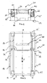
- the accumulator device for electronic components of the present invention comprises a container body 12 of substantially parallelepiped shape and closed on five out of the six faces for substantially forming a "box"; said container body 12 is made of a metal or other suitable type of material and is obtained, for example, through a moulding operation by drawing, bending-welding or other known type.
- Expansions or lips 14 and 14' are defined along each of the edges of the open front side or face of the container body 12, preferably extending by the entire length of the corresponding edges and exhibiting a plurality of holes or slots 15 the function whereof shall be explained hereinafter; in an alternative embodiment such expansions or lips 14 and 14' may be formed on the corresponding edges in a discontinuous manner.
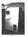
- a shaped plate or tray 16 is arranged inside the container body 12, suitable for receiving one or more reels 18 of electronic components picked up from the store, as schematised at figures 1, 2 and 4 .
- Said plate or tray 16, which is made of metal sheet or other suitable material, is arranged according to a direction substantially parallel to the support surface of the store and can slide according to the vertical direction indicated with the arrow Y in figure 2 .
- the sliding of the tray 16 is actuated by at least two belts 20 and, preferably of the toothed type, arranged inside or outside the container body 12, nearby and parallel to the inner surface of the side faces 12'.
- Said belts are each wound on at least two toothed wheels or pinions 22 connected by a shaft 24 and placed in rotation by a conventional motor 26, of the stepping or torque type or other known type, arranged outside or inside the container body as schematised in figure 3 .
- the motion transmission from the motor 26 to the toothed wheels or pinions 22 takes place, in the preferred embodiment at the figures, in a traditional manner using a belt-pinion system defined by a further belt 28 wound on a first further pinion 30 and on a second further pinion 32; both the further belt 28 and the first further pinion 30 and the second further pinion 32 are arranged outside the container body 12, with the second further pinion 32 fixed coaxially to the shaft 24 of connection between the toothed wheels or pinions 22.
- Two or more opposite plates 34 are formed or applied along the side edges of the tray 16 fixed to the belts 20 and the ends whereof are slidingly arranged relative to at least two vertical guides 36, fixed to the inner surface of the side faces 12' of the container body 12.
- Said guides 36 have the function of allowing the correct sliding of the tray 16 along the direction Y.
- the motor 26 may be fixed directly to the shaft 24 that places in rotation the toothed wheels or pinions 22.
- the movement of the tray 16 according to the direction Y can be actuated using a device of the pinion-rack type, worm screw or electrical actuators.
- the back side or face 12" opposite the open front side or face of the container body 12 exhibits, basically at the centre-top end of the back front 12" itself and centred relative to the greater median line M-M of the container body 12, an opening or slit 38 the horizontal dimension whereof and the height whereof are such as to allow the passage of a reel 18 of electronic components according to the ways described hereinafter.
- Two shoulders 40 are arranged on the same back side or face 12" of the container body 12, at the opening 38 and adjacent the smaller sides of the same, suitable for defining a guide for the reels 18 according to the ways that shall be detailed hereinafter; said shoulders 40 are fixed to the back front 12" of the container body 12 in a known manner, for example by screws, gluing or the like.
- the device 10 of the invention is arranged with the expansions or lips 14 and 14' of the open face of the container body 12 in contact with the inner surface of the store 42 of reels 18 of electronic components and nearby its bottom zone thereof; said device 10 is fixed to the store 42 in a known manner, for example by screws or other known types of retaining means.
- the open face of the container body 12 of the device of the invention is in case closed by a door (not shown in the figure).
- such device 10 of the invention is fixed on the outside of the store 42.
- the fixing position of such device relative to the store 42 may be at any height.
- a software program is associated the device 10 of the invention which has the function of controlling and managing the operation of the device itself and at the same time that of the store 42.
- a mechanical hand or actuator inside the store 42 and preferably of the pick & place type, receives the command via software and moves towards the cell of the store containing the reel matching the selected code, identifies it through a code reader (for example on the reels there are bar codes that contain all the information relating to the reel), picks it up from the cell and places it on the tray 16 of the accumulator device 10 introducing it through the slit or opening 38.
- the tray 16 Once the tray 16 has received a reel, it lowers by a quantity equal to the height of the reel itself and is thus ready for receiving a subsequent reel; for every new reel received the tray 16 lowers by a quantity equal to the height of the reel itself and this lowering continues until all the reels requested by the operator have been arranged on the tray.
- the accumulator device is provided with a conventional position sensor, for example a photocell, which detects the condition of reel placed on the tray 16 and enables the mechanical hand to pick up another reel.
- the tray 16 which moves to the height of the slit 38 to allow the gripper of the mechanical hand of the store 42 to pick up the reel and place it in the cell of the store matching its code.
- the tray 16 raises by a quantity equal to the height of the reel so as to move the next reel at the height of the slit 38 and allow the pick up thereof by the hand. This operation continues until all the reels on the tray 16 have been picked up from the tray and replaced into the store cells.
- the accumulator device for electronic components of the present invention advantageously allows to provide the operator with multiple reels of electronic components at the same time.
- a further advantage is the fact that since the device of the invention allows the operator not to have to pick up and replace one reel at a time on the accumulator, it allows drastically reducing the time for picking up and replacing the reels into the store and moreover it allows the operator to carry out other operations in "masked" time, that is, while the reel loading/unloading operation is in progress; moreover, this allows reducing the production times.
- a further advantage of the device of the invention is represented by the fact that during the step of replacement of the reels into the store, the operator can place multiple reels on the tray and even according to an order other than that by which they had been picked up from the store; a code reader will provide for the identification of the reel position in the suitable store cell and will send the information to the control system suitable for allowing the movement of the mechanical hand at said cell. Moreover, this allows reducing the mistakes that may be made by the operator.
Landscapes
- Engineering & Computer Science (AREA)
- Manufacturing & Machinery (AREA)
- Microelectronics & Electronic Packaging (AREA)
- Supply Devices, Intensifiers, Converters, And Telemotors (AREA)
- Reduction Or Emphasis Of Bandwidth Of Signals (AREA)
- Supply And Installment Of Electrical Components (AREA)
- Packaging Frangible Articles (AREA)
- Storage Of Web-Like Or Filamentary Materials (AREA)
- Secondary Cells (AREA)
Claims (15)
- Un dispositif accumulateur (10) pour des bobines de composants électroniques, particulièrement adapté pour être utilisé dans des magasins automatiques ou semi-automatiques pour stocker des composants électroniques, en particulier des bobines ou des rouleaux de composants CMS (Composants montés en surface) lequel comprend :- un conteneur (12) substantiellement en forme de parallélépipède ;- une plaque profilée ou un plateau (16), positionné à l'intérieur dudit corps conteneur (12) et capable de recevoir une ou plusieurs desdites bobines (18) de composants électroniques prélevées d'un magasin (42) associé audit corps container (12) ;- des dispositifs pour des mouvements contrôlés dudit plateau (16) le long d'un axe vertical à l'intérieur du corps conteneur et permettant le chargement et déchargement d'une ou plusieurs bobines de composants électroniques dans ledit plateau ;
ledit dispositif accumulateur se caractérisant par le fait que- ledit corps conteneur (12) / (15) est fermé sur cinq des six côtés et présente la partie arrière (12") à l'opposé de la partie frontale ouverte dudit corps du container (12) laquelle délimite à son extrémité centrale supérieure et centrée par rapport à l'axe médian majeur dudit corps container (12), une ouverture (38) apte à permettre le passage d'une bobine (18), et par le fait que
il comprend des dispositifs pour baisser ledit plateau (16) d'une course égale à l'hauteur de la bobine chargée lorsque une ultérieure bobine est chargée empilée sur la précédente, et pour soulever ledit plateau (16) d'une course égale à l'hauteur de la bobine chargée de la sorte à positionner la bobine empilée suivante à hauteur de ladite ouverture (38). - Le dispositif accumulateur conformément à la revendication 1, se caractérise par le fait que ledit dispositif de contrôle du mouvement vertical du plateau se compose de deux ou plus courroies (20) chacune enroulée sur au moins deux roues crantées ou pignons (22), reliés par un arbre (24) et mis en rotation par un moteur (26), et par au moins deux guides (36) qui permettent un glissement correct et précis par rapport à l'axe vertical (Y).
- Le dispositif accumulateur conformément à la revendication 2, se caractérise par le fait que lesdites corroies (20) sont crantées, positionnées à l'intérieur du corps du container (12) à proximité et parallèles à la surface intérieure des faces latérales (12') du corps conteneur même.
- Le dispositif accumulateur conformément à la revendication 2 ou 3, se caractérisant par le fait que ledit moteur (26) est un moteur pas à pas.
- Le dispositif accumulateur conformément à les revendications 2 ou 3, se caractérisant par le fait que ledit moteur (26) est un moteur couple.
- Le dispositif accumulateur conformément à la revendication 2, se caractérisant par le fait que la transmission du mouvement à partir de ce moteur (26) auxdites roues crantées ou pignons (22) utilise un système corroie-pignon qui inclue par la suite une corroie (28) enroulée sur un premier pignon additionnel (30) et un deuxième pignon additionnel (32), ce dernier étant fixé coaxial audit arbre (24).
- Le dispositif accumulateur conformément à la revendication 6, se caractérisant par le fait que ledit moteur (26) est directement relié à l'arbre (24) qui actionne lesdits roues crantées et pignons de transmission (22).
- Le dispositif accumulateur conformément à chacune des revendications de 1 à 7, se caractérisant par le fait que le mouvement dudit plateau (16) selon la direction (Y) est commandé par un dispositif de type pignon-crémaillère.
- Le dispositif accumulateur conformément à chacune des revendications de 1 à 7, se caractérisant par le fait que le mouvement dudit plateau (16) selon la direction (Y) est commandé par une vis.
- Le dispositif accumulateur conformément à chacune des revendications de 1 à 7, se caractérisant par le fait que le mouvement dudit plateau (16) selon la direction (Y) est obtenu en utilisant un ou plusieurs actuateurs électriques.
- Le dispositif accumulateur conformément à la revendication 2, se caractérisant par le fait que deux ou plus plaques opposées (34) sont constitués le long des bords latéraux dudit plateau 6) fixé à ladite / auxdites corroie(s) (20), et que les extrémités desdites plaques (34) sont conçues de manière à pouvoir les faire glisser par rapport à deux ou plus guides (36) fixés sur la surface interne des faces latérales (12') du corps du conteneur (12).
- Le dispositif accumulateur conformément aux précédentes revendications, caractérisé par le fait que deux épaulements (40) profilées et aptes à former un guide pour les bobines (18) sont disposées à proximité de ladite ouverture (38) et adjacentes aux côtés plus court de cette dernière.
- Le dispositif accumulateur conformément à chacune des précédentes revendications, caractérisé par le fait que le côté ouvert dudit corps conteneur (12) est fermé par une porte.
- Le dispositif accumulateur conformément à chacune des précédentes revendications de 1 à 13, se caractérisant par le fait qu'il est fixé à l'intérieur dudit magasin (42).
- Le dispositif accumulateur conformément à chacune des précédentes revendications de 1 à 13, se caractérisant par le fait qu'il est fixé à l'extérieur dudit magasin (42).
Applications Claiming Priority (1)
| Application Number | Priority Date | Filing Date | Title |
|---|---|---|---|
| IT002296A ITMI20062296A1 (it) | 2006-11-29 | 2006-11-29 | Dispositivo accumulatore per componenti elettronici |
Publications (3)
| Publication Number | Publication Date |
|---|---|
| EP1928221A2 EP1928221A2 (fr) | 2008-06-04 |
| EP1928221A3 EP1928221A3 (fr) | 2010-02-17 |
| EP1928221B1 true EP1928221B1 (fr) | 2011-05-04 |
Family
ID=39265225
Family Applications (1)
| Application Number | Title | Priority Date | Filing Date |
|---|---|---|---|
| EP07020356A Active EP1928221B1 (fr) | 2006-11-29 | 2007-10-18 | Dispositif accumulateur pour composants électroniques |
Country Status (5)
| Country | Link |
|---|---|
| EP (1) | EP1928221B1 (fr) |
| AT (1) | ATE508624T1 (fr) |
| DE (1) | DE602007014306D1 (fr) |
| ES (1) | ES2365937T3 (fr) |
| IT (1) | ITMI20062296A1 (fr) |
Cited By (1)
| Publication number | Priority date | Publication date | Assignee | Title |
|---|---|---|---|---|
| RU2667505C1 (ru) * | 2014-12-22 | 2018-09-21 | Эсседжи Систем Сёрвис С.Р.Л. | Усовершенствованный модуль для хранения |
Families Citing this family (3)
| Publication number | Priority date | Publication date | Assignee | Title |
|---|---|---|---|---|
| CN108200759B (zh) * | 2012-03-12 | 2020-04-28 | 麦克罗尼克迈达塔有限责任公司 | 用于部件的自动存储设备 |
| WO2015040085A1 (fr) | 2013-09-18 | 2015-03-26 | Mycronic AB | Procédé, système et dispositif pour identifier un bac dans un système smt |
| EP4049944A4 (fr) * | 2019-10-25 | 2022-11-09 | Fuji Corporation | Récipient de stockage |
Family Cites Families (4)
| Publication number | Priority date | Publication date | Assignee | Title |
|---|---|---|---|---|
| EP0302542B1 (fr) * | 1987-07-14 | 1994-01-26 | Koninklijke Philips Electronics N.V. | Dispositif pour transporter des supports à partir et en direction d'un dispositif de positionnement et dispositif sélecteur destiné à un dispositif |
| JPH066084A (ja) * | 1992-06-19 | 1994-01-14 | Olympus Optical Co Ltd | 電子部品自動実装機 |
| US6662966B2 (en) * | 2001-06-28 | 2003-12-16 | Smtc Corporation | Surface mount manufacturing storage system |
| JP2005347352A (ja) * | 2004-05-31 | 2005-12-15 | Yamaha Motor Co Ltd | フィーダ交換台車およびそれを備えた実装機 |
-
2006
- 2006-11-29 IT IT002296A patent/ITMI20062296A1/it unknown
-
2007
- 2007-10-18 EP EP07020356A patent/EP1928221B1/fr active Active
- 2007-10-18 DE DE602007014306T patent/DE602007014306D1/de active Active
- 2007-10-18 ES ES07020356T patent/ES2365937T3/es active Active
- 2007-10-18 AT AT07020356T patent/ATE508624T1/de not_active IP Right Cessation
Cited By (1)
| Publication number | Priority date | Publication date | Assignee | Title |
|---|---|---|---|---|
| RU2667505C1 (ru) * | 2014-12-22 | 2018-09-21 | Эсседжи Систем Сёрвис С.Р.Л. | Усовершенствованный модуль для хранения |
Also Published As
| Publication number | Publication date |
|---|---|
| DE602007014306D1 (de) | 2011-06-16 |
| EP1928221A2 (fr) | 2008-06-04 |
| EP1928221A3 (fr) | 2010-02-17 |
| ATE508624T1 (de) | 2011-05-15 |
| ITMI20062296A1 (it) | 2008-05-30 |
| ES2365937T3 (es) | 2011-10-13 |
Similar Documents
| Publication | Publication Date | Title |
|---|---|---|
| EP1928221B1 (fr) | Dispositif accumulateur pour composants électroniques | |
| CN1176445C (zh) | 钞票整检设备 | |
| US4734005A (en) | Vending machine for video cassettes | |
| US4563120A (en) | Device for storing and/or retrieving objects | |
| JPH066084A (ja) | 電子部品自動実装機 | |
| DE102023109756A1 (de) | Bauteilversorgungsvorrichtung | |
| EP3031037B1 (fr) | Entrepôt automatique | |
| JP2011060816A (ja) | 電子部品供給装置および電子部品供給方法 | |
| EP0995706A1 (fr) | Changeur de bobines | |
| CN111056329A (zh) | 供料机构 | |
| JP5561718B2 (ja) | パレット入替システム | |
| US20220055834A1 (en) | A storage unit for smt supplies | |
| US8265785B2 (en) | External load port magazine and storage system and method of using same | |
| DE69525788T2 (de) | Plattenwiedergabegerät mit Plattenwechselfunktion | |
| US8898683B2 (en) | Disc drive unit and apparatus having the same | |
| KR101427084B1 (ko) | 트레이 피더 | |
| CN112690571A (zh) | 储料系统 | |
| CN208560513U (zh) | 一种基于物联网的智能仓库 | |
| DE3904726C2 (fr) | ||
| US12583228B2 (en) | Storage system and printing system | |
| DE60319054T2 (de) | Einrichtung zur Montage von elektronischen Bauteilen | |
| EP0924144B1 (fr) | Magasin à rayonnage | |
| KR100603029B1 (ko) | 논스톱방식의 트레이 공급장치 | |
| CN219947306U (zh) | 一种料仓机构及热熔机 | |
| CN208560514U (zh) | 一种用于智能仓库的存放结构 |
Legal Events
| Date | Code | Title | Description |
|---|---|---|---|
| PUAI | Public reference made under article 153(3) epc to a published international application that has entered the european phase |
Free format text: ORIGINAL CODE: 0009012 |
|
| AK | Designated contracting states |
Kind code of ref document: A2 Designated state(s): AT BE BG CH CY CZ DE DK EE ES FI FR GB GR HU IE IS IT LI LT LU LV MC MT NL PL PT RO SE SI SK TR |
|
| AX | Request for extension of the european patent |
Extension state: AL BA HR MK RS |
|
| PUAL | Search report despatched |
Free format text: ORIGINAL CODE: 0009013 |
|
| AK | Designated contracting states |
Kind code of ref document: A3 Designated state(s): AT BE BG CH CY CZ DE DK EE ES FI FR GB GR HU IE IS IT LI LT LU LV MC MT NL PL PT RO SE SI SK TR |
|
| AX | Request for extension of the european patent |
Extension state: AL BA HR MK RS |
|
| 17P | Request for examination filed |
Effective date: 20100818 |
|
| AKX | Designation fees paid |
Designated state(s): AT BE BG CH CY CZ DE DK EE ES FI FR GB GR HU IE IS IT LI LT LU LV MC MT NL PL PT RO SE SI SK TR |
|
| RIC1 | Information provided on ipc code assigned before grant |
Ipc: H05K 13/00 20060101AFI20100922BHEP |
|
| D17P | Request for examination filed (deleted) | ||
| GRAP | Despatch of communication of intention to grant a patent |
Free format text: ORIGINAL CODE: EPIDOSNIGR1 |
|
| R17P | Request for examination filed (corrected) |
Effective date: 20100818 |
|
| GRAS | Grant fee paid |
Free format text: ORIGINAL CODE: EPIDOSNIGR3 |
|
| GRAA | (expected) grant |
Free format text: ORIGINAL CODE: 0009210 |
|
| AK | Designated contracting states |
Kind code of ref document: B1 Designated state(s): AT BE BG CH CY CZ DE DK EE ES FI FR GB GR HU IE IS IT LI LT LU LV MC MT NL PL PT RO SE SI SK TR |
|
| REG | Reference to a national code |
Ref country code: GB Ref legal event code: FG4D |
|
| REG | Reference to a national code |
Ref country code: CH Ref legal event code: EP |
|
| REG | Reference to a national code |
Ref country code: IE Ref legal event code: FG4D |
|
| REF | Corresponds to: |
Ref document number: 602007014306 Country of ref document: DE Date of ref document: 20110616 Kind code of ref document: P |
|
| REG | Reference to a national code |
Ref country code: DE Ref legal event code: R096 Ref document number: 602007014306 Country of ref document: DE Effective date: 20110616 |
|
| REG | Reference to a national code |
Ref country code: CH Ref legal event code: PFA Owner name: ESSEGI SYSTEM SERVICE S.R.L. Free format text: ESSEGI SYSTEM SERVICE S.R.L.#VIA DEL COMMERCIO 39#36050 SOVIZZO (VI) (IT) -TRANSFER TO- ESSEGI SYSTEM SERVICE S.R.L.#VIA ZAMBON 14/16#36051 CREAZZO (VI) (IT) Ref country code: CH Ref legal event code: NV Representative=s name: ZIMMERLI, WAGNER & PARTNER AG |
|
| REG | Reference to a national code |
Ref country code: NL Ref legal event code: VDEP Effective date: 20110504 |
|
| REG | Reference to a national code |
Ref country code: ES Ref legal event code: FG2A Ref document number: 2365937 Country of ref document: ES Kind code of ref document: T3 Effective date: 20111013 |
|
| PG25 | Lapsed in a contracting state [announced via postgrant information from national office to epo] |
Ref country code: PT Free format text: LAPSE BECAUSE OF FAILURE TO SUBMIT A TRANSLATION OF THE DESCRIPTION OR TO PAY THE FEE WITHIN THE PRESCRIBED TIME-LIMIT Effective date: 20110905 Ref country code: SE Free format text: LAPSE BECAUSE OF FAILURE TO SUBMIT A TRANSLATION OF THE DESCRIPTION OR TO PAY THE FEE WITHIN THE PRESCRIBED TIME-LIMIT Effective date: 20110504 Ref country code: LT Free format text: LAPSE BECAUSE OF FAILURE TO SUBMIT A TRANSLATION OF THE DESCRIPTION OR TO PAY THE FEE WITHIN THE PRESCRIBED TIME-LIMIT Effective date: 20110504 |
|
| PG25 | Lapsed in a contracting state [announced via postgrant information from national office to epo] |
Ref country code: CY Free format text: LAPSE BECAUSE OF FAILURE TO SUBMIT A TRANSLATION OF THE DESCRIPTION OR TO PAY THE FEE WITHIN THE PRESCRIBED TIME-LIMIT Effective date: 20110504 Ref country code: GR Free format text: LAPSE BECAUSE OF FAILURE TO SUBMIT A TRANSLATION OF THE DESCRIPTION OR TO PAY THE FEE WITHIN THE PRESCRIBED TIME-LIMIT Effective date: 20110805 Ref country code: AT Free format text: LAPSE BECAUSE OF FAILURE TO SUBMIT A TRANSLATION OF THE DESCRIPTION OR TO PAY THE FEE WITHIN THE PRESCRIBED TIME-LIMIT Effective date: 20110504 Ref country code: FI Free format text: LAPSE BECAUSE OF FAILURE TO SUBMIT A TRANSLATION OF THE DESCRIPTION OR TO PAY THE FEE WITHIN THE PRESCRIBED TIME-LIMIT Effective date: 20110504 Ref country code: LV Free format text: LAPSE BECAUSE OF FAILURE TO SUBMIT A TRANSLATION OF THE DESCRIPTION OR TO PAY THE FEE WITHIN THE PRESCRIBED TIME-LIMIT Effective date: 20110504 Ref country code: BE Free format text: LAPSE BECAUSE OF FAILURE TO SUBMIT A TRANSLATION OF THE DESCRIPTION OR TO PAY THE FEE WITHIN THE PRESCRIBED TIME-LIMIT Effective date: 20110504 Ref country code: SI Free format text: LAPSE BECAUSE OF FAILURE TO SUBMIT A TRANSLATION OF THE DESCRIPTION OR TO PAY THE FEE WITHIN THE PRESCRIBED TIME-LIMIT Effective date: 20110504 Ref country code: IS Free format text: LAPSE BECAUSE OF FAILURE TO SUBMIT A TRANSLATION OF THE DESCRIPTION OR TO PAY THE FEE WITHIN THE PRESCRIBED TIME-LIMIT Effective date: 20110904 |
|
| PG25 | Lapsed in a contracting state [announced via postgrant information from national office to epo] |
Ref country code: NL Free format text: LAPSE BECAUSE OF FAILURE TO SUBMIT A TRANSLATION OF THE DESCRIPTION OR TO PAY THE FEE WITHIN THE PRESCRIBED TIME-LIMIT Effective date: 20110504 |
|
| PG25 | Lapsed in a contracting state [announced via postgrant information from national office to epo] |
Ref country code: EE Free format text: LAPSE BECAUSE OF FAILURE TO SUBMIT A TRANSLATION OF THE DESCRIPTION OR TO PAY THE FEE WITHIN THE PRESCRIBED TIME-LIMIT Effective date: 20110504 Ref country code: CZ Free format text: LAPSE BECAUSE OF FAILURE TO SUBMIT A TRANSLATION OF THE DESCRIPTION OR TO PAY THE FEE WITHIN THE PRESCRIBED TIME-LIMIT Effective date: 20110504 |
|
| PG25 | Lapsed in a contracting state [announced via postgrant information from national office to epo] |
Ref country code: SK Free format text: LAPSE BECAUSE OF FAILURE TO SUBMIT A TRANSLATION OF THE DESCRIPTION OR TO PAY THE FEE WITHIN THE PRESCRIBED TIME-LIMIT Effective date: 20110504 Ref country code: DK Free format text: LAPSE BECAUSE OF FAILURE TO SUBMIT A TRANSLATION OF THE DESCRIPTION OR TO PAY THE FEE WITHIN THE PRESCRIBED TIME-LIMIT Effective date: 20110504 Ref country code: PL Free format text: LAPSE BECAUSE OF FAILURE TO SUBMIT A TRANSLATION OF THE DESCRIPTION OR TO PAY THE FEE WITHIN THE PRESCRIBED TIME-LIMIT Effective date: 20110504 Ref country code: RO Free format text: LAPSE BECAUSE OF FAILURE TO SUBMIT A TRANSLATION OF THE DESCRIPTION OR TO PAY THE FEE WITHIN THE PRESCRIBED TIME-LIMIT Effective date: 20110504 |
|
| PLBE | No opposition filed within time limit |
Free format text: ORIGINAL CODE: 0009261 |
|
| STAA | Information on the status of an ep patent application or granted ep patent |
Free format text: STATUS: NO OPPOSITION FILED WITHIN TIME LIMIT |
|
| 26N | No opposition filed |
Effective date: 20120207 |
|
| PG25 | Lapsed in a contracting state [announced via postgrant information from national office to epo] |
Ref country code: IT Free format text: LAPSE BECAUSE OF FAILURE TO SUBMIT A TRANSLATION OF THE DESCRIPTION OR TO PAY THE FEE WITHIN THE PRESCRIBED TIME-LIMIT Effective date: 20110504 Ref country code: MC Free format text: LAPSE BECAUSE OF NON-PAYMENT OF DUE FEES Effective date: 20111031 |
|
| REG | Reference to a national code |
Ref country code: DE Ref legal event code: R097 Ref document number: 602007014306 Country of ref document: DE Effective date: 20120207 |
|
| REG | Reference to a national code |
Ref country code: IE Ref legal event code: MM4A |
|
| PG25 | Lapsed in a contracting state [announced via postgrant information from national office to epo] |
Ref country code: IE Free format text: LAPSE BECAUSE OF NON-PAYMENT OF DUE FEES Effective date: 20111018 |
|
| PG25 | Lapsed in a contracting state [announced via postgrant information from national office to epo] |
Ref country code: MT Free format text: LAPSE BECAUSE OF FAILURE TO SUBMIT A TRANSLATION OF THE DESCRIPTION OR TO PAY THE FEE WITHIN THE PRESCRIBED TIME-LIMIT Effective date: 20110504 |
|
| PG25 | Lapsed in a contracting state [announced via postgrant information from national office to epo] |
Ref country code: LU Free format text: LAPSE BECAUSE OF NON-PAYMENT OF DUE FEES Effective date: 20111018 |
|
| PG25 | Lapsed in a contracting state [announced via postgrant information from national office to epo] |
Ref country code: BG Free format text: LAPSE BECAUSE OF FAILURE TO SUBMIT A TRANSLATION OF THE DESCRIPTION OR TO PAY THE FEE WITHIN THE PRESCRIBED TIME-LIMIT Effective date: 20110804 |
|
| PG25 | Lapsed in a contracting state [announced via postgrant information from national office to epo] |
Ref country code: TR Free format text: LAPSE BECAUSE OF FAILURE TO SUBMIT A TRANSLATION OF THE DESCRIPTION OR TO PAY THE FEE WITHIN THE PRESCRIBED TIME-LIMIT Effective date: 20110504 |
|
| PG25 | Lapsed in a contracting state [announced via postgrant information from national office to epo] |
Ref country code: HU Free format text: LAPSE BECAUSE OF FAILURE TO SUBMIT A TRANSLATION OF THE DESCRIPTION OR TO PAY THE FEE WITHIN THE PRESCRIBED TIME-LIMIT Effective date: 20110504 |
|
| REG | Reference to a national code |
Ref country code: CH Ref legal event code: NV Representative=s name: WAGNER PATENT AG, CH |
|
| REG | Reference to a national code |
Ref country code: FR Ref legal event code: PLFP Year of fee payment: 9 |
|
| REG | Reference to a national code |
Ref country code: FR Ref legal event code: PLFP Year of fee payment: 10 |
|
| REG | Reference to a national code |
Ref country code: FR Ref legal event code: PLFP Year of fee payment: 11 |
|
| REG | Reference to a national code |
Ref country code: CH Ref legal event code: NV Representative=s name: ORITI PATENTS - FRANCO ORITI, CH |
|
| REG | Reference to a national code |
Ref country code: FR Ref legal event code: PLFP Year of fee payment: 12 |
|
| REG | Reference to a national code |
Ref country code: DE Ref legal event code: R082 Ref document number: 602007014306 Country of ref document: DE Representative=s name: K & H BONAPAT PATENTANWAELTE KOCH VON BEHREN &, DE Ref country code: DE Ref legal event code: R081 Ref document number: 602007014306 Country of ref document: DE Owner name: ESSEGI AUTOMATION S.R.L., IT Free format text: FORMER OWNER: ESSEGI SYSTEM SERVICE S.R.L., SOVIZZO, (VI), IT |
|
| REG | Reference to a national code |
Ref country code: CH Ref legal event code: PUE Owner name: ESSEGI AUTOMATION S.R.L., IT Free format text: FORMER OWNER: ESSEGI SYSTEM SERVICE S.R.L., IT |
|
| REG | Reference to a national code |
Ref country code: ES Ref legal event code: PC2A Owner name: ESSEGI AUTOMATION S.R.L. Effective date: 20190924 |
|
| P01 | Opt-out of the competence of the unified patent court (upc) registered |
Effective date: 20230530 |
|
| REG | Reference to a national code |
Ref country code: CH Ref legal event code: U11 Free format text: ST27 STATUS EVENT CODE: U-0-0-U10-U11 (AS PROVIDED BY THE NATIONAL OFFICE) Effective date: 20251101 |
|
| PGFP | Annual fee paid to national office [announced via postgrant information from national office to epo] |
Ref country code: DE Payment date: 20251021 Year of fee payment: 19 |
|
| PGFP | Annual fee paid to national office [announced via postgrant information from national office to epo] |
Ref country code: GB Payment date: 20251022 Year of fee payment: 19 |
|
| PGFP | Annual fee paid to national office [announced via postgrant information from national office to epo] |
Ref country code: FR Payment date: 20251029 Year of fee payment: 19 |
|
| PGFP | Annual fee paid to national office [announced via postgrant information from national office to epo] |
Ref country code: CH Payment date: 20251101 Year of fee payment: 19 |
|
| PGFP | Annual fee paid to national office [announced via postgrant information from national office to epo] |
Ref country code: ES Payment date: 20251210 Year of fee payment: 19 |