EP1928574B1 - Separateur pour fluides, notamment pour condensats, a base de gaz comprimes charges de liquides - Google Patents
Separateur pour fluides, notamment pour condensats, a base de gaz comprimes charges de liquides Download PDFInfo
- Publication number
- EP1928574B1 EP1928574B1 EP06806879A EP06806879A EP1928574B1 EP 1928574 B1 EP1928574 B1 EP 1928574B1 EP 06806879 A EP06806879 A EP 06806879A EP 06806879 A EP06806879 A EP 06806879A EP 1928574 B1 EP1928574 B1 EP 1928574B1
- Authority
- EP
- European Patent Office
- Prior art keywords
- separator
- housing
- hollow cylinder
- condensate
- separator element
- Prior art date
- Legal status (The legal status is an assumption and is not a legal conclusion. Google has not performed a legal analysis and makes no representation as to the accuracy of the status listed.)
- Not-in-force
Links
- 239000007789 gas Substances 0.000 title claims abstract description 49
- 239000007788 liquid Substances 0.000 title abstract description 16
- 239000012530 fluid Substances 0.000 claims 2
- 238000000926 separation method Methods 0.000 abstract description 13
- 238000001179 sorption measurement Methods 0.000 abstract description 3
- 238000011045 prefiltration Methods 0.000 description 13
- 239000000463 material Substances 0.000 description 5
- 230000008021 deposition Effects 0.000 description 3
- 238000000465 moulding Methods 0.000 description 3
- 238000005057 refrigeration Methods 0.000 description 2
- 239000000654 additive Substances 0.000 description 1
- 230000004323 axial length Effects 0.000 description 1
- 239000004744 fabric Substances 0.000 description 1
- 230000002349 favourable effect Effects 0.000 description 1
- 239000012535 impurity Substances 0.000 description 1
- 239000002245 particle Substances 0.000 description 1
- 239000011148 porous material Substances 0.000 description 1
- 239000012716 precipitator Substances 0.000 description 1
- 239000007787 solid Substances 0.000 description 1
- XLYOFNOQVPJJNP-UHFFFAOYSA-N water Substances O XLYOFNOQVPJJNP-UHFFFAOYSA-N 0.000 description 1
Images


Classifications
-
- B—PERFORMING OPERATIONS; TRANSPORTING
- B01—PHYSICAL OR CHEMICAL PROCESSES OR APPARATUS IN GENERAL
- B01D—SEPARATION
- B01D50/00—Combinations of methods or devices for separating particles from gases or vapours
- B01D50/20—Combinations of devices covered by groups B01D45/00 and B01D46/00
-
- B—PERFORMING OPERATIONS; TRANSPORTING
- B01—PHYSICAL OR CHEMICAL PROCESSES OR APPARATUS IN GENERAL
- B01D—SEPARATION
- B01D45/00—Separating dispersed particles from gases or vapours by gravity, inertia, or centrifugal forces
- B01D45/04—Separating dispersed particles from gases or vapours by gravity, inertia, or centrifugal forces by utilising inertia
- B01D45/08—Separating dispersed particles from gases or vapours by gravity, inertia, or centrifugal forces by utilising inertia by impingement against baffle separators
-
- Y—GENERAL TAGGING OF NEW TECHNOLOGICAL DEVELOPMENTS; GENERAL TAGGING OF CROSS-SECTIONAL TECHNOLOGIES SPANNING OVER SEVERAL SECTIONS OF THE IPC; TECHNICAL SUBJECTS COVERED BY FORMER USPC CROSS-REFERENCE ART COLLECTIONS [XRACs] AND DIGESTS
- Y10—TECHNICAL SUBJECTS COVERED BY FORMER USPC
- Y10S—TECHNICAL SUBJECTS COVERED BY FORMER USPC CROSS-REFERENCE ART COLLECTIONS [XRACs] AND DIGESTS
- Y10S55/00—Gas separation
- Y10S55/05—Methods of making filter
-
- Y—GENERAL TAGGING OF NEW TECHNOLOGICAL DEVELOPMENTS; GENERAL TAGGING OF CROSS-SECTIONAL TECHNOLOGIES SPANNING OVER SEVERAL SECTIONS OF THE IPC; TECHNICAL SUBJECTS COVERED BY FORMER USPC CROSS-REFERENCE ART COLLECTIONS [XRACs] AND DIGESTS
- Y10—TECHNICAL SUBJECTS COVERED BY FORMER USPC
- Y10S—TECHNICAL SUBJECTS COVERED BY FORMER USPC CROSS-REFERENCE ART COLLECTIONS [XRACs] AND DIGESTS
- Y10S55/00—Gas separation
- Y10S55/12—Pocket type filter
-
- Y—GENERAL TAGGING OF NEW TECHNOLOGICAL DEVELOPMENTS; GENERAL TAGGING OF CROSS-SECTIONAL TECHNOLOGIES SPANNING OVER SEVERAL SECTIONS OF THE IPC; TECHNICAL SUBJECTS COVERED BY FORMER USPC CROSS-REFERENCE ART COLLECTIONS [XRACs] AND DIGESTS
- Y10—TECHNICAL SUBJECTS COVERED BY FORMER USPC
- Y10S—TECHNICAL SUBJECTS COVERED BY FORMER USPC CROSS-REFERENCE ART COLLECTIONS [XRACs] AND DIGESTS
- Y10S55/00—Gas separation
- Y10S55/14—Inertia separator
-
- Y—GENERAL TAGGING OF NEW TECHNOLOGICAL DEVELOPMENTS; GENERAL TAGGING OF CROSS-SECTIONAL TECHNOLOGIES SPANNING OVER SEVERAL SECTIONS OF THE IPC; TECHNICAL SUBJECTS COVERED BY FORMER USPC CROSS-REFERENCE ART COLLECTIONS [XRACs] AND DIGESTS
- Y10—TECHNICAL SUBJECTS COVERED BY FORMER USPC
- Y10S—TECHNICAL SUBJECTS COVERED BY FORMER USPC CROSS-REFERENCE ART COLLECTIONS [XRACs] AND DIGESTS
- Y10S55/00—Gas separation
- Y10S55/17—Compressed air water removal
-
- Y—GENERAL TAGGING OF NEW TECHNOLOGICAL DEVELOPMENTS; GENERAL TAGGING OF CROSS-SECTIONAL TECHNOLOGIES SPANNING OVER SEVERAL SECTIONS OF THE IPC; TECHNICAL SUBJECTS COVERED BY FORMER USPC CROSS-REFERENCE ART COLLECTIONS [XRACs] AND DIGESTS
- Y10—TECHNICAL SUBJECTS COVERED BY FORMER USPC
- Y10S—TECHNICAL SUBJECTS COVERED BY FORMER USPC CROSS-REFERENCE ART COLLECTIONS [XRACs] AND DIGESTS
- Y10S55/00—Gas separation
- Y10S55/37—Louvers
Definitions
- the invention relates to a separator for liquids, in particular condensate, from liquid-laden, compressed gases, wherein arranged in a cup-shaped housing with a arranged at the bottom of the housing collecting space for the separated liquid and a cover designed as a lid with a gas supply and a gas discharge head a separating element is.
- cyclone separators have the fundamental disadvantage that their efficiency depends substantially on the volume flow of the dehumidified gases.
- the same swirl inserts must be used for cyclone separators. The greater length can therefore not be exploited to increase the efficiency of the deposition.
- different sized swirl inserts must be used for different diameter housing.
- a liquid separator with a collecting space and a connection cover is known, which radially from inside to outside flowed through, concentrically arranged separating elements through which the gas stream is guided in a labyrinth manner.
- the US 5,112,375 discloses a liquid separator cartridge with separation louvers radially disposed about a cylindrical cavity.
- the invention has for its object to develop a separator for liquids, in particular condensate, from liquid-laden, compressed gases, which can be preceded by a pre-filter to protect the pre-filter equipped with a porous filter insert the compressed gas treatment plant from overloading by excessive amounts of condensate.
- the housing used should be used universally both as a pre-filter with a porous filter cartridge and as a separator for the liquid without major retooling.
- the separating element is designed as a closed down by a bottom cap hollow cylinder, which is arranged at a distance from the wall of the housing and connected at the top with an adapter cap to an outlet of the gas supply line in that the wall of the separating element has a plurality of flow baffles formed by baffles and baffles for the liquid-laden, compressed gases, through which the introduced from the gas supply via the adapter cap in the interior of the separating element, liquid laden, compressed gases are directed radially outwardly into the space between the wall of the housing and the separation element.
- the gases to be dehumidified are conducted from the inside to the outside.
- This means that this type of guidance of the volume flow is equal to the volume flow in a prefilter with porous material made of hollow cylindrical filter element. Therefore, the same housings can be used for the separator and the conventional porous filter element prefilter without requiring changes in gas supply and gas discharge.
- the volume flow is less critical than in a cyclone separator. Since the separation element is designed as a hollow cylinder, the separation element can be adapted to the length of the housing. This allows a problem-free consideration of different volume flows.
- the separator according to the invention is the combination with a conventional prefilter with a filter element made of porous Filter material.
- a conventional prefilter with a filter element made of porous Filter material.
- the hollow cylindrical separating element in an outer hollow cylindrical filter element made of porous filter material.
- the baffle and impact body are designed as profile strips and arranged spatially on different sized concentric cylinders.
- the inner and outer profile strips should be arranged on a gap.
- the flow guidance and efficiency of the deposition of condensate can be further improved by the fact that the inner and outer profile strips face each other and overlap each other. Is particularly favorable for the flow guidance, if the inner profile strips to the interior of the Abscheidianas and the outer profile strips to the outer space convex, angled or U-shaped profiled.
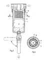
- the in Fig. 1 and 2 shown separator for moisture-laden, compressed gases has a cup-shaped, cylindrical housing 1 with a lower plenum 3 for separated from the gas liquid 4.
- a valve 7 In the bottom 5 of the housing 1 is an outlet 6 with a valve 7 is provided. About this outlet 6, the liquid 4 can be drained.
- the housing 1 is closed at the top by a screw-on head piece 8 designed as a lid.
- the head piece 8 has a gas feed line 9 with a central inlet nozzle 10 and a gas discharge line 11, which starts from an annular space 12 on the wall of the housing 1.
- the separation element 13 is formed as a hollow cylinder 14, which is closed at the bottom by a bottom cap 15 and above by an adapter cap 16 with a central opening 17 into which the inlet nozzle 10 opens.
- the cylindrical wall of the hollow cylinder 14 between the bottom cap 15 and the adapter cap 16 is not closed, but radially permeable.
- it has a plurality of flow baffles 18, 19, where moisture contained in the moisture-laden gases is deposited to a large extent when the gases introduced from the interior 20 of the hollow cylinder 14 in the outer annular space 12 between the hollow cylinder 14 and the wall of the Go housing 1. This moisture then drips down into the plenum 3 of the housing 1 and collects as in Fig. 1 is shown.
- the flow baffles 18, 19 are formed by profiled strips, which are geometrically arranged on different sized cylinders. With their ends they are held on the bottom cap 15 or the adapter cap 16. Each group of moldings is spaced apart. The profile strips of different groups are each arranged on a gap and overlap each other.
- the inner profile strips 18 are convex to the interior. They are designed primarily as a guide body, because they ensure that the dehumidified gases flow from the interior 20 to the outside against the outer profile strips 19. The air thus bounces on these profile strips 19, so that they act primarily as an impact body. From the profile strips 19, the gases are deflected and then redirected again by the inner profile strips 18 to finally reach the annular space 12. At each impact on the strips 18, 19, especially when hitting the outer moldings 19 moisture is deposited according to the impact principle, which, as in Fig. 1 shown drains off the profile strips 18, 19 and dripped down.
- Fig. 7 is different from that of FIGS. 5 and 6 only in the form of the inner and outer moldings.
- the embodiment of Fig. 8 differs from the other embodiments in that here is a combination of the outer strips 19 of the embodiment of FIGS. 5 and 6 and the inner profile strips of the embodiment of Fig. 7 is realized.
- FIGS. 3 and 4 is different from that of Figures 1 and 2 only in that the hollow cylinder 14 of the separation element 13 is seated in a hollow cylindrical filter element 21 made of porous filter material.
- the porous filter material can be designed to increase the surface as a pleated filter cloth.
Landscapes
- Chemical & Material Sciences (AREA)
- Chemical Kinetics & Catalysis (AREA)
- Filtering Of Dispersed Particles In Gases (AREA)
- Separating Particles In Gases By Inertia (AREA)
- Drying Of Gases (AREA)
- Gas Separation By Absorption (AREA)
Claims (4)
- Séparateur pour fluides, en particulier pour condensat à base de gaz comprimés chargés de liquide, dans lequel un élément séparateur (13) est disposé dans un carter (1) en forme de pot, avec une chambre collectrice (3), disposée au fond du carter (1) pour recueillir le fluide éliminé (4), et avec une pièce de tête (8), réalisée en forme de couvercle, avec une conduite d'amenée de gaz (9) et une conduite de dérivation de gaz (11), caractérisé en ce que l'élément séparateur (13) est réalisé sous la forme d'un cylindre creux (14), fermé, en bas, par une calotte de fond (15), lequel est disposé à distance de la paroi du carter (1) et est raccordé, en haut, par une calotte adaptatrice (16), à une sortie (10) de la conduite d'amenée de gaz (9), et en ce que la paroi du cylindre creux (14) de l'élément séparateur (13) présente de nombreuses barres profilées, qui, disposées, par rapport les unes aux autres et parallèlement à l'axe du cylindre creux, sur des surfaces du cylindre concentriques, de différentes grandeurs, et sur des intervalles, forment, en tant que corps de guidage et de déflexion, des chicanes (18, 19) pour l'écoulement des gaz comprimés, chargés de liquide, qui, en provenance de la conduite d'amenée de gaz (9), sont introduits dans l'espace intérieur (20) de l'élément séparateur (13), par l'intermédiaire de la calotte adaptatrice (16), et qui, de là, sont conduits, par l'intermédiaire des chicanes d'écoulement (18, 19), en direction radiale, vers l'extérieur, dans l'espace intermédiaire (12) entre la paroi du carter (1) et l'élément séparateur (13).
- Séparateur selon la revendication 1, caractérisé en ce que les barres profilées intérieures et extérieures sont orientées les unes vers les autres et se chevauchent.
- Séparateur selon revendication 2 ou 3, caractérisé en ce que les barres profilées intérieures, en direction de l'espace intérieur (20) de l'élément séparateur (13), et les barres profilées extérieures, en direction de l'espace intermédiaire extérieur (12), présentent des profils convexes, en cornière ou en forme de U.
- Séparateur selon l'une des revendications 1 à 3, caractérisé en ce que l'élément séparateur (13) est logé dans un élément filtrant (21) extérieur, en forme de cylindre creux.
Applications Claiming Priority (2)
| Application Number | Priority Date | Filing Date | Title |
|---|---|---|---|
| DE102005046810A DE102005046810B4 (de) | 2005-09-30 | 2005-09-30 | Abscheider für Flüssigkeiten, insbesondere Kondensat, aus flüssigkeitsbeladenen, komprimierten Gasen |
| PCT/EP2006/066865 WO2007036560A1 (fr) | 2005-09-30 | 2006-09-28 | Separateur pour fluides, notamment pour condensats, a base de gaz comprimes charges de liquides |
Publications (2)
| Publication Number | Publication Date |
|---|---|
| EP1928574A1 EP1928574A1 (fr) | 2008-06-11 |
| EP1928574B1 true EP1928574B1 (fr) | 2010-01-06 |
Family
ID=37450738
Family Applications (1)
| Application Number | Title | Priority Date | Filing Date |
|---|---|---|---|
| EP06806879A Not-in-force EP1928574B1 (fr) | 2005-09-30 | 2006-09-28 | Separateur pour fluides, notamment pour condensats, a base de gaz comprimes charges de liquides |
Country Status (5)
| Country | Link |
|---|---|
| US (1) | US8097051B2 (fr) |
| EP (1) | EP1928574B1 (fr) |
| AT (1) | ATE454201T1 (fr) |
| DE (3) | DE102005046810B4 (fr) |
| WO (1) | WO2007036560A1 (fr) |
Families Citing this family (17)
| Publication number | Priority date | Publication date | Assignee | Title |
|---|---|---|---|---|
| CN101890265B (zh) * | 2010-01-26 | 2012-08-15 | 南通宝钢钢铁有限公司 | 一种气液油水分离器 |
| EP2621605A1 (fr) | 2010-09-30 | 2013-08-07 | Sulzer Chemtech AG | Séparateur de gouttelettes |
| CN106194662B (zh) | 2012-02-27 | 2020-03-13 | 纳博特斯克汽车零部件有限公司 | 油分离器 |
| EP2821605B1 (fr) | 2012-02-27 | 2022-01-12 | Nabtesco Automotive Corporation | Séparateur d'huile |
| CN104271949B (zh) | 2012-02-27 | 2016-08-24 | 纳薄特斯克汽车零部件有限公司 | 分油器 |
| CN105688518A (zh) | 2012-05-10 | 2016-06-22 | 纳薄特斯克汽车零部件有限公司 | 油分离器 |
| IN2014MN02671A (fr) | 2012-07-02 | 2015-08-28 | Nabtesco Automotive Corp | |
| US20140182456A1 (en) * | 2012-12-27 | 2014-07-03 | Cheng Uei Precision Industry Co., Ltd. | Debinder Trap |
| GB2524743A (en) * | 2014-03-31 | 2015-10-07 | Nano Porous Solutions Ltd | Apparatus for contaminant reduction in a stream of compressed gas |
| DE102014104998B4 (de) | 2014-04-08 | 2015-12-17 | Parker Hannifin Manufacturing Germany GmbH & Co. KG Hiross Zander Division | Verfahren und Verdichter zur Drucklufterzeugung im Hochdruckbereich |
| FR3075066B1 (fr) * | 2017-12-15 | 2019-12-20 | Commissariat A L'energie Atomique Et Aux Energies Alternatives | Separateur de phases pour pile a combustible |
| US10807582B2 (en) * | 2018-03-27 | 2020-10-20 | Bendix Commercial Vehicle Systems Llc | Effluent processing apparatus and method for a vehicle air brake charging system |
| CN108939731B (zh) * | 2018-09-03 | 2020-07-10 | 芜湖华洁环保设备有限公司 | 一种防松动可拆卸式布袋除尘装置 |
| US11554380B2 (en) * | 2019-10-31 | 2023-01-17 | Mott Corporation | Two-phase separator devices incorporating inertial separation and porous media extraction |
| DE102020004533A1 (de) * | 2020-07-27 | 2022-01-27 | Cellcentric Gmbh & Co. Kg | Flüssigkeitsabscheider |
| US11446597B2 (en) * | 2020-11-18 | 2022-09-20 | Bsh Home Appliances Corporation | Feathered baffle filter |
| DE102022119462A1 (de) | 2022-08-03 | 2024-02-08 | Joma-Polytec Gmbh | Flüssigkeitsabscheider |
Family Cites Families (21)
| Publication number | Priority date | Publication date | Assignee | Title |
|---|---|---|---|---|
| DE415378C (de) | 1924-06-24 | 1925-06-19 | Alwin Bartl | Vorrichtung zum Entoelen und Reinigen von Dampf |
| GB279321A (en) | 1927-03-28 | 1927-10-27 | Emil Henry Stephan | Improvements in devices for separating oil and water from air |
| GB381717A (en) | 1931-10-06 | 1932-10-13 | William Thomas Hunt | Improvements in and relating to steam purifiers more particularly for use in connection with dyeing or other boiling vats or vessels |
| US2422527A (en) * | 1944-10-07 | 1947-06-17 | Julian A Campbell | Gas separator |
| US2689623A (en) * | 1952-05-28 | 1954-09-21 | Carl L Schebler | Apparatus for separating liquid entrained or carried by a gas or vapor |
| US3566585A (en) * | 1969-07-07 | 1971-03-02 | Mona A Voloshen | Grease-extracting apparatus |
| US3834135A (en) * | 1973-10-02 | 1974-09-10 | A Jordan | Grease filter |
| US4264411A (en) * | 1979-09-13 | 1981-04-28 | Envirotech Corporation | Evaporator entrainment separator |
| US4516994A (en) * | 1984-04-11 | 1985-05-14 | Vilter Manufacturing Corporation | Apparatus for separating liquid droplets from gas |
| US5112375A (en) * | 1991-04-18 | 1992-05-12 | Natco | Radial vane demisting system in a separator for removing entrained droplets from a gas stream |
| DE4131988C2 (de) * | 1991-09-26 | 1995-05-11 | Rentschler Reven Lueftungssyst | Abscheider für Flüssigkeiten aus einem Gasstrom, insbesondere für Ölnebel |
| ATE141401T1 (de) * | 1993-03-02 | 1996-08-15 | Wimboeck Besitz Gmbh | Vorrichtung zum abscheiden von partikeln, insbesondere öl- oder fettpartikeln |
| US5352257A (en) * | 1993-10-08 | 1994-10-04 | The Sherwin-Williams Company | Overspray collection baffle |
| DE19650359A1 (de) * | 1996-07-09 | 1998-01-15 | Helmut Kittler | Abscheider zum Abscheiden von Flüssigkeiten, insbesondere von Schadstoffen, aus einem Gasstrom |
| US6290742B1 (en) * | 1999-12-23 | 2001-09-18 | Durr Industries, Inc. | Baffle system for separating liquid from a gas stream |
| US6573479B2 (en) * | 2000-08-29 | 2003-06-03 | Maytag Corporation | Radial byproduct trap and filter assembly for a cooking appliance |
| US7041159B2 (en) * | 2003-08-04 | 2006-05-09 | Phillips Plastics Corporation | Separation apparatus |
| DE10126842A1 (de) * | 2001-06-01 | 2002-12-05 | Bsh Bosch Siemens Hausgeraete | Verfahren und Vorrichtung zum Filtern verunreinigter Luft |
| US6770121B1 (en) * | 2002-09-12 | 2004-08-03 | Harbison-Fischer, Inc. | Separator with regions of differing surface tensions |
| US7166140B2 (en) * | 2003-10-22 | 2007-01-23 | Phillips Plastics Corporation | High capture efficiency baffle |
| US7585345B2 (en) * | 2006-01-19 | 2009-09-08 | Phillips Plastics Corporation | Baffle filter |
-
2005
- 2005-09-30 DE DE102005046810A patent/DE102005046810B4/de not_active Expired - Fee Related
-
2006
- 2006-09-28 US US12/088,484 patent/US8097051B2/en not_active Expired - Fee Related
- 2006-09-28 DE DE202006020426U patent/DE202006020426U1/de not_active Expired - Lifetime
- 2006-09-28 AT AT06806879T patent/ATE454201T1/de active
- 2006-09-28 EP EP06806879A patent/EP1928574B1/fr not_active Not-in-force
- 2006-09-28 DE DE502006005878T patent/DE502006005878D1/de active Active
- 2006-09-28 WO PCT/EP2006/066865 patent/WO2007036560A1/fr not_active Ceased
Also Published As
| Publication number | Publication date |
|---|---|
| DE102005046810A1 (de) | 2007-04-12 |
| DE102005046810B4 (de) | 2008-07-17 |
| EP1928574A1 (fr) | 2008-06-11 |
| WO2007036560A1 (fr) | 2007-04-05 |
| US8097051B2 (en) | 2012-01-17 |
| DE502006005878D1 (de) | 2010-02-25 |
| DE202006020426U1 (de) | 2008-09-04 |
| ATE454201T1 (de) | 2010-01-15 |
| US20110113738A1 (en) | 2011-05-19 |
Similar Documents
| Publication | Publication Date | Title |
|---|---|---|
| EP1928574B1 (fr) | Separateur pour fluides, notamment pour condensats, a base de gaz comprimes charges de liquides | |
| DE69313791T2 (de) | Filtersystem für druckluft | |
| EP2602473B1 (fr) | Filtre de carburant d'un moteur à combustion interne et élément de filtre d'un filtre de carburant | |
| EP2129445B1 (fr) | Filtre pour épurer un fluide | |
| EP2862614B1 (fr) | Système de filtre équipé d'un élément de filtre | |
| DE102011120387B4 (de) | Luftfilteranordnung und Filtervorrichtung mit einer Luftfilteranordnung | |
| DE102011120648A1 (de) | Kraftstofffilter einer Brennkraftmaschine und Filterelement eines Kraftstofffilters | |
| DE102007057304A1 (de) | Filteranordnung | |
| EP2764905A1 (fr) | Corps de filtration | |
| EP3017854A1 (fr) | Élément creux d'un filtre destiné à filtrer un fluide, filtre, carter de filtre et joint d'un élément creux de filtre | |
| DE102014016300B4 (de) | Filter sowie Verwendung eines Hohlfilterelements in diesem Filter | |
| DE102005039059B3 (de) | Kartusche zum Reinigen von Druckluft in Druckluftbeschaffungsanlagen von Kraftfahrzeugen | |
| EP3743191B1 (fr) | Dispositif de filtration comprenant un élément filtrant dans un boîtier de filtre | |
| EP4426467B1 (fr) | Élément filtrant rond et dispositif filtrant | |
| WO2007073783A1 (fr) | Systeme d'epuration de gaz | |
| DE4211752C2 (de) | Staubfilter für kontinuierliche vertikale Betriebsweise | |
| EP2702261B1 (fr) | Élément de filtration d'air et boîtier pour élément de filtration d'air | |
| EP1274498A1 (fr) | Filtre destine a des milieux gazeux, pollues par de l'humidite et/ou de l'huile et/ou des particules solides | |
| AT395834B (de) | Vorrichtung zum entstauben von gasen | |
| EP3299076B1 (fr) | Dispositif de filtre comprenant une partie de support en forme d`entonnoir | |
| DE102009006863B4 (de) | Ölabscheider | |
| DE202009001159U1 (de) | Ölabscheider | |
| EP2463444B1 (fr) | Séparateur de boue | |
| DE102014012944A1 (de) | Filtersystem mit Filterelement | |
| WO2019145134A1 (fr) | Élément filtrant, en particulier pour la filtration de gaz |
Legal Events
| Date | Code | Title | Description |
|---|---|---|---|
| PUAI | Public reference made under article 153(3) epc to a published international application that has entered the european phase |
Free format text: ORIGINAL CODE: 0009012 |
|
| 17P | Request for examination filed |
Effective date: 20080327 |
|
| AK | Designated contracting states |
Kind code of ref document: A1 Designated state(s): AT BE BG CH CY CZ DE DK EE ES FI FR GB GR HU IE IS IT LI LT LU LV MC NL PL PT RO SE SI SK TR |
|
| 17Q | First examination report despatched |
Effective date: 20080711 |
|
| GRAP | Despatch of communication of intention to grant a patent |
Free format text: ORIGINAL CODE: EPIDOSNIGR1 |
|
| DAX | Request for extension of the european patent (deleted) | ||
| GRAS | Grant fee paid |
Free format text: ORIGINAL CODE: EPIDOSNIGR3 |
|
| GRAA | (expected) grant |
Free format text: ORIGINAL CODE: 0009210 |
|
| AK | Designated contracting states |
Kind code of ref document: B1 Designated state(s): AT BE BG CH CY CZ DE DK EE ES FI FR GB GR HU IE IS IT LI LT LU LV MC NL PL PT RO SE SI SK TR |
|
| REG | Reference to a national code |
Ref country code: GB Ref legal event code: FG4D Free format text: NOT ENGLISH |
|
| REG | Reference to a national code |
Ref country code: CH Ref legal event code: EP |
|
| REG | Reference to a national code |
Ref country code: IE Ref legal event code: FG4D |
|
| REF | Corresponds to: |
Ref document number: 502006005878 Country of ref document: DE Date of ref document: 20100225 Kind code of ref document: P |
|
| REG | Reference to a national code |
Ref country code: CH Ref legal event code: NV Representative=s name: TROESCH SCHEIDEGGER WERNER AG |
|
| REG | Reference to a national code |
Ref country code: CH Ref legal event code: PFA Owner name: ANDER AUFBEREITUNGSTECHNIK GMBH Free format text: ZANDER AUFBEREITUNGSTECHNIK GMBH & CO.KG#IM TEELBRUCH 118#45219 ESSEN (DE) -TRANSFER TO- ZANDER AUFBEREITUNGSTECHNIK GMBH#IM TEELBRUCH 118#45219 ESSEN (DE) |
|
| REG | Reference to a national code |
Ref country code: NL Ref legal event code: T3 |
|
| REG | Reference to a national code |
Ref country code: NL Ref legal event code: TD Effective date: 20100415 |
|
| PG25 | Lapsed in a contracting state [announced via postgrant information from national office to epo] |
Ref country code: SI Free format text: LAPSE BECAUSE OF FAILURE TO SUBMIT A TRANSLATION OF THE DESCRIPTION OR TO PAY THE FEE WITHIN THE PRESCRIBED TIME-LIMIT Effective date: 20100106 |
|
| LTIE | Lt: invalidation of european patent or patent extension |
Effective date: 20100106 |
|
| REG | Reference to a national code |
Ref country code: FR Ref legal event code: CD |
|
| PG25 | Lapsed in a contracting state [announced via postgrant information from national office to epo] |
Ref country code: IS Free format text: LAPSE BECAUSE OF FAILURE TO SUBMIT A TRANSLATION OF THE DESCRIPTION OR TO PAY THE FEE WITHIN THE PRESCRIBED TIME-LIMIT Effective date: 20100506 Ref country code: ES Free format text: LAPSE BECAUSE OF FAILURE TO SUBMIT A TRANSLATION OF THE DESCRIPTION OR TO PAY THE FEE WITHIN THE PRESCRIBED TIME-LIMIT Effective date: 20100417 Ref country code: PT Free format text: LAPSE BECAUSE OF FAILURE TO SUBMIT A TRANSLATION OF THE DESCRIPTION OR TO PAY THE FEE WITHIN THE PRESCRIBED TIME-LIMIT Effective date: 20100506 Ref country code: LT Free format text: LAPSE BECAUSE OF FAILURE TO SUBMIT A TRANSLATION OF THE DESCRIPTION OR TO PAY THE FEE WITHIN THE PRESCRIBED TIME-LIMIT Effective date: 20100106 |
|
| REG | Reference to a national code |
Ref country code: IE Ref legal event code: FD4D |
|
| RAP2 | Party data changed (patent owner data changed or rights of a patent transferred) |
Owner name: ZANDER AUFBEREITUNGSTECHNIK GMBH |
|
| PG25 | Lapsed in a contracting state [announced via postgrant information from national office to epo] |
Ref country code: PL Free format text: LAPSE BECAUSE OF FAILURE TO SUBMIT A TRANSLATION OF THE DESCRIPTION OR TO PAY THE FEE WITHIN THE PRESCRIBED TIME-LIMIT Effective date: 20100106 Ref country code: FI Free format text: LAPSE BECAUSE OF FAILURE TO SUBMIT A TRANSLATION OF THE DESCRIPTION OR TO PAY THE FEE WITHIN THE PRESCRIBED TIME-LIMIT Effective date: 20100106 Ref country code: LV Free format text: LAPSE BECAUSE OF FAILURE TO SUBMIT A TRANSLATION OF THE DESCRIPTION OR TO PAY THE FEE WITHIN THE PRESCRIBED TIME-LIMIT Effective date: 20100106 |
|
| PG25 | Lapsed in a contracting state [announced via postgrant information from national office to epo] |
Ref country code: IE Free format text: LAPSE BECAUSE OF FAILURE TO SUBMIT A TRANSLATION OF THE DESCRIPTION OR TO PAY THE FEE WITHIN THE PRESCRIBED TIME-LIMIT Effective date: 20100106 Ref country code: SE Free format text: LAPSE BECAUSE OF FAILURE TO SUBMIT A TRANSLATION OF THE DESCRIPTION OR TO PAY THE FEE WITHIN THE PRESCRIBED TIME-LIMIT Effective date: 20100106 Ref country code: RO Free format text: LAPSE BECAUSE OF FAILURE TO SUBMIT A TRANSLATION OF THE DESCRIPTION OR TO PAY THE FEE WITHIN THE PRESCRIBED TIME-LIMIT Effective date: 20100106 Ref country code: CY Free format text: LAPSE BECAUSE OF FAILURE TO SUBMIT A TRANSLATION OF THE DESCRIPTION OR TO PAY THE FEE WITHIN THE PRESCRIBED TIME-LIMIT Effective date: 20100106 Ref country code: EE Free format text: LAPSE BECAUSE OF FAILURE TO SUBMIT A TRANSLATION OF THE DESCRIPTION OR TO PAY THE FEE WITHIN THE PRESCRIBED TIME-LIMIT Effective date: 20100106 Ref country code: GR Free format text: LAPSE BECAUSE OF FAILURE TO SUBMIT A TRANSLATION OF THE DESCRIPTION OR TO PAY THE FEE WITHIN THE PRESCRIBED TIME-LIMIT Effective date: 20100407 |
|
| PLBE | No opposition filed within time limit |
Free format text: ORIGINAL CODE: 0009261 |
|
| STAA | Information on the status of an ep patent application or granted ep patent |
Free format text: STATUS: NO OPPOSITION FILED WITHIN TIME LIMIT |
|
| PG25 | Lapsed in a contracting state [announced via postgrant information from national office to epo] |
Ref country code: BG Free format text: LAPSE BECAUSE OF FAILURE TO SUBMIT A TRANSLATION OF THE DESCRIPTION OR TO PAY THE FEE WITHIN THE PRESCRIBED TIME-LIMIT Effective date: 20100406 Ref country code: SK Free format text: LAPSE BECAUSE OF FAILURE TO SUBMIT A TRANSLATION OF THE DESCRIPTION OR TO PAY THE FEE WITHIN THE PRESCRIBED TIME-LIMIT Effective date: 20100106 Ref country code: CZ Free format text: LAPSE BECAUSE OF FAILURE TO SUBMIT A TRANSLATION OF THE DESCRIPTION OR TO PAY THE FEE WITHIN THE PRESCRIBED TIME-LIMIT Effective date: 20100106 |
|
| 26N | No opposition filed |
Effective date: 20101007 |
|
| PG25 | Lapsed in a contracting state [announced via postgrant information from national office to epo] |
Ref country code: DK Free format text: LAPSE BECAUSE OF FAILURE TO SUBMIT A TRANSLATION OF THE DESCRIPTION OR TO PAY THE FEE WITHIN THE PRESCRIBED TIME-LIMIT Effective date: 20100106 |
|
| PG25 | Lapsed in a contracting state [announced via postgrant information from national office to epo] |
Ref country code: MC Free format text: LAPSE BECAUSE OF NON-PAYMENT OF DUE FEES Effective date: 20100930 |
|
| PGFP | Annual fee paid to national office [announced via postgrant information from national office to epo] |
Ref country code: CH Payment date: 20110920 Year of fee payment: 6 |
|
| PG25 | Lapsed in a contracting state [announced via postgrant information from national office to epo] |
Ref country code: HU Free format text: LAPSE BECAUSE OF FAILURE TO SUBMIT A TRANSLATION OF THE DESCRIPTION OR TO PAY THE FEE WITHIN THE PRESCRIBED TIME-LIMIT Effective date: 20100707 Ref country code: LU Free format text: LAPSE BECAUSE OF NON-PAYMENT OF DUE FEES Effective date: 20100928 |
|
| PG25 | Lapsed in a contracting state [announced via postgrant information from national office to epo] |
Ref country code: TR Free format text: LAPSE BECAUSE OF FAILURE TO SUBMIT A TRANSLATION OF THE DESCRIPTION OR TO PAY THE FEE WITHIN THE PRESCRIBED TIME-LIMIT Effective date: 20100106 |
|
| PGFP | Annual fee paid to national office [announced via postgrant information from national office to epo] |
Ref country code: NL Payment date: 20120920 Year of fee payment: 7 Ref country code: BE Payment date: 20120927 Year of fee payment: 7 |
|
| PGFP | Annual fee paid to national office [announced via postgrant information from national office to epo] |
Ref country code: AT Payment date: 20120924 Year of fee payment: 7 |
|
| BERE | Be: lapsed |
Owner name: ZANDER AUFBEREITUNGSTECHNIK G.M.B.H. Effective date: 20130930 |
|
| REG | Reference to a national code |
Ref country code: NL Ref legal event code: V1 Effective date: 20140401 |
|
| REG | Reference to a national code |
Ref country code: CH Ref legal event code: PL |
|
| REG | Reference to a national code |
Ref country code: AT Ref legal event code: MM01 Ref document number: 454201 Country of ref document: AT Kind code of ref document: T Effective date: 20130928 |
|
| PG25 | Lapsed in a contracting state [announced via postgrant information from national office to epo] |
Ref country code: BE Free format text: LAPSE BECAUSE OF NON-PAYMENT OF DUE FEES Effective date: 20130930 Ref country code: CH Free format text: LAPSE BECAUSE OF NON-PAYMENT OF DUE FEES Effective date: 20130930 Ref country code: LI Free format text: LAPSE BECAUSE OF NON-PAYMENT OF DUE FEES Effective date: 20130930 |
|
| PG25 | Lapsed in a contracting state [announced via postgrant information from national office to epo] |
Ref country code: AT Free format text: LAPSE BECAUSE OF NON-PAYMENT OF DUE FEES Effective date: 20130928 Ref country code: NL Free format text: LAPSE BECAUSE OF NON-PAYMENT OF DUE FEES Effective date: 20140401 |
|
| REG | Reference to a national code |
Ref country code: FR Ref legal event code: PLFP Year of fee payment: 11 |
|
| REG | Reference to a national code |
Ref country code: FR Ref legal event code: PLFP Year of fee payment: 12 |
|
| REG | Reference to a national code |
Ref country code: FR Ref legal event code: PLFP Year of fee payment: 13 |
|
| PGFP | Annual fee paid to national office [announced via postgrant information from national office to epo] |
Ref country code: FR Payment date: 20180925 Year of fee payment: 13 Ref country code: IT Payment date: 20180920 Year of fee payment: 13 Ref country code: DE Payment date: 20180927 Year of fee payment: 13 |
|
| PGFP | Annual fee paid to national office [announced via postgrant information from national office to epo] |
Ref country code: GB Payment date: 20180927 Year of fee payment: 13 |
|
| REG | Reference to a national code |
Ref country code: DE Ref legal event code: R119 Ref document number: 502006005878 Country of ref document: DE |
|
| PG25 | Lapsed in a contracting state [announced via postgrant information from national office to epo] |
Ref country code: DE Free format text: LAPSE BECAUSE OF NON-PAYMENT OF DUE FEES Effective date: 20200401 |
|
| PG25 | Lapsed in a contracting state [announced via postgrant information from national office to epo] |
Ref country code: IT Free format text: LAPSE BECAUSE OF NON-PAYMENT OF DUE FEES Effective date: 20190928 |
|
| GBPC | Gb: european patent ceased through non-payment of renewal fee |
Effective date: 20190928 |
|
| PG25 | Lapsed in a contracting state [announced via postgrant information from national office to epo] |
Ref country code: GB Free format text: LAPSE BECAUSE OF NON-PAYMENT OF DUE FEES Effective date: 20190928 Ref country code: FR Free format text: LAPSE BECAUSE OF NON-PAYMENT OF DUE FEES Effective date: 20190930 |