EP1929112B1 - Charniere de meuble - Google Patents
Charniere de meuble Download PDFInfo
- Publication number
- EP1929112B1 EP1929112B1 EP06760817A EP06760817A EP1929112B1 EP 1929112 B1 EP1929112 B1 EP 1929112B1 EP 06760817 A EP06760817 A EP 06760817A EP 06760817 A EP06760817 A EP 06760817A EP 1929112 B1 EP1929112 B1 EP 1929112B1
- Authority
- EP
- European Patent Office
- Prior art keywords
- motor
- furniture hinge
- furniture
- hinge
- stop parts
- Prior art date
- Legal status (The legal status is an assumption and is not a legal conclusion. Google has not performed a legal analysis and makes no representation as to the accuracy of the status listed.)
- Not-in-force
Links
Images


Classifications
-
- E—FIXED CONSTRUCTIONS
- E05—LOCKS; KEYS; WINDOW OR DOOR FITTINGS; SAFES
- E05F—DEVICES FOR MOVING WINGS INTO OPEN OR CLOSED POSITION; CHECKS FOR WINGS; WING FITTINGS NOT OTHERWISE PROVIDED FOR, CONCERNED WITH THE FUNCTIONING OF THE WING
- E05F5/00—Braking devices, e.g. checks; Stops; Buffers
- E05F5/006—Braking devices, e.g. checks; Stops; Buffers for hinges having a cup-shaped fixing part, e.g. for attachment to cabinets or furniture
-
- E—FIXED CONSTRUCTIONS
- E05—LOCKS; KEYS; WINDOW OR DOOR FITTINGS; SAFES
- E05D—HINGES OR SUSPENSION DEVICES FOR DOORS, WINDOWS OR WINGS
- E05D3/00—Hinges with pins
- E05D3/06—Hinges with pins with two or more pins
- E05D3/14—Hinges with pins with two or more pins with four parallel pins and two arms
- E05D3/142—Hinges with pins with two or more pins with four parallel pins and two arms with at least one of the hinge parts having a cup-shaped fixing part, e.g. for attachment to cabinets or furniture
-
- E—FIXED CONSTRUCTIONS
- E05—LOCKS; KEYS; WINDOW OR DOOR FITTINGS; SAFES
- E05D—HINGES OR SUSPENSION DEVICES FOR DOORS, WINDOWS OR WINGS
- E05D3/00—Hinges with pins
- E05D3/06—Hinges with pins with two or more pins
- E05D3/16—Hinges with pins with two or more pins with seven parallel pins and four arms
-
- E—FIXED CONSTRUCTIONS
- E05—LOCKS; KEYS; WINDOW OR DOOR FITTINGS; SAFES
- E05F—DEVICES FOR MOVING WINGS INTO OPEN OR CLOSED POSITION; CHECKS FOR WINGS; WING FITTINGS NOT OTHERWISE PROVIDED FOR, CONCERNED WITH THE FUNCTIONING OF THE WING
- E05F15/00—Power-operated mechanisms for wings
- E05F15/60—Power-operated mechanisms for wings using electrical actuators
- E05F15/603—Power-operated mechanisms for wings using electrical actuators using rotary electromotors
- E05F15/611—Power-operated mechanisms for wings using electrical actuators using rotary electromotors for swinging wings
- E05F15/614—Power-operated mechanisms for wings using electrical actuators using rotary electromotors for swinging wings operated by meshing gear wheels, one of which being mounted at the wing pivot axis; operated by a motor acting directly on the wing pivot axis
-
- E—FIXED CONSTRUCTIONS
- E05—LOCKS; KEYS; WINDOW OR DOOR FITTINGS; SAFES
- E05Y—INDEXING SCHEME ASSOCIATED WITH SUBCLASSES E05D AND E05F, RELATING TO CONSTRUCTION ELEMENTS, ELECTRIC CONTROL, POWER SUPPLY, POWER SIGNAL OR TRANSMISSION, USER INTERFACES, MOUNTING OR COUPLING, DETAILS, ACCESSORIES, AUXILIARY OPERATIONS NOT OTHERWISE PROVIDED FOR, APPLICATION THEREOF
- E05Y2201/00—Constructional elements; Accessories therefor
- E05Y2201/20—Brakes; Disengaging means; Holders; Stops; Valves; Accessories therefor
- E05Y2201/21—Brakes
-
- E—FIXED CONSTRUCTIONS
- E05—LOCKS; KEYS; WINDOW OR DOOR FITTINGS; SAFES
- E05Y—INDEXING SCHEME ASSOCIATED WITH SUBCLASSES E05D AND E05F, RELATING TO CONSTRUCTION ELEMENTS, ELECTRIC CONTROL, POWER SUPPLY, POWER SIGNAL OR TRANSMISSION, USER INTERFACES, MOUNTING OR COUPLING, DETAILS, ACCESSORIES, AUXILIARY OPERATIONS NOT OTHERWISE PROVIDED FOR, APPLICATION THEREOF
- E05Y2201/00—Constructional elements; Accessories therefor
- E05Y2201/20—Brakes; Disengaging means; Holders; Stops; Valves; Accessories therefor
- E05Y2201/23—Actuation thereof
- E05Y2201/232—Actuation thereof by automatically acting means
-
- E—FIXED CONSTRUCTIONS
- E05—LOCKS; KEYS; WINDOW OR DOOR FITTINGS; SAFES
- E05Y—INDEXING SCHEME ASSOCIATED WITH SUBCLASSES E05D AND E05F, RELATING TO CONSTRUCTION ELEMENTS, ELECTRIC CONTROL, POWER SUPPLY, POWER SIGNAL OR TRANSMISSION, USER INTERFACES, MOUNTING OR COUPLING, DETAILS, ACCESSORIES, AUXILIARY OPERATIONS NOT OTHERWISE PROVIDED FOR, APPLICATION THEREOF
- E05Y2201/00—Constructional elements; Accessories therefor
- E05Y2201/20—Brakes; Disengaging means; Holders; Stops; Valves; Accessories therefor
- E05Y2201/23—Actuation thereof
- E05Y2201/246—Actuation thereof by auxiliary motors, magnets, springs or weights
-
- E—FIXED CONSTRUCTIONS
- E05—LOCKS; KEYS; WINDOW OR DOOR FITTINGS; SAFES
- E05Y—INDEXING SCHEME ASSOCIATED WITH SUBCLASSES E05D AND E05F, RELATING TO CONSTRUCTION ELEMENTS, ELECTRIC CONTROL, POWER SUPPLY, POWER SIGNAL OR TRANSMISSION, USER INTERFACES, MOUNTING OR COUPLING, DETAILS, ACCESSORIES, AUXILIARY OPERATIONS NOT OTHERWISE PROVIDED FOR, APPLICATION THEREOF
- E05Y2201/00—Constructional elements; Accessories therefor
- E05Y2201/40—Motors; Magnets; Springs; Weights; Accessories therefor
- E05Y2201/43—Motors
- E05Y2201/434—Electromotors; Details thereof
-
- E—FIXED CONSTRUCTIONS
- E05—LOCKS; KEYS; WINDOW OR DOOR FITTINGS; SAFES
- E05Y—INDEXING SCHEME ASSOCIATED WITH SUBCLASSES E05D AND E05F, RELATING TO CONSTRUCTION ELEMENTS, ELECTRIC CONTROL, POWER SUPPLY, POWER SIGNAL OR TRANSMISSION, USER INTERFACES, MOUNTING OR COUPLING, DETAILS, ACCESSORIES, AUXILIARY OPERATIONS NOT OTHERWISE PROVIDED FOR, APPLICATION THEREOF
- E05Y2201/00—Constructional elements; Accessories therefor
- E05Y2201/40—Motors; Magnets; Springs; Weights; Accessories therefor
- E05Y2201/46—Magnets
- E05Y2201/462—Electromagnets
-
- E—FIXED CONSTRUCTIONS
- E05—LOCKS; KEYS; WINDOW OR DOOR FITTINGS; SAFES
- E05Y—INDEXING SCHEME ASSOCIATED WITH SUBCLASSES E05D AND E05F, RELATING TO CONSTRUCTION ELEMENTS, ELECTRIC CONTROL, POWER SUPPLY, POWER SIGNAL OR TRANSMISSION, USER INTERFACES, MOUNTING OR COUPLING, DETAILS, ACCESSORIES, AUXILIARY OPERATIONS NOT OTHERWISE PROVIDED FOR, APPLICATION THEREOF
- E05Y2400/00—Electronic control; Electrical power; Power supply; Power or signal transmission; User interfaces
- E05Y2400/10—Electronic control
- E05Y2400/30—Electronic control of motors
- E05Y2400/3013—Electronic control of motors during manual wing operation
- E05Y2400/3015—Power assistance
-
- E—FIXED CONSTRUCTIONS
- E05—LOCKS; KEYS; WINDOW OR DOOR FITTINGS; SAFES
- E05Y—INDEXING SCHEME ASSOCIATED WITH SUBCLASSES E05D AND E05F, RELATING TO CONSTRUCTION ELEMENTS, ELECTRIC CONTROL, POWER SUPPLY, POWER SIGNAL OR TRANSMISSION, USER INTERFACES, MOUNTING OR COUPLING, DETAILS, ACCESSORIES, AUXILIARY OPERATIONS NOT OTHERWISE PROVIDED FOR, APPLICATION THEREOF
- E05Y2400/00—Electronic control; Electrical power; Power supply; Power or signal transmission; User interfaces
- E05Y2400/10—Electronic control
- E05Y2400/32—Position control, detection or monitoring
- E05Y2400/322—Position control, detection or monitoring by using absolute position sensors
- E05Y2400/326—Position control, detection or monitoring by using absolute position sensors of the angular type
-
- E—FIXED CONSTRUCTIONS
- E05—LOCKS; KEYS; WINDOW OR DOOR FITTINGS; SAFES
- E05Y—INDEXING SCHEME ASSOCIATED WITH SUBCLASSES E05D AND E05F, RELATING TO CONSTRUCTION ELEMENTS, ELECTRIC CONTROL, POWER SUPPLY, POWER SIGNAL OR TRANSMISSION, USER INTERFACES, MOUNTING OR COUPLING, DETAILS, ACCESSORIES, AUXILIARY OPERATIONS NOT OTHERWISE PROVIDED FOR, APPLICATION THEREOF
- E05Y2600/00—Mounting or coupling arrangements for elements provided for in this subclass
- E05Y2600/40—Mounting location; Visibility of the elements
- E05Y2600/45—Mounting location; Visibility of the elements in or on the fixed frame
-
- E—FIXED CONSTRUCTIONS
- E05—LOCKS; KEYS; WINDOW OR DOOR FITTINGS; SAFES
- E05Y—INDEXING SCHEME ASSOCIATED WITH SUBCLASSES E05D AND E05F, RELATING TO CONSTRUCTION ELEMENTS, ELECTRIC CONTROL, POWER SUPPLY, POWER SIGNAL OR TRANSMISSION, USER INTERFACES, MOUNTING OR COUPLING, DETAILS, ACCESSORIES, AUXILIARY OPERATIONS NOT OTHERWISE PROVIDED FOR, APPLICATION THEREOF
- E05Y2800/00—Details, accessories and auxiliary operations not otherwise provided for
- E05Y2800/70—Retrofitting of elements
-
- E—FIXED CONSTRUCTIONS
- E05—LOCKS; KEYS; WINDOW OR DOOR FITTINGS; SAFES
- E05Y—INDEXING SCHEME ASSOCIATED WITH SUBCLASSES E05D AND E05F, RELATING TO CONSTRUCTION ELEMENTS, ELECTRIC CONTROL, POWER SUPPLY, POWER SIGNAL OR TRANSMISSION, USER INTERFACES, MOUNTING OR COUPLING, DETAILS, ACCESSORIES, AUXILIARY OPERATIONS NOT OTHERWISE PROVIDED FOR, APPLICATION THEREOF
- E05Y2900/00—Application of doors, windows, wings or fittings thereof
- E05Y2900/20—Application of doors, windows, wings or fittings thereof for furniture, e.g. cabinets
Definitions
- the present invention relates to a furniture hinge according to the preamble of claim 1 (see, eg EP-A-1128012 ).
- the object of the invention is to find a more comfortable solution here.
- the furniture hinge has at least one motor, preferably electric motor for pivoting the stop parts.
- Furniture hinges are usually hinges with a hinge pot and / or a hinge arm as a stop. In addition, however, so-called frame hinges are also known. Often the stop members are alsklippsbar on a fastened to a furniture part base plate.
- furniture hinges with one or more hinge axes Furniture hinges are frequently used in which the stop pieces can be connected to one another via four or seven joint axes. These are usually hinges with two articulated levers, wherein it is often provided in so-called wide-angle hinges with seven articulated axles that at least one articulated lever has two legs which are pivotable relative to one another via a hinge axis.
- a basic feature of all furniture hinges is their dual function. On the one hand, they carry the pivoting furniture part, on the other hand, they allow and guide the pivoting movements.
- a third function namely the motor drive of the gift, is now additionally provided in the case of the furniture hinges.
- the motors preferably used for pivoting the stop parts have a motor housing and at least one motor shaft, the latter being rotatable or longitudinally displaceable relative to the motor housing.
- Rotary motors and linear motors are used. Both can be designed both as a DC and as an AC motor.
- motors with comparatively low operating voltages preferably direct voltages, between 5 volts and 25 volts, preferably 24 volts.
- the electric power to be provided by the motor is usually between 2 and 30 watts, preferably between 4 and 20 watts.
- the motor can be used not only for pivoting the stop members when opening or closing but also for damping or braking the opening and / or closing movement.
- the motor can be loaded both inductively and with an ohmic resistance. The maximum damping effect is achieved by simply shorting the motor.
- the motor can drive with its output or its motor axis directly a hinge lever or a hinge axis of the hinge. But it can also be provided gear. Moreover, as described in detail below, it is favorable if a, preferably electromagnetic, clutch is arranged in the output of the engine, which clutch is arranged at least between a closed state in which it transmits a force or a torque of the motor and an open one State in which it transmits no force or no torque of the motor, preferably electrically, is switchable.
- a, preferably electromagnetic, clutch is arranged in the output of the engine, which clutch is arranged at least between a closed state in which it transmits a force or a torque of the motor and an open one State in which it transmits no force or no torque of the motor, preferably electrically, is switchable.
- a, preferably electromagnetic, clutch is arranged in the output of the engine, which clutch is arranged at least between a closed state in which it transmits a force or a torque of the motor and an open one State in which it
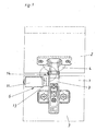
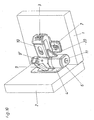
- the Fig. 1 to 5 show an embodiment in which an electric motor 6 is arranged laterally on the hinge arm 3.
- the hinge arm 3 itself is, as is known, aufklippsbar on an anchored in the furniture part 1 base plate 7. But it is also possible any other known in the prior art mounting variant.
- the motor 6 is fixed here with its motor housing 11 on the hinge arm 3.
- the housing 11 could also be arranged on each other stop part.
- a preferably electrically switchable coupling 13 is provided between the gear 17 and the motor on the motor shaft 12. This is switchable at least between two states. In the so-called closed state, a force or torque of the motor 6 is transmitted, while in the so-called open state, no force or no torque is transmitted from the engine.
- the strength of the coupling force is variable.
- the output in the form of the motor shaft 12 can also cooperate with a aufwendinger designed gear if necessary.
- electromagnetic clutches 13 are used, since they can be built very small and easily controlled.
- the force or torque transmission takes place when the clutch 13 is closed by the gear 17 on a second gear 19 which is rigidly connected to the inner lever 8 'via the hinge axis 5'.
- the transmission of the rotational movement over the gears formed from the gears 17 and 19 has been selected in this embodiment, for reasons of space so that when opening and closing no collision between the motor 6 and furniture part 2 is formed.
- a transmission can also be used to lower or translate the rotational movement of the engine, if correspondingly higher or lower torques are required. With appropriate Space could be the engine but also directly on the axis 5 'of the inner joint lever 8' or the outer joint lever 8 flanged. It is also conceivable to use other axes of rotation 5 for transmitting the forces.
- an encoder 14 which has an encoder disk 15 and a light sensor 16 is provided in this exemplary embodiment.
- a motion or position sensor but also a potentiometer or the like could be used. It is advantageous to use absolutely measuring angle or length measuring systems, which can determine the absolute position of the toggle lever 8 'or axes 5' and thus the stop parts to each other even after a power cut or a power failure.
- the described sensors can be used both for position and velocity determination and as a switch for triggering or stopping a movement.
- the motor shaft 12 is arranged coaxially with or parallel to the or one of the joint axes 5, 5 '.
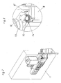
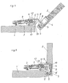
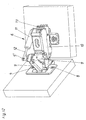
- the Fig. 6 to 8 show an embodiment according to the invention, in which the motor shaft 12 is arranged substantially perpendicular to the hinge axes 5, 5 '.
- the motor shaft 12 is arranged substantially perpendicular to the hinge axes 5, 5 '.
- a worm wheel 18 comprehensive worm gear is provided between the motor shaft 12 and the driven joint axes 5 'or articulated levers 8' a worm wheel 18 comprehensive worm gear.
- the sectional view according to Fig. 7 and 8th show as the sectional view according to 4 and 5 , via which components the transmission of the rotational movement from the motor shaft 12 to the articulated lever 8 'takes place.
- the gear 19 is rigidly connected to the hinge axis 5 'and the hinge lever 8'.
- the mounting bracket 20 holds the motor housing 11 in the optimal position for this arrangement, so that engagement of the worm 18 is ensured in the gear 19.
- the encoder and the freewheel or the clutch are integrated into the motor housing 11. So they are not visible from the outside.
- these types of motors can basically be used in all embodiments.
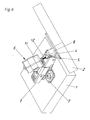
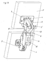
- the Fig. 9 to 13 show in embodiments how so-called wide-angle hinges can be equipped by means of motors 6 for pivoting the furniture parts 1 and 2.
- the wide-angle hinges have - as is known - seven joint axes 5, 5 ', wherein the outer articulated lever in the form of two relatively pivotable legs 9 and 9 'is formed.
- the motor housing 11 is in the embodiment according to the Fig. 9 to 11 arranged on a pivotable relative to the hinge arm 3 intermediate part 10.
- the motor shaft 12 simultaneously forms one of the joint axes 5 '.
- gear 17 On her sits a gear 17, which drives a second, rigidly on the driven leg 9 ', gear 21 drives.
- the arrangement of the gears 17 and 21 is particularly good in the sectional view according to Fig. 11 to see. This also shows the lever 23, which together with the leg 9 'allows the pivoting of the intermediate piece 10 relative to the hinge arm 3.
- a linear motor is used instead of a rotary motor.
- both the encoder for position and speed determination and the clutch or the freewheel is integrated.
- the movement of the hinge is effected by extending or retracting the motor shaft 12 into the motor housing 11.
- the motor housing 11 is pivotally mounted on the intermediate part 10 and the motor shaft 12 pivotally mounted on the hinge axis 5 '.
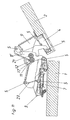
- FIGS. 14 and 15 shows an example of how a so-called frame hinge with a motor 6 - here a linear motor - can be equipped.
- a support lever 25 is arranged for this purpose, on which the motor housing 11 is pivotally supported.
- the retractable into the motor housing motor shaft 12 is pivotally mounted in the hinge cup 4.
- Fig. 16 shows a very simple embodiment.
- the engine over in the Fig. 1 to 15 not explicitly shown power lines 38 connected to a power source 37 and a switch 36.
- the motor 6 pivots about the motor shaft 12, the stop parts of the Furniture hinge 35.
- manually operable switch 36 has three switch positions. In a first, the motor 6 is driven so that it moves the furniture hinge 35 in the open position. In a second switching position of the switch 36, the furniture hinge 35 is pivoted in the direction of the closed position. In the third position, the motor 6 is de-energized, so he then performs no movement.
- a clutch present in the motor 6 is favorably opened or a freewheel activated, so that the furniture hinge can be pivoted by hand for emergency.
- switchable sensors can also be used by a movement or pressure and / or Werbergerschlagung the stop or furniture parts. These may be, for example, the previously mentioned encoders 14 or potentiometers or other angle or distance measuring systems, such as optical sensors or the like.
- the motor has an inductive motion sensor, by means of which it can be switched on and off during a movement of the stop parts, preferably in a direction-dependent manner. Is in the de-energized state, the clutch or the freewheel open, it can be conveniently provided mechanical holding devices that hold the furniture hinge 35 at rest in the respective position.
- a control device 29 takes over the regulation of the opening and closing movements of the furniture hinge 35.
- the control device 29 may additionally be connected to a switch 36 mentioned above and have further communication interfaces 30 for data transmission or for transferring control software.
- the control device 29 is conveniently designed as a microcontroller.
- the power line 38 it controls the motor 6.
- Via a first data line 39 it receives information about the actual position and / or actual speed of the abutment parts of the furniture hinge 35 from corresponding sensors in the motor 6 or in the furniture hinge 35 and a signal about the switch state of the coupling 13.
- Via second data line 40 receives them from also in the engine 6 and / or in the furniture hinge 35 can be arranged sensors switching commands for pivoting the stop parts or to stop the movement.
- the sensors for determining the actual position and actual speed can be used as sensors for the transmission of switching commands.
- the slight tapping or pulling on the furniture part 2 can be transmitted via the corresponding stop member to an encoder or a potentiometer.
- This sensor then passes the information on the first data line 39 to the control device 29, which interprets this signal when exceeding an adjustable threshold as a command to pivot the furniture hinge and controls the motor 6 accordingly.
- the motor 6 can be controlled so that it supports the movement started on the furniture part by hand or takes over entirely.
- the control device 29 can pivot in this way, the furniture hinge 35 via predeterminable angle ranges in the opening or closing direction, approach the full closing or opening positions but also dampen too vehement transferred by hand to the furniture part movements. It can also be provided that after a pulse on the furniture part, the furniture hinge 35 is brought into the complete closed or open position.
- control device 29 For accelerating and braking the abutment parts or the motor shaft 12, default values or functions can be stored in the control device 29, in which a certain reaction to a detected introduction of force is stored in the furniture part or the abutment part. It can also be provided that the control device brings the stop members in the closed position, if after a predetermined time interval no new drive signal for opening and / or closing has been detected. Of course, the control device 29 also takes over the activation of the clutch 13 via the third data line 41 and switches it at least between the closed and the opened state. The same applies to the optionally provided freewheel.
- the control device 29 may be arranged separately but also on the furniture hinge or integrated into this.
- Fig. 18 shows a control scheme for the operation of a motor hinge according to the invention by means of a control.
- the regulation and monitoring of the movement process during opening, closing and braking or stopping takes over the control device 29. It controls a power actuator in the form of an amplifier stage 32 at.
- This electronic power amplifier amplifies the signals of the controller 32, then to control the motor 6 accordingly.
- the task of the motor 6 is to convert both - preferably electrical - energy into mechanical energy in order to pivot the furniture parts against each other, as well as during the braking process to convert mechanical energy into, preferably electrical, energy.
- the coupling of the motor 6 to the moving furniture hinge 35 can be done as already stated via a coupling system 13 and optionally in addition to a gear for under or translation.
- the Control of the clutch 13 is also done by a signal line from the controller 29.
- the sensor system 34 converts the physical variables necessary for process control, such as actual position, actual speed (possibly rotational speed), acceleration (possibly torque) into, preferably electrical, signals and supplies a standardized (bus-capable) output signal the controller 29.
- a standardized (bus-capable) output signal the controller 29.
- an analog interface for example voltage interface with 0 to 10 volts
- a bus-capable interface is used for example an analog interface (for example voltage interface with 0 to 10 volts) or a bus-capable interface is used.
- An additional operating element 28 can be connected to the control device 29 via a corresponding analogue or bus-capable interface.
- the control element 28 may be designed in the form of switches 36, special actuators, for example, to support the manual operation, or optionally also as an emergency stop button.
- a display or visualization element 27 can optionally also be connected to the control device 29. Again, one will provide either an analog or a bus capable interface depending on the favorably type of display element.
- the control device 29 still has a communication interface 30 for parameterization and / or programming. This advantageously allows a connection to a PC or the like and can also be used to exchange information with a possible higher-level control or regulating device in which, for example, a plurality of drives are networked with each other.
- bus-capable interfaces are also used here.
- various components of the software 26 are provided. One of these is used for process control and, if necessary, autoparameterization of the control process.
- software components for controlling the interfaces can also be provided.
- diagnosis and parameterization of the drive various software components can be provided. Thus, the entire movement process during pivoting of the furniture parts can be visualized.
- software for manual parameterization of the drive system and for overall operation and diagnosis of the drive system can also be provided.
- the power supply 31 for the energy input into the overall system is conveniently a 24 volt DC power line. In the design of the power supply is generally assumed that a maximum mechanical power of about 5 watts is provided, resulting in an efficiency of about 25%, an electrical power of the drive of about 20 watts.
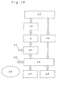
- Fig. 19 shows a flow diagram for the motorized pivoting of two connected via at least one inventive furniture hinge furniture parts, such as a furniture door and a furniture body.
- a time axis t is the opening angle a - measured between the furniture door and furniture body -, the coupling current I K and the motor current I M applied.
- ⁇ max means the maximum opening of the door.
- the clutch is in the closed state.
- the force or torque of the motor 6 is transmitted.
- I K 0, the clutch is open.
- the motor and clutch are de-energized.
- the clutch is open.
- the switch 36 receives the command to close the door.
- the clutch is closed.
- the engine is turned on. He now closes the door, which can be recognized by the course of ⁇ .
- the clutch opens at time t 7 .
- the engine is switched off at time t 8 .
- the door is closed by a mechanical locking system known from the prior art.
- the deceleration can be done by means of a motor or by means of a mechanical damper.
- Fig. 20 the sequence of movements is shown in an alternative form of control.
- the triggering of the closing and opening movement of the door is not carried out by actuation a switch 36 or the like but by a slight pivoting ⁇ s of the furniture door.
- This is detected by a corresponding sensor, such as an encoder or potentiometer, and forwarded to the control device 29.
- This interprets the pivoting when exceeding a presettable threshold as a switching command and closes at time t 1, the clutch.
- the engine is turned on to open the door.
- the sensor system Upon reaching a certain opening angle ⁇ at the time t a, the sensor system notices that the door is manually accelerated by a user in the opening direction.
- the controller then opens at time t a the clutch and turns off at t b the engine.
- the sensor notices that the door is no longer moved by hand.
- the control device 29 switches on the clutch at time t c and the motor at time t d again to fully open the door.
- the remaining process until reaching ⁇ max corresponds to that of the example according to FIG Fig. 19 .
- the closing operation begins from the time t 5 , as stated above.
- the triggering at the time t 5 can be done both by a slight pivoting of the door, as at ⁇ s or via a switch 36. Even when closing the door now the intervention of a person is shown in the closing process.
- the sensor registers that the door is manually accelerated.
- the clutch is opened.
- the engine is switched off at time t f .
- the sensor registers the end of the operation of the door by hand.
- the clutch is switched on again.
- the motor follows at time t h and closes the door until the mechanical closing system takes over the final closing on the residual travel ⁇ .
Landscapes
- Engineering & Computer Science (AREA)
- Mechanical Engineering (AREA)
- Power-Operated Mechanisms For Wings (AREA)
- Hinges (AREA)
- Closing And Opening Devices For Wings, And Checks For Wings (AREA)
Claims (38)
- Charnière de meuble pour l'assemblage pivotant d'au moins deux éléments d'un meuble, comportant au moins deux éléments de butée, pouvant être fixés chacun à un élément du meuble, où au moins l'un des éléments de butée est un godet de charnière (4) et au moins un des éléments de butée est un bras de charnière (3), qui peuvent être reliés l'un à l'autre de manière articulée par l'intermédiaire d'au moins un pivot d'articulation, caractérisée en ce que la charnière de meuble comporte au moins un moteur (6), de préférence un moteur électrique, destiné à faire pivoter les éléments de butée.
- Charnière de meuble selon la revendication 1, caractérisée en ce que la charnière de meuble est une charnière cadre.
- Charnière de meuble selon l'une quelconque des revendications 1 à 2, caractérisée en ce qu'au moins un des éléments de butée peut être clipsé sur une platine de base (7) apte à être fixée sur un élément du meuble (1, 2).
- Charnière de meuble selon l'une quelconque des revendications 1 à 3, caractérisée en ce que les éléments de butée peuvent être reliés entre eux par l'intermédiaire de quatre ou sept pivots d'articulation (5, 5').
- Charnière de meuble selon l'une quelconque des revendications 1 à 4, caractérisée en ce que les éléments de butée peuvent être reliés entre eux par au moins un, de préférence deux leviers d'articulation (8, 8').
- Charnière de meuble selon l'une quelconque des revendications 1 à 5, caractérisée en ce qu'au moins un levier d'articulation (8, 8') comporte deux branches (9) aptes à pivoter l'une par rapport à l'autre par l'intermédiaire d'un pivot d'articulation (5, 5').
- Charnière de meuble selon l'une quelconque des revendications 1 à 6, caractérisée en ce que le moteur (6) comporte un boîtier (11) et au moins un axe (12), l'axe (12) du moteur étant monté rotatif ou mobile longitudinalement par rapport au boîtier (11).
- Charnière de meuble selon la revendication 7, caractérisée en ce que le moteur (6), de préférence avec son boîtier (11), est disposé, de préférence fixé, sur un élément de butée.
- Charnière de meuble selon la revendication 7 ou 8, caractérisée en ce que le moteur (6), de préférence avec son boîtier (11), est disposé, de préférence fixé, sur un levier d'articulation (8) éventuellement présent.
- Charnière de meuble selon l'une quelconque des revendications 7 à 9, caractérisée en ce que le moteur (6), de préférence avec son boîtier (11), est attaché ou disposé sur le ou l'un des pivots d'articulation (5').
- Charnière de meuble selon l'une quelconque des revendications 7 à 10, caractérisée en ce que le moteur (6), de préférence par l'intermédiaire d'une roue dentée (17) ou vis sans fin (18), montée sur son axe (12), engrène avec un pivot d'articulation (5') ou une roue dentée (19) ou vis sans fin, montée sur le levier d'articulation (8').
- Charnière de meuble selon l'une quelconque des revendications 7 à 11, caractérisée en ce que l'axe (12) du moteur est monté coaxialement ou parallèlement au ou à l'un des pivots d'articulation (5, 5').
- Charnière de meuble selon l'une quelconque des revendications 7 à 11, caractérisée en ce que l'axe (12) du moteur est monté sensiblement perpendiculairement au ou à l'un des pivots d'articulation (5, 5').
- Charnière de meuble selon l'une quelconque des revendications 7 à 13, caractérisée en ce que le boîtier (11) du moteur est monté sur un des éléments de butée, et l'axe (12) du moteur, le cas échéant par l'intermédiaire d'un levier ou levier coudé, entre en prise sur le ou l'un des leviers d'articulation (8') ou sur le ou l'un des pivots d'articulation (5') de la charnière ou sur l'autre élément de butée.
- Charnière de meuble selon l'une quelconque des revendications 1 à 14, caractérisée en ce que le moteur (6) est un moteur rotatif ou un moteur linéaire.
- Charnière de meuble selon l'une quelconque des revendications 1 à 5, caractérisée en ce que le moteur (6) est un moteur à courant continu ou un moteur à courant alternatif.
- Charnière de meuble selon l'une quelconque des revendications 1 à 16, caractérisée en ce que le moteur (6) nécessite une tension de service, de préférence une tension continue, entre 5 V et 25 V, de préférence 24 V.
- Charnière de meuble selon l'une quelconque des revendications 1 à 17, caractérisée en ce que le moteur (6) a une puissance de 2 W à 30 W, de préférence de 4 W à 20 W.
- Charnière de meuble selon l'une quelconque des revendications 1 à 18, caractérisée en ce que le moteur (6) est apte à amortir ou freiner pendant un mouvement d'ouverture et/ou de fermeture le mouvement relatif des éléments de butée l'un par rapport à l'autre, de préférence en fonction d'au moins une valeur de référence ou d'une fonction de référence.
- Charnière de meuble selon la revendication 19, caractérisée en ce que le moteur (6) peut être atténué par voie inductive ou par une sollicitation de résistance.
- Charnière de meuble selon l'une quelconque des revendications 1 à 20, caractérisée en ce que la charnière de meuble, de préférence le moteur (6), comporte une roue libre, pouvant de préférence être connectée ou déconnectée.
- Charnière de meuble selon l'une quelconque des revendications 1 à 21, caractérisée en ce que dans un organe de sortie du moteur (6) est monté un embrayage (13), de préférence électromagnétique, qui peut être commuté, de préférence électriquement, au moins entre une position fermée, dans laquelle il transmet une force ou un couple de rotation du moteur (6), et une position ouverte, dans laquelle il ne transmet ni force ni couple de rotation du moteur (6).
- Charnière de meuble selon l'une quelconque des revendications 1 à 22, caractérisée en ce que le moteur (6) peut être connecté ou déconnecté par un mouvement ou une sollicitation de pression et/ou de traction des éléments de butée.
- Charnière de meuble selon la revendication 23, caractérisée en ce que la charnière de meuble, de préférence le moteur (6), comporte un capteur de déplacement (34), de préférence un codeur (14) ou un potentiomètre, déterminant de préférence des valeurs absolues, ou un capteur de sollicitation de pression et/ou de traction pour déclencher le moteur (6).
- Charnière de meuble selon la revendication 23 ou 24, caractérisée en ce que le moteur (6) comporte un capteur de déplacement inductif, par lequel il peut être déclenché lors d'un mouvement des éléments de butée.
- Charnière de meuble selon l'une quelconque des revendications 1 à 25, caractérisée en ce qu'elle comporte un dispositif de retenue mécanique, par lequel la charnière de meuble (35), en position de repos, est maintenue dans la position actuelle respective, de préférence dans la position de fermeture.
- Charnière de meuble selon l'une quelconque des revendications 1 à 26, caractérisée en ce que la charnière de meuble, de préférence le moteur (6), comporte un dispositif destiné à déterminer la position relative actuelle et/ou la vitesse relative actuelle d'au moins deux des éléments de butée l'un par rapport à l'autre.
- Charnière de meuble selon l'une quelconque des revendications 7 à 26, caractérisée en ce que le moteur (6) comporte un dispositif destiné à déterminer la position relative actuelle et/ou la vitesse relative actuelle de l'axe (12) du moteur par rapport au boîtier (11) du moteur.
- Charnière de meuble selon la revendication 27 ou 28, caractérisée en ce que le dispositif destiné à déterminer la position relative et/ou la vitesse relative actuelle est un codeur (14) ou potentiomètre, déterminant de préférence des valeurs absolues, ou le moteur est un moteur pas à pas.
- Charnière de meuble selon l'une quelconque des revendications 27 à 29, caractérisée en ce qu'elle comporte un dispositif de réglage (29) qui, moyennant l'utilisation d'au moins une valeur réelle de la position relative actuelle et/ou de la vitesse relative actuelle des éléments de butée, est apte à régler le moteur (6) en vue de l'accélération et/ou en vue du freinage des éléments de butée en fonction d'une valeur de référence ou d'une fonction de référence.
- Système comportant une charnière de meuble selon la revendication 30, caractérisé en ce qu'il comporte un dispositif de réglage (29) qui, moyennant l'utilisation d'au moins une valeur réelle de la position relative actuelle et/ou de la vitesse relative actuelle de l'axe (12) du moteur par rapport au boîtier (11) du moteur, est apte à régler le moteur (6) en vue de l'accélération et/ou en vue du freinage des éléments de butée en fonction d'une valeur de référence ou d'une fonction de référence.
- Système selon la revendication 30 ou 31, caractérisé en ce que le dispositif de réglage, moyennant l'utilisation d'au moins une valeur réelle d'un capteur de déplacement (34) éventuellement présent ou d'un capteur de sollicitation de pression et/ou de traction éventuellement présent, est apte à régler le moteur (6), de préférence en tenant compte de la valeur de référence ou de la fonction de référence, de telle sorte qu'une accélération ou un freinage des éléments de butée se déclenchent.
- Système selon l'une quelconque des revendications 30 à 32, caractérisé en ce que le dispositif de réglage est apte à régler le moteur (6), de telle sorte que celui-ci, de préférence en tenant compte d'au moins une valeur réelle de la position relative actuelle et/ou de la vitesse relative actuelle des éléments de butée ou de l'axe (12) du moteur par rapport au boîtier (11) du moteur, fait pivoter les éléments de butée d'une zone angulaire prédéterminée dans la direction d'ouverture ou la direction de fermeture.
- Système selon la revendication 30 ou 33, caractérisé en ce que le dispositif de réglage est apte à régler le moteur (6), de telle sorte que celui-ci, en fonction d'un signal d'un capteur de déplacement (34) éventuellement présent ou d'un capteur de sollicitation de pression et/ou de traction éventuellement présent, amène les éléments de butée dans la position de fermeture ou la position d'ouverture.
- Système selon l'une quelconque des revendications 30 à 34, caractérisé en ce que le dispositif de réglage est apte à régler le moteur (6), de telle sorte que, lorsque les éléments de butée sont en position ouverte, il les amène dans une position de fermeture après un intervalle de temps prédéterminé.
- Système selon l'une quelconque des revendications 30 à 35, caractérisé en ce que celui-ci, en plus de la charnière de meuble, comporte un capteur de déplacement ou capteur de sollicitation de pression et/ou de traction, pouvant être agencé sur un élément (1, 2) du meuble.
- Système selon l'une quelconque des revendications 30 à 36, comportant une charnière de meuble selon la revendication 24, caractérisé en ce que le dispositif de réglage (29) commute l'embrayage (13) entre la position fermée et la position ouverte.
- Système selon l'une quelconque des revendications 29 à 35, caractérisé en ce que le dispositif de réglage (29) est monté sur la charnière de meuble ou est intégré dans celle-ci.
Priority Applications (1)
| Application Number | Priority Date | Filing Date | Title |
|---|---|---|---|
| SI200630719T SI1929112T1 (sl) | 2005-09-28 | 2006-08-04 | Pohištveni šarnir |
Applications Claiming Priority (2)
| Application Number | Priority Date | Filing Date | Title |
|---|---|---|---|
| AT0158805A AT502621A1 (de) | 2005-09-28 | 2005-09-28 | Möbelscharnier |
| PCT/AT2006/000330 WO2007035971A1 (fr) | 2005-09-28 | 2006-08-04 | Charniere de meuble |
Publications (2)
| Publication Number | Publication Date |
|---|---|
| EP1929112A1 EP1929112A1 (fr) | 2008-06-11 |
| EP1929112B1 true EP1929112B1 (fr) | 2010-04-21 |
Family
ID=37393244
Family Applications (1)
| Application Number | Title | Priority Date | Filing Date |
|---|---|---|---|
| EP06760817A Not-in-force EP1929112B1 (fr) | 2005-09-28 | 2006-08-04 | Charniere de meuble |
Country Status (9)
| Country | Link |
|---|---|
| US (1) | US8677568B2 (fr) |
| EP (1) | EP1929112B1 (fr) |
| JP (1) | JP2009510284A (fr) |
| CN (1) | CN101273179B (fr) |
| AT (2) | AT502621A1 (fr) |
| DE (1) | DE502006006812D1 (fr) |
| ES (1) | ES2344424T3 (fr) |
| SI (1) | SI1929112T1 (fr) |
| WO (1) | WO2007035971A1 (fr) |
Cited By (1)
| Publication number | Priority date | Publication date | Assignee | Title |
|---|---|---|---|---|
| DE102009026142A1 (de) * | 2009-07-09 | 2011-01-13 | Paul Hettich Gmbh & Co. Kg | Rastbeschlag für eine Auszugsführung |
Families Citing this family (44)
| Publication number | Priority date | Publication date | Assignee | Title |
|---|---|---|---|---|
| AT505126B1 (de) * | 2007-05-07 | 2009-05-15 | Blum Gmbh Julius | Klappenantriebssystem |
| DE202007006690U1 (de) * | 2007-05-07 | 2008-09-11 | Hettich-Heinze Gmbh & Co. Kg | Klappenbeschlag |
| DE202007006689U1 (de) * | 2007-05-07 | 2008-09-18 | Hetal-Werke Franz Hettich Gmbh & Co. Kg | Antriebseinrichtung für einen Beschlag |
| AT505209B1 (de) * | 2007-05-07 | 2012-04-15 | Blum Gmbh Julius | Antrieb für ein bewegbares möbelteil |
| AT506756B1 (de) * | 2008-04-16 | 2013-03-15 | Grass Gmbh & Co Kg | Möbelscharnier |
| AT506904A1 (de) * | 2008-05-15 | 2009-12-15 | Blum Gmbh Julius | Möbelantrieb |
| AT507281B1 (de) * | 2008-08-29 | 2014-06-15 | Blum Gmbh Julius | Möbelantrieb |
| AT507282B1 (de) * | 2008-08-29 | 2013-04-15 | Blum Gmbh Julius | Automatische möbelklappentyperkennung |
| JP5183378B2 (ja) * | 2008-09-09 | 2013-04-17 | 京セラドキュメントソリューションズ株式会社 | 原稿送り装置の取付構造及びこれを搭載した画像形成装置 |
| AT507697B1 (de) * | 2008-12-17 | 2011-12-15 | Blum Gmbh Julius | Möbelscharnier mit rotationsdämpfer |
| AT508072B1 (de) * | 2009-03-19 | 2016-01-15 | Blum Gmbh Julius | Anordnung, umfassend ein Möbelscharnier und ein Antriebssystem |
| AT15239U1 (de) * | 2009-03-25 | 2017-04-15 | Blum Gmbh Julius | Möbelscharnier |
| DE102009042053A1 (de) * | 2009-09-08 | 2011-03-10 | Illinois Tool Works Inc., Glenview | Dämpfer |
| DE102010006816B4 (de) * | 2010-02-03 | 2017-05-18 | Grass Gmbh & Co. Kg | Scharnier für ein Möbelteil und Möbel |
| DE102010035555A1 (de) * | 2010-08-26 | 2012-03-01 | Linrot Holding Ag | Elektromotorischer Schwenkantrieb, insbesondere für Klappen, beispielsweise an Möbeln |
| DE202010014732U1 (de) * | 2010-10-28 | 2012-01-30 | Grass Gmbh | Vorrichtung zum Bewegen eines bewegbar aufgenommenen Möbelteils und Möbel |
| DE202010016154U1 (de) * | 2010-11-25 | 2012-02-29 | Grass Gmbh | Bewegungsvorrichtung für ein bewegliches Möbelteil |
| DE202010015793U1 (de) * | 2010-11-25 | 2012-03-01 | Grass Gmbh | Vorrichtung zum Bewegen eines Möbelteils mit einer Antriebseinheit und Möbel |
| DE202010016153U1 (de) * | 2010-11-25 | 2012-02-29 | Grass Gmbh | Bewegungsvorrichtung für ein bewegliches Möbelteil |
| ITMI20110067A1 (it) * | 2011-01-24 | 2012-07-25 | Salice Arturo Spa | Dispositivo di apertura per un anta oscillante di un mobile ed assieme comprendente una cerniera e detto dispositivo di apertura |
| DE202011100573U1 (de) | 2011-05-12 | 2012-08-13 | Grass Gmbh | Vorrichtung zum Bewegen eines bewegbaren Möbelteils und Möbel |
| DE202011100577U1 (de) * | 2011-05-12 | 2012-08-13 | Grass Gmbh | Möbelbeschlag für ein bewegbares Möbelteil und Möbel |
| JP5572226B2 (ja) * | 2011-08-31 | 2014-08-13 | スガツネ工業株式会社 | ダンパ付きヒンジ装置 |
| ITGO20110006A1 (it) * | 2011-10-20 | 2013-04-21 | N E M Nord Est Meccanica S N C | Sistema di apertura a rinvio angolare per banchi e vetrine |
| DE202012006799U1 (de) * | 2012-07-16 | 2013-10-17 | Grass Gmbh | Vorrichtung zum Bewegen eines an einem Möbelkorpus bewegbaren Möbelteils |
| DE202012009450U1 (de) * | 2012-10-01 | 2014-01-07 | Hetal-Werke Franz Hettich Gmbh & Co. Kg | Bewegungsvorrichtung für ein bewegbares Möbelteil |
| DE102012024375A1 (de) * | 2012-12-13 | 2014-06-18 | Kiekert Aktiengesellschaft | Vorrichtung und Verfahren zur Betätigung einer Kraftfahrzeug-Schließeinrichtung |
| US8561262B1 (en) * | 2012-12-19 | 2013-10-22 | King Slide Works Co., Ltd. | Damping device for hinge assembly |
| DE102013101040A1 (de) * | 2013-02-01 | 2014-08-07 | Hettich-Oni Gmbh & Co. Kg | Mehrgelenkscharnier mit Dämpfung |
| US20160047160A1 (en) * | 2013-02-27 | 2016-02-18 | Nam Duc HUYNH | Enclosure access apparatus and method |
| ITBO20130139A1 (it) * | 2013-03-29 | 2014-09-30 | Nuova Star Spa | Sistema di movimentazione per un'anta o sportello di un elettrodomestico ed elettrodomestico provvisto di detto sistema. |
| DE202013008777U1 (de) * | 2013-10-07 | 2015-01-08 | Grass Gmbh & Co. Kg | Scharnier für ein Möbelteil und Möbel |
| US9127490B2 (en) * | 2013-12-05 | 2015-09-08 | Lianhong Art Co., Ltd. | Transmission mechanism for dual-shaft hinge |
| US9890576B2 (en) * | 2015-07-29 | 2018-02-13 | Ford Global Technologies, Llc | Active door operation based on voice commands |
| US9869567B2 (en) | 2015-09-22 | 2018-01-16 | Apple Inc. | Portable computer sleep mode system sensors |
| CN106869662B (zh) * | 2015-12-10 | 2017-12-19 | 川湖科技股份有限公司 | 铰链及其缓冲装置 |
| CN106869661B (zh) * | 2015-12-10 | 2018-02-06 | 川湖科技股份有限公司 | 铰链及其缓冲装置 |
| AT16417U1 (de) * | 2016-02-26 | 2019-08-15 | Blum Gmbh Julius | Stellarmantrieb |
| CN106193887B (zh) * | 2016-07-05 | 2018-06-15 | 青岛海尔特种电冰柜有限公司 | 一种自动开关门装置及带有该装置的冷柜 |
| TWI610531B (zh) * | 2016-08-02 | 2018-01-01 | 緯創資通股份有限公司 | 可自動執行角度翻轉的樞軸機構、電子裝置及其方法 |
| US10912431B2 (en) * | 2018-07-10 | 2021-02-09 | Kohler Co. | Hinge assembly for toilet |
| EP3851622B1 (fr) | 2020-01-17 | 2022-03-23 | FLAP Competence Center kft | Dispositif d'entraînement permettant de déplacer une partie mobile d'un meuble ainsi qu'agencement de ferrure et meuble doté d'un tel dispositif d'entraînement |
| EP4012140A1 (fr) * | 2020-12-09 | 2022-06-15 | Athmer OHG | Porte pivotante à battant |
| AT527715A1 (de) * | 2023-11-03 | 2025-05-15 | Blum Gmbh Julius | Anordnung mit einem Möbelscharnier und mit einem Sockelfuß |
Family Cites Families (36)
| Publication number | Priority date | Publication date | Assignee | Title |
|---|---|---|---|---|
| GB211990A (en) | 1922-12-08 | 1924-03-06 | John Edward Delbridge | Improvements in hinges |
| US2912237A (en) * | 1957-06-06 | 1959-11-10 | Gen Motors Corp | Door operator |
| US3091426A (en) * | 1961-05-08 | 1963-05-28 | Arthur J Klein | Adjustable chair |
| US4440364A (en) * | 1981-09-08 | 1984-04-03 | Cone Steven S | Retractable aircraft step |
| US4497462A (en) * | 1983-03-28 | 1985-02-05 | The Boeing Company | Outward opening electrically powered plug-type cargo door |
| DE3518009A1 (de) * | 1985-05-18 | 1986-11-20 | Mainz & Mauersberger Alu-System GmbH, 4600 Dortmund | Vorrichtung zum motorischen heben und senken des oberteiles eines bestrahlungsgeraetes |
| US4929146A (en) * | 1987-11-13 | 1990-05-29 | U.S. Philips Corporation | Manipulator |
| DE3741712A1 (de) * | 1987-12-09 | 1989-06-22 | Hettich Paul Gmbh & Co | Moebelscharnier |
| DE59008924D1 (de) * | 1989-09-02 | 1995-05-24 | Vieler Gerd & Bernd Kg | Theke mit schwenkbeweglicher Frontscheibe. |
| DE9319914U1 (de) | 1993-12-24 | 1994-03-31 | Rothenhäusler, Erwin, 88214 Ravensburg | Antriebsvorrichtung für einen Fenster- oder Türflügel |
| FR2741905A1 (fr) * | 1995-12-05 | 1997-06-06 | Carlo Thierry Di | Paumelle electrique debrayable |
| JP4198213B2 (ja) | 1997-08-11 | 2008-12-17 | 株式会社三渡工業所 | ヒンジとヒンジ機構 |
| EP1199453A3 (fr) | 1998-05-08 | 2003-01-22 | Mitsubishi Heavy Industries, Ltd. | Système de lavage des injecteurs de carburant d'une turbine à gaz |
| JPH11324483A (ja) | 1998-05-11 | 1999-11-26 | Royal Electric Co Ltd | 自動開閉扉とその開閉装置 |
| US6045204A (en) * | 1998-10-13 | 2000-04-04 | Hexcel Corporation | Overhead stowage bins in aircraft |
| US6505381B1 (en) * | 1999-07-30 | 2003-01-14 | Trw Astro Aerospace | Pulley actuated translational hinge system |
| AT409288B (de) * | 2000-02-28 | 2002-07-25 | Blum Gmbh Julius | Möbelscharnier |
| US6513617B2 (en) * | 2000-07-26 | 2003-02-04 | Honda Giken Kogyo Kabushiki Kaisha | Vehicle hood apparatus |
| AT410118B (de) * | 2000-10-19 | 2003-02-25 | Blum Gmbh Julius | Scharnier |
| DE10117935A1 (de) * | 2001-04-10 | 2002-10-17 | Valeo Sicherheitssysteme Gmbh | Verfahren zum automatischen Betätigen einer Fahrzeugtür und Vorrichtung zur Durchführung dieses Verfahrens |
| DE10117933A1 (de) * | 2001-04-10 | 2002-10-17 | Valeo Sicherheitssysteme Gmbh | Kraftfahrzeug mit einer automatisch betätigbaren Fahrzeugtür |
| DE10117934B4 (de) * | 2001-04-10 | 2012-09-06 | Valeo Sicherheitssysteme Gmbh | Antrieb für Kraftfahrzeuge mit einer automatisch verschließbaren Fahrzeugtür |
| DE20115250U1 (de) * | 2001-07-06 | 2002-11-14 | Lautenschlaeger Mepla Werke | Dämpfungsvorrichtung |
| DE10222298B4 (de) | 2002-05-18 | 2010-11-11 | Valeo Sicherheitssysteme Gmbh | Vorrichtung zum Verschwenken einer Fahrzeugtür oder Fahrzeugklappe |
| WO2004065740A1 (fr) * | 2003-01-22 | 2004-08-05 | Edscha Ag | Charniere |
| AT502611B1 (de) * | 2003-05-16 | 2007-09-15 | Blum Gmbh Julius | Scharnier |
| EP1636100A2 (fr) * | 2003-06-24 | 2006-03-22 | Pi Squared Design Inc. | Procede et appareil pour structure amovible possedant des cotes a acces alternatif |
| DE20311189U1 (de) * | 2003-07-21 | 2003-09-25 | Arturo Salice S.P.A., Novedrate, Como | Hebevorrichtung für eine zweiflüglige Faltklappe oder -tür |
| DE10333925B4 (de) * | 2003-07-24 | 2007-03-22 | Grass Gmbh | Möbelscharnier mit Öffnungsautomatik, insbesondere für Möbeltüren |
| DE10341999B4 (de) * | 2003-09-11 | 2005-07-14 | Edscha Ag | Scharnier |
| ITMI20031950A1 (it) * | 2003-10-10 | 2005-04-11 | Agostino Ferrari Spa | Gruppo cerniera per la connessione articolata di un pannello ad apertura verticale ad un elemento di arredamento |
| DE202004011636U1 (de) * | 2004-03-12 | 2004-09-23 | MEPLA-WERKE LAUTENSCHLäGER GMBH & CO. KG | Dämpfungsvorrichtung für Möbelscharniere |
| ITMI20060007U1 (it) * | 2006-01-12 | 2007-07-13 | Elesa Spa | Cerniera avente un interruttore di sicurezza incorporato |
| US7832057B2 (en) * | 2006-10-05 | 2010-11-16 | The Hoffman Group International, Ltd. | Extendable multi-axis door hinge |
| US7971393B2 (en) * | 2006-10-30 | 2011-07-05 | GM Global Technology Operations LLC | Door actuation systems |
| US7552509B2 (en) * | 2006-11-15 | 2009-06-30 | King Slide Works Co., Ltd. | Hinge buffer device |
-
2005
- 2005-09-28 AT AT0158805A patent/AT502621A1/de not_active Application Discontinuation
-
2006
- 2006-08-04 WO PCT/AT2006/000330 patent/WO2007035971A1/fr not_active Ceased
- 2006-08-04 DE DE502006006812T patent/DE502006006812D1/de active Active
- 2006-08-04 JP JP2008532534A patent/JP2009510284A/ja active Pending
- 2006-08-04 SI SI200630719T patent/SI1929112T1/sl unknown
- 2006-08-04 EP EP06760817A patent/EP1929112B1/fr not_active Not-in-force
- 2006-08-04 CN CN200680035865.5A patent/CN101273179B/zh active Active
- 2006-08-04 AT AT06760817T patent/ATE465315T1/de active
- 2006-08-04 ES ES06760817T patent/ES2344424T3/es active Active
-
2008
- 2008-03-26 US US12/078,046 patent/US8677568B2/en not_active Expired - Fee Related
Cited By (1)
| Publication number | Priority date | Publication date | Assignee | Title |
|---|---|---|---|---|
| DE102009026142A1 (de) * | 2009-07-09 | 2011-01-13 | Paul Hettich Gmbh & Co. Kg | Rastbeschlag für eine Auszugsführung |
Also Published As
| Publication number | Publication date |
|---|---|
| SI1929112T1 (sl) | 2010-08-31 |
| ES2344424T3 (es) | 2010-08-26 |
| ATE465315T1 (de) | 2010-05-15 |
| AT502621A1 (de) | 2007-04-15 |
| US8677568B2 (en) | 2014-03-25 |
| JP2009510284A (ja) | 2009-03-12 |
| US20080172834A1 (en) | 2008-07-24 |
| WO2007035971A1 (fr) | 2007-04-05 |
| CN101273179A (zh) | 2008-09-24 |
| CN101273179B (zh) | 2015-06-10 |
| DE502006006812D1 (de) | 2010-06-02 |
| EP1929112A1 (fr) | 2008-06-11 |
Similar Documents
| Publication | Publication Date | Title |
|---|---|---|
| EP1929112B1 (fr) | Charniere de meuble | |
| EP1982030B1 (fr) | Procédé et dispositif de commande du mouvement de fermeture d'un élément de carrosserie de véhicules automobiles | |
| DE112008002316B4 (de) | System und Verfahren zum dynamischen Bremsen eines Fahrzeugverschlusssystems | |
| EP1795685B1 (fr) | Dispositif d'entraînement pour le déplacement motorisé d'une porte de véhicule ou similaire | |
| EP2164364B1 (fr) | Mécanisme d'entraînement pour une partie mobile de meuble | |
| AT508072B1 (de) | Anordnung, umfassend ein Möbelscharnier und ein Antriebssystem | |
| DE102017205605A1 (de) | Kraft-Schwenktür-Betätigungsglied mit integriertem Tür-Kontrollmechanismus | |
| DE102017204914A1 (de) | Kraft-Schwenktür-Betätigungsglied mit gelenkigem Verbindungsmechanismus | |
| DE202017007582U1 (de) | Stellvorrichtung | |
| WO2011138420A1 (fr) | Dispositif d'entraînement de porte à battant pivotant | |
| WO2008134786A1 (fr) | Système d'entraînement pour battant | |
| EP1867826A2 (fr) | Actionneur de volet | |
| DE102004017264A1 (de) | Steuervorrichtung für kraftbetriebene Schwenktür an Kraftfahrzeugen | |
| DE102017220326B4 (de) | Verfahren zum Betrieb einer Motorantriebsvorrichtung einer Fahrzeugschiebetür | |
| WO2006045289A1 (fr) | Dispositif servant a ouvrir et/ou fermer une partie de carrosserie rabattable | |
| DE10313440A1 (de) | Vorrichtung zum automatischen Verschwenken einer auch manuell betätigbaren Fahrzeugtür | |
| DE202010016982U1 (de) | Bewegungsvorrichtung | |
| DE102012209146A1 (de) | Betätigbare Klappenanordnung | |
| EP2477926B1 (fr) | Cabine d'ascenseur | |
| DE102007001068B4 (de) | Klappenantrieb für insbesondere Kraftfahrzeuge | |
| DE102005004571B4 (de) | Kraftunterstütztes Fahrzeugscharnier | |
| EP2206867B1 (fr) | Actionneur de porte destiné à l'actionnement d'un vantail | |
| EP4010555B1 (fr) | Entraînement de porte coulissante pour véhicule à moteur | |
| DE102009041036A1 (de) | Bremseinrichtung | |
| EP2078126B1 (fr) | Dispositif d'actionnement électromécanique pour battant ou analogue |
Legal Events
| Date | Code | Title | Description |
|---|---|---|---|
| PUAI | Public reference made under article 153(3) epc to a published international application that has entered the european phase |
Free format text: ORIGINAL CODE: 0009012 |
|
| 17P | Request for examination filed |
Effective date: 20080228 |
|
| AK | Designated contracting states |
Kind code of ref document: A1 Designated state(s): AT BE BG CH CY CZ DE DK EE ES FI FR GB GR HU IE IS IT LI LT LU LV MC NL PL PT RO SE SI SK TR |
|
| 17Q | First examination report despatched |
Effective date: 20081219 |
|
| GRAP | Despatch of communication of intention to grant a patent |
Free format text: ORIGINAL CODE: EPIDOSNIGR1 |
|
| DAX | Request for extension of the european patent (deleted) | ||
| GRAS | Grant fee paid |
Free format text: ORIGINAL CODE: EPIDOSNIGR3 |
|
| GRAA | (expected) grant |
Free format text: ORIGINAL CODE: 0009210 |
|
| AK | Designated contracting states |
Kind code of ref document: B1 Designated state(s): AT BE BG CH CY CZ DE DK EE ES FI FR GB GR HU IE IS IT LI LT LU LV MC NL PL PT RO SE SI SK TR |
|
| REG | Reference to a national code |
Ref country code: GB Ref legal event code: FG4D Free format text: NOT ENGLISH |
|
| REG | Reference to a national code |
Ref country code: CH Ref legal event code: EP |
|
| REG | Reference to a national code |
Ref country code: IE Ref legal event code: FG4D Free format text: LANGUAGE OF EP DOCUMENT: GERMAN |
|
| REF | Corresponds to: |
Ref document number: 502006006812 Country of ref document: DE Date of ref document: 20100602 Kind code of ref document: P |
|
| REG | Reference to a national code |
Ref country code: NL Ref legal event code: VDEP Effective date: 20100421 |
|
| REG | Reference to a national code |
Ref country code: ES Ref legal event code: FG2A Ref document number: 2344424 Country of ref document: ES Kind code of ref document: T3 |
|
| LTIE | Lt: invalidation of european patent or patent extension |
Effective date: 20100421 |
|
| PG25 | Lapsed in a contracting state [announced via postgrant information from national office to epo] |
Ref country code: NL Free format text: LAPSE BECAUSE OF FAILURE TO SUBMIT A TRANSLATION OF THE DESCRIPTION OR TO PAY THE FEE WITHIN THE PRESCRIBED TIME-LIMIT Effective date: 20100421 Ref country code: LT Free format text: LAPSE BECAUSE OF FAILURE TO SUBMIT A TRANSLATION OF THE DESCRIPTION OR TO PAY THE FEE WITHIN THE PRESCRIBED TIME-LIMIT Effective date: 20100421 Ref country code: SE Free format text: LAPSE BECAUSE OF FAILURE TO SUBMIT A TRANSLATION OF THE DESCRIPTION OR TO PAY THE FEE WITHIN THE PRESCRIBED TIME-LIMIT Effective date: 20100421 |
|
| REG | Reference to a national code |
Ref country code: IE Ref legal event code: FD4D |
|
| PG25 | Lapsed in a contracting state [announced via postgrant information from national office to epo] |
Ref country code: FI Free format text: LAPSE BECAUSE OF FAILURE TO SUBMIT A TRANSLATION OF THE DESCRIPTION OR TO PAY THE FEE WITHIN THE PRESCRIBED TIME-LIMIT Effective date: 20100421 Ref country code: LV Free format text: LAPSE BECAUSE OF FAILURE TO SUBMIT A TRANSLATION OF THE DESCRIPTION OR TO PAY THE FEE WITHIN THE PRESCRIBED TIME-LIMIT Effective date: 20100421 Ref country code: IS Free format text: LAPSE BECAUSE OF FAILURE TO SUBMIT A TRANSLATION OF THE DESCRIPTION OR TO PAY THE FEE WITHIN THE PRESCRIBED TIME-LIMIT Effective date: 20100821 |
|
| PG25 | Lapsed in a contracting state [announced via postgrant information from national office to epo] |
Ref country code: CY Free format text: LAPSE BECAUSE OF FAILURE TO SUBMIT A TRANSLATION OF THE DESCRIPTION OR TO PAY THE FEE WITHIN THE PRESCRIBED TIME-LIMIT Effective date: 20100526 Ref country code: PL Free format text: LAPSE BECAUSE OF FAILURE TO SUBMIT A TRANSLATION OF THE DESCRIPTION OR TO PAY THE FEE WITHIN THE PRESCRIBED TIME-LIMIT Effective date: 20100421 Ref country code: GR Free format text: LAPSE BECAUSE OF FAILURE TO SUBMIT A TRANSLATION OF THE DESCRIPTION OR TO PAY THE FEE WITHIN THE PRESCRIBED TIME-LIMIT Effective date: 20100722 |
|
| PG25 | Lapsed in a contracting state [announced via postgrant information from national office to epo] |
Ref country code: DK Free format text: LAPSE BECAUSE OF FAILURE TO SUBMIT A TRANSLATION OF THE DESCRIPTION OR TO PAY THE FEE WITHIN THE PRESCRIBED TIME-LIMIT Effective date: 20100421 Ref country code: EE Free format text: LAPSE BECAUSE OF FAILURE TO SUBMIT A TRANSLATION OF THE DESCRIPTION OR TO PAY THE FEE WITHIN THE PRESCRIBED TIME-LIMIT Effective date: 20100421 Ref country code: IE Free format text: LAPSE BECAUSE OF FAILURE TO SUBMIT A TRANSLATION OF THE DESCRIPTION OR TO PAY THE FEE WITHIN THE PRESCRIBED TIME-LIMIT Effective date: 20100421 Ref country code: PT Free format text: LAPSE BECAUSE OF FAILURE TO SUBMIT A TRANSLATION OF THE DESCRIPTION OR TO PAY THE FEE WITHIN THE PRESCRIBED TIME-LIMIT Effective date: 20100823 |
|
| PLBE | No opposition filed within time limit |
Free format text: ORIGINAL CODE: 0009261 |
|
| STAA | Information on the status of an ep patent application or granted ep patent |
Free format text: STATUS: NO OPPOSITION FILED WITHIN TIME LIMIT |
|
| BERE | Be: lapsed |
Owner name: JULIUS BLUM GMBH Effective date: 20100831 |
|
| PG25 | Lapsed in a contracting state [announced via postgrant information from national office to epo] |
Ref country code: SK Free format text: LAPSE BECAUSE OF FAILURE TO SUBMIT A TRANSLATION OF THE DESCRIPTION OR TO PAY THE FEE WITHIN THE PRESCRIBED TIME-LIMIT Effective date: 20100421 Ref country code: RO Free format text: LAPSE BECAUSE OF FAILURE TO SUBMIT A TRANSLATION OF THE DESCRIPTION OR TO PAY THE FEE WITHIN THE PRESCRIBED TIME-LIMIT Effective date: 20100421 Ref country code: CZ Free format text: LAPSE BECAUSE OF FAILURE TO SUBMIT A TRANSLATION OF THE DESCRIPTION OR TO PAY THE FEE WITHIN THE PRESCRIBED TIME-LIMIT Effective date: 20100421 |
|
| 26N | No opposition filed |
Effective date: 20110124 |
|
| PG25 | Lapsed in a contracting state [announced via postgrant information from national office to epo] |
Ref country code: MC Free format text: LAPSE BECAUSE OF NON-PAYMENT OF DUE FEES Effective date: 20100831 |
|
| REG | Reference to a national code |
Ref country code: CH Ref legal event code: PL |
|
| GBPC | Gb: european patent ceased through non-payment of renewal fee |
Effective date: 20100804 |
|
| PG25 | Lapsed in a contracting state [announced via postgrant information from national office to epo] |
Ref country code: LI Free format text: LAPSE BECAUSE OF NON-PAYMENT OF DUE FEES Effective date: 20100831 Ref country code: CH Free format text: LAPSE BECAUSE OF NON-PAYMENT OF DUE FEES Effective date: 20100831 |
|
| REG | Reference to a national code |
Ref country code: FR Ref legal event code: ST Effective date: 20110502 |
|
| PG25 | Lapsed in a contracting state [announced via postgrant information from national office to epo] |
Ref country code: BE Free format text: LAPSE BECAUSE OF NON-PAYMENT OF DUE FEES Effective date: 20100831 Ref country code: FR Free format text: LAPSE BECAUSE OF NON-PAYMENT OF DUE FEES Effective date: 20100831 |
|
| PG25 | Lapsed in a contracting state [announced via postgrant information from national office to epo] |
Ref country code: GB Free format text: LAPSE BECAUSE OF NON-PAYMENT OF DUE FEES Effective date: 20100804 |
|
| PG25 | Lapsed in a contracting state [announced via postgrant information from national office to epo] |
Ref country code: HU Free format text: LAPSE BECAUSE OF FAILURE TO SUBMIT A TRANSLATION OF THE DESCRIPTION OR TO PAY THE FEE WITHIN THE PRESCRIBED TIME-LIMIT Effective date: 20101022 Ref country code: BG Free format text: LAPSE BECAUSE OF FAILURE TO SUBMIT A TRANSLATION OF THE DESCRIPTION OR TO PAY THE FEE WITHIN THE PRESCRIBED TIME-LIMIT Effective date: 20100421 Ref country code: LU Free format text: LAPSE BECAUSE OF NON-PAYMENT OF DUE FEES Effective date: 20100804 |
|
| PG25 | Lapsed in a contracting state [announced via postgrant information from national office to epo] |
Ref country code: BG Free format text: LAPSE BECAUSE OF FAILURE TO SUBMIT A TRANSLATION OF THE DESCRIPTION OR TO PAY THE FEE WITHIN THE PRESCRIBED TIME-LIMIT Effective date: 20100721 |
|
| PGFP | Annual fee paid to national office [announced via postgrant information from national office to epo] |
Ref country code: ES Payment date: 20130716 Year of fee payment: 8 Ref country code: SI Payment date: 20130715 Year of fee payment: 8 Ref country code: AT Payment date: 20130828 Year of fee payment: 8 |
|
| PGFP | Annual fee paid to national office [announced via postgrant information from national office to epo] |
Ref country code: TR Payment date: 20130712 Year of fee payment: 8 |
|
| PGFP | Annual fee paid to national office [announced via postgrant information from national office to epo] |
Ref country code: IT Payment date: 20130806 Year of fee payment: 8 |
|
| PGFP | Annual fee paid to national office [announced via postgrant information from national office to epo] |
Ref country code: DE Payment date: 20131026 Year of fee payment: 8 |
|
| REG | Reference to a national code |
Ref country code: DE Ref legal event code: R119 Ref document number: 502006006812 Country of ref document: DE |
|
| REG | Reference to a national code |
Ref country code: AT Ref legal event code: MM01 Ref document number: 465315 Country of ref document: AT Kind code of ref document: T Effective date: 20140804 |
|
| PG25 | Lapsed in a contracting state [announced via postgrant information from national office to epo] |
Ref country code: IT Free format text: LAPSE BECAUSE OF NON-PAYMENT OF DUE FEES Effective date: 20140804 |
|
| REG | Reference to a national code |
Ref country code: SI Ref legal event code: KO00 Effective date: 20150317 |
|
| REG | Reference to a national code |
Ref country code: DE Ref legal event code: R119 Ref document number: 502006006812 Country of ref document: DE Effective date: 20150303 |
|
| PG25 | Lapsed in a contracting state [announced via postgrant information from national office to epo] |
Ref country code: AT Free format text: LAPSE BECAUSE OF NON-PAYMENT OF DUE FEES Effective date: 20140804 Ref country code: SI Free format text: LAPSE BECAUSE OF NON-PAYMENT OF DUE FEES Effective date: 20140805 |
|
| PG25 | Lapsed in a contracting state [announced via postgrant information from national office to epo] |
Ref country code: DE Free format text: LAPSE BECAUSE OF NON-PAYMENT OF DUE FEES Effective date: 20150303 |
|
| REG | Reference to a national code |
Ref country code: ES Ref legal event code: FD2A Effective date: 20150925 |
|
| PG25 | Lapsed in a contracting state [announced via postgrant information from national office to epo] |
Ref country code: ES Free format text: LAPSE BECAUSE OF NON-PAYMENT OF DUE FEES Effective date: 20140805 |
|
| PG25 | Lapsed in a contracting state [announced via postgrant information from national office to epo] |
Ref country code: TR Free format text: LAPSE BECAUSE OF NON-PAYMENT OF DUE FEES Effective date: 20140804 |