EP1929962A1 - Porte-aiguilles chirurgical permettant de faire des sutures - Google Patents
Porte-aiguilles chirurgical permettant de faire des sutures Download PDFInfo
- Publication number
- EP1929962A1 EP1929962A1 EP05753808A EP05753808A EP1929962A1 EP 1929962 A1 EP1929962 A1 EP 1929962A1 EP 05753808 A EP05753808 A EP 05753808A EP 05753808 A EP05753808 A EP 05753808A EP 1929962 A1 EP1929962 A1 EP 1929962A1
- Authority
- EP
- European Patent Office
- Prior art keywords
- head
- arm
- mobile
- needle
- needle holder
- Prior art date
- Legal status (The legal status is an assumption and is not a legal conclusion. Google has not performed a legal analysis and makes no representation as to the accuracy of the status listed.)
- Granted
Links
- 238000006073 displacement reaction Methods 0.000 claims description 14
- 230000000903 blocking effect Effects 0.000 claims description 3
- 210000003128 head Anatomy 0.000 description 58
- 230000005540 biological transmission Effects 0.000 description 6
- 210000003811 finger Anatomy 0.000 description 5
- 230000006870 function Effects 0.000 description 3
- 238000000926 separation method Methods 0.000 description 3
- 210000003813 thumb Anatomy 0.000 description 3
- 206010052428 Wound Diseases 0.000 description 2
- 208000027418 Wounds and injury Diseases 0.000 description 2
- 238000013459 approach Methods 0.000 description 2
- 210000000245 forearm Anatomy 0.000 description 2
- 239000000470 constituent Substances 0.000 description 1
- 210000003709 heart valve Anatomy 0.000 description 1
- 238000002513 implantation Methods 0.000 description 1
- 230000000750 progressive effect Effects 0.000 description 1
- 230000000284 resting effect Effects 0.000 description 1
- 230000035807 sensation Effects 0.000 description 1
- 238000006467 substitution reaction Methods 0.000 description 1
- 238000001356 surgical procedure Methods 0.000 description 1
Images




Classifications
-
- A—HUMAN NECESSITIES
- A61—MEDICAL OR VETERINARY SCIENCE; HYGIENE
- A61B—DIAGNOSIS; SURGERY; IDENTIFICATION
- A61B17/00—Surgical instruments, devices or methods
- A61B17/04—Surgical instruments, devices or methods for suturing wounds; Holders or packages for needles or suture materials
- A61B17/06—Needles ; Sutures; Needle-suture combinations; Holders or packages for needles or suture materials
- A61B17/062—Needle manipulators
-
- A—HUMAN NECESSITIES
- A61—MEDICAL OR VETERINARY SCIENCE; HYGIENE
- A61B—DIAGNOSIS; SURGERY; IDENTIFICATION
- A61B17/00—Surgical instruments, devices or methods
- A61B17/28—Surgical forceps
- A61B17/29—Forceps for use in minimally invasive surgery
- A61B2017/2926—Details of heads or jaws
- A61B2017/2927—Details of heads or jaws the angular position of the head being adjustable with respect to the shaft
-
- A—HUMAN NECESSITIES
- A61—MEDICAL OR VETERINARY SCIENCE; HYGIENE
- A61B—DIAGNOSIS; SURGERY; IDENTIFICATION
- A61B17/00—Surgical instruments, devices or methods
- A61B17/28—Surgical forceps
- A61B17/29—Forceps for use in minimally invasive surgery
- A61B2017/2926—Details of heads or jaws
- A61B2017/2932—Transmission of forces to jaw members
- A61B2017/2943—Toothed members, e.g. rack and pinion
Definitions
- the present invention relates to a surgical needle holder for stitch suturing, specifically to facilitate suturing in areas or parts that are difficult to access by the surgeon's hand or areas that require suturing in which manual manipulation of the needle is not possible, or in which it is more convenient to manipulate by means of a device.
- the object of the invention is to provide a needle-holding device that allows access to remote areas, in addition to enabling high-precision suturing, even in those cases in which the plane along which the needle is displaced coincides with the longitudinal axle of the needle holder, or remains close to it. That is, it allows movement of the needle along the aforementioned planes without having to perform complex arm movements to transmit the rotation movement.
- the function of the needle holders is that of extending the action of the surgeon's hand, allowing access to parts of the human body that could otherwise not be accessed by a hand, while increasing the strength of the hand so as to exert sufficient pressure on the needle to avoid it from slipping as it penetrates the tissues.
- Suturing is normally performed in such a manner that the needle plane is perpendicular to the longitudinal plane of the holder, so that once the holder is gripped, the rotating movement of the forearm (pronosupination) displaces the needle along its movement plane. But if the needle must be moved along a plane that is not perpendicular to the longitudinal axle of the holder, the degree of difficulty and imprecision increases, as the holder must not only rotate around its axle but also describe a translational movement relative to said axle, which on occasions is not possible due to the limited space provided by access wounds.
- electromechanical devices surgical robots, which are really telemanipulators
- the surgical needle holder of the invention has been conceived to solve the aforementioned problems, as it is configured in such a manner as to manipulate and move needles along any plane parallel to the longitudinal axle of the device.
- the needle holder is comprised of two arms, namely a mobile arm and fixed arm, the latter being longer than the former, with the peculiarity that both arms end in expansions in the form of scissor grip eyes for introducing the fingers and correspondingly actuating said mobile arm.
- the fixed arm extends, from the end of the mobile arm, along a segment of considerable length, on the free end of which a head is mounted which enables two possible movements, a rotating movement to perform the necessary movements while suturing, and an opening and closing movement to release or adequately grip the needle.
- the device or needle holder assembly includes means by which to carry out the movements of the aforementioned head.
- the head is comprised of a fixed and mobile part, which opens and closes to release or grip the needle, both parts forming a clamp which is mounted on the same axle of a pulley by means of which the head rotates.
- the actuation of the two parts that comprise the actual clamp or head, to open or close it is carried out by actuating a pawl mounted on the fixed arm.
- a cable is disposed between the pawl and the mobile part of said clamp or head which, in a determined position, is tensed, thereby pressing the mobile part of the clamp against the fixed part and therefore gripping the suture needle which in this type of instruments are known to be curved.
- the aforementioned actuating pawl is related to a ratchet on which said pawl is locked in any actuation position, said ratchet being complementarily pushed towards a blocking position by a spring, so that the manual actuation of the ratchet, in the manner of a second pawl, counter to the spring action, releases the ratchet from the pawl, thereby allowing detensioning of the cable so as to release the needle gripped by the clamp, as in this case the mobile part shall be displaced laterally outwards, becoming separated from the other fixed part and releasing the suture needle.
- the rotating actuation of the aforementioned head or clamp and therefore movement towards the right and left of the needle to enable its function is carried out by means of a rotating movement that is transmitted by a belt to the pulley related to the aforementioned head, said belt being related by its other end to a second pulley which is considered the driving pulley, disposed at the side of a mechanism box essentially comprised of two geared toothed wheels that rotate in opposite directions, i.e.
- Transmission of movement may also be rigid, using axles or gears, in substitution of the aforementioned pulleys and cable or belt.
- the head is comprised of a toothed wheel that comprises a body through which an axle that comes into contact with a mobile part that forms part of the head passes transversely, and logically through the wheel itself, in such a manner that said head may tilt towards opening and closing positions with respect to the fixed part of the body that also forms part of the toothed wheel, so as to release or grip the suture needle accordingly.
- the aforementioned head and toothed wheel assembly is mounted on the free end of the longer arm, in such a manner that the toothed wheel is disposed within a cavity of said arm, while the rest of the head body projects towards one of the sides, whereas the end of the pass-through axle projects towards the other side through the toothed wheel of the lateral body thereof, wherein a lateral part or plate comes into contact with the projecting end of the axle, the tilting movement of which can occupy two positions, one in which it pushes against the aforementioned end of the axle, therefore forcing it to project towards the other side, of the head itself, and come into contact with the mobile part thereof, thereby opening it; and another resting position in which the lateral plate does not come into contact with the aforementioned axle and therefore maintains the head in its open position.
- this lateral plate is actuated by an extension disposed at the end of the shorter arm articulation, which is mounted on an axle around which it may rotate so that said extension to the shorter arm comes into contact with the fore-end of the lateral plate, thereby producing the tilting movement thereof so that it may come into contact, by its other end, with the aforementioned closing axle of the head, having foreseen the downward extension of the aforementioned rotation axle of the shorter arm to form a type of fork, the branches of which are disposed in holes made for said purpose in a movable part adequately supported by guides disposed for said purpose underneath the fixed arm, in such a manner that said type of fork initially includes a transverse axle disposed by its ends in the holes of the brackets pertaining to the upper part of the fixed or longer arm so that, when actuated in a scissor-like manner, said mobile arm produces the upward or downward tilting thereof and therefore the displacement of the part disposed underneath and along the entire length of the fixed arm, said part having a tooth
- This second variant of the aforementioned embodiment involves neither pulleys nor tensioners, but rather the transmission is direct, in one case by means of the lateral plate that pushes the piston rod that closes the head and, in another, by means of the movable elongated part disposed underneath the fixed or longer arm, through which the toothed wheel that forms part of the head is rotated, thereby rotating said head, as in the preceding case, in one direction or other.
- the described surgical needle holder is operated by introducing the ring finger through the scissor grip eye disposed at the end of the fixed arm, while the thumb is introduced through the scissor grip eye of the mobile arm, thereby actuating the needle holder or device in question in a scissor-like manner.
- the suture needle is gripped or held in a plane perpendicular to that in which the head is closed, i.e. in a different manner to that in which the needle is gripped or held in the needle holder corresponding to the first embodiment, wherein said needle is gripped in a longitudinal plane, the grip of the second version being more effective, although the functionality of both is optimal.
- the lateral plate that comes into contact with the end of the axle associated to the head so as to open and close it may be disposed on the side of the head itself, acting directly on said head so as to close it, thereby eliminating the pushing piston rod and obviously the articulation means of said lateral plate against the fixed arm, although said lateral plate shall logically be articulated at a point in which its separation with respect to the main axle, originated by a force, in turn produces its separation from the end, pressing against the head so as to close it.
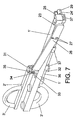
- the needle holder of the invention is comprised of two arms (1) and (2), the first being considerably longer than the second and both ending in expansions (3) by way of scissor grip eyes for fingers and by means of which to carry out manipulation or actuation, specifically of the mobile arm (2).
- the fixed arm (1) as of the aforementioned mobile arm (2), has an extension at the end of which a head (4) is disposed, comprised of a pulley (5) and laterally, on one side, a clamp (6) with a fixed branch (6') and a mobile branch (6"), the latter being capable of movement in a forward and backward direction with respect to the fixed branch (6'), with the peculiarity that said clamp (6) is mounted on an extension of the pulley (5) axle, thereby complementing the head assembly with a spring (7).
- the needle holder also includes a gear mechanism (8) which actuates the head, in such a manner that, by means of a belt or cable, not represented, and by means of a lateral belt (21) disposed in said mechanism (8), the movement is transmitted to the pulley (5) of the head (4), in order to produce rotation of the clamp (6).
- a gear mechanism (8) which actuates the head, in such a manner that, by means of a belt or cable, not represented, and by means of a lateral belt (21) disposed in said mechanism (8), the movement is transmitted to the pulley (5) of the head (4), in order to produce rotation of the clamp (6).
- said clamp (6) is capable of opening and closing for the lateral displacement of a mobile branch (6") that grips or releases the corresponding suture needle (9) which, as is already known, has a curved configuration.
- the actuation of the mobile arm (2), and therefore transmission of movement, is only produced in a downward direction, i.e. in the direction in which the holder closes, in such a manner that the aforementioned clamp (6) is opened and closed by means of a pawl (10) mounted articulately on the fixed arm (1), said pawl (10) being associated to a ratchet (11) that moves axially on said arm (1), counter to a spring (12) that causes the teeth (13) of the ratchet (11) to come into permanent contact with a toothed segment (14) of the pawl (10), for the purpose of blocking said pawl in any actuation position.
- a cable (17) passes between the pawl (10) and the mobile branch (6") of the clamp (6), fixed by one of its ends into a hole (16) and by the other end into a hole (16) of said mobile branch (6"), in such a manner that, when the pawl (10) is actuated, the clamp is closed and the needle (9) gripped so as to enable suturing, said closed position being blocked by means of the aforementioned ratchet (11), i.e. by the teeth thereof (13) which are geared to the toothed segment (14) of the pawl (10).
- the removal or separation of the needle (9) shall be carried out by actuating the ratchet (11) and displacing it slightly along the fixed arm (1), counter to the spring (12), thereby releasing the toothed segment (14) and therefore the pawl (10) which, due to the tension of the cable (17), makes it tilt, detensioning the cable.
- the direction of rotation of the clamp (6), and therefore the needle (9), so as to perform the suturing, is determined by the transmission of the rotation movement to the pulley (59 and therefore the clamp (6), said transmission being produced by the gear mechanism (8), which is mounted in correspondence with the mobile end (2) or, in other words, between the head 84) and the pawl (10) mounting area, in such a manner that said gear mechanism (8) comprises two toothed wheels (18), geared together, and therefore having opposite directions of rotation, although both wheels may rotate both in a clockwise and anti-clockwise direction, with the peculiarity that one of said wheels (18) is susceptible to having a pinion (19) selectively geared to it, due to which said pinion may be displaced with respect to its mounting axle so as to become geared to either wheel, thereby transmitting the rotation movement in either direction to the lateral and external pulley (21), between which and the head (4) pulley (5) the corresponding transmission belt shall be disposed.
- This gear mechanism (8) is actuated by means of the mobile arm (2) in a scissor-like manner, i.e. by introducing the thumb through the scissor grip eye (3) which, when actuated, acts on one of the wheels (18) so as to produce the rotation that shall be transmitted to the pulley (21), as mentioned earlier, in such a manner that said rotation is transmitted from said pulley to the pulley (5), producing the rotation of the clamp (6) and therefore the adequate movement of the needle (9) for suturing.
- the clockwise or anti-clockwise rotation of the pulley (5) is selected by displacing a mobile element (22) which acts as a selector.
- the needle holder does not comprise pulleys or tensioners, wherein movement is transmitted directly, as described below.
- the needle holder includes the fixed arm (1') and the mobile arm (2'), as mentioned earlier, with the scissor grip eye (3') being disposed at one of the ends of each of the arms, through which the fingers are introduced so as to actuate the needle holder.
- the corresponding head (4') disposed at the end of the fixed arm (1') comprises a body (24) with a pinion (23) at one of the ends, in such a manner that an axle or piston rod (25) passes through the body (24) and the pinion (23) itself, said axle or piston rod (25) being capable of moving axially, in correspondence with a transverse direction with respect to the fixed arm (1') itself, wherein one of the ends of the axle or piston rod (25) is disposed facing a plate (26) that is mounted laterally with respect to the fixed arm (1') by means of tilting pivots (27) that project from the respective side of the fixed arm (1').
- Said tilting movement of the lateral plate (26) to grip the suture needle is carried out by means of an appendix (30) disposed at the end of the mobile arm (2'), subsequent to the axle (31) with respect to which said mobile arm (2') may rotate. That is, when said mobile arm (2') is rotated with respect to the axle (31), said rotation produces the lateral displacement of the appendix (30) and therefore the outward pushing of the plate (26) with the opposite end thereof. That is, the part or section that extends from the articulation (27) of the plate (26) approaches the fixed arm (1'), thereby pushing the piston rod or axle (25), as mentioned earlier, with the previously described function.
- the aforementioned mobile arm (2') may tilt as represented in figure 9 , which shows, underneath the lower part of the rotation axle (31) a part that divides into two branches that form a type of fork (32), which move and tilt inside a pass (33) disposed for said purpose in the fixed arm (1') itself, said type of fork (32) being articulated between brackets (34) disposed collaterally to the pass (33) and in correspondence with the upper part of the arm (1') itself, in such a manner that when the mobile arm (2') is actuated upwards as represented in figure 9 , the tilting movement of the type of fork (32) is produced around the rotation axle (35) disposed between the brackets (34), said tilting movement causing the displacement of a part (36) disposed in a longitudinal manner and guided under the fixed arm (1), said guide being comprised of "U-shaped" profiles (37) disposed underneath the aforementioned fixed arm (1'), in such a manner that the displacement of said longitudinal part (36) is achieved upon the gearing of the type of fork (32)
- the mobile arm (2') may on one hand rotate around the axle (31) so as to open or close the head and therefore grip or release the suture needle and, on the other, said mobile arm (2') may tilt in such a manner as to produce rotation of the head and therefore of the suture needle, in either direction, so as to enable its functionality.
- the surgeon introduces his/her ring finger through the scissor grip eye (3) or (3') of the fixed arm (1) or (1'), while introducing the thumb through the scissor grip eye (3) or (3') of the mobile arm (2) or (2'), thereby actuating the needle holder in a scissor-like manner, in such a manner that the end of the fixed arm (1) or (1') is used to position the head in the part required by the surgeon.
- the figures show that it can be housed within a cavity disposed for said purpose next to the free end of the fixed arm (1'), a lateral hole being disposed in correspondence with said cavity through which a part of the body (24) corresponding to the head (4') passes and is positioned, also showing that, with the exception of said pinion (23), the rest of the head projects through one of the sides of the fixed arm (1'), even allowing the lateral pushing part or plate (26) of the piston rod or axle (25) to be disposed on said side.
- a maximum tilting movement shall produce a maximum displacement of said part, in such a manner that the tactile sensation reached by said maximum is achieved by means of a deformable and elastic part, not represented, which can be a spring, elastic sheet or similar, which generates a progressive resistance in the axle or fork (32), which informs the manipulator, i.e. the surgeon, that the part (32) is ungeared with respect to the pinion (23) and that, therefore, the head (4') moves freely at that point.
- a deformable and elastic part not represented, which can be a spring, elastic sheet or similar, which generates a progressive resistance in the axle or fork (32), which informs the manipulator, i.e. the surgeon, that the part (32) is ungeared with respect to the pinion (23) and that, therefore, the head (4') moves freely at that point.
- said deformable part is in contact with the end of the part (36) by the scissor grip eyes of the arm (1') and, when disposed opposite to the head upon moving, the zip (38) comes into contact with the end of the part (36), in such a manner that the part or body (24) may move freely.
- the head may be disposed according to the "starting angle" that best adapts to the intervention, providing an additional 140° of geared movement, corresponding to the maximum longitudinal displacement that the tilting movement of the fork (32) is capable of transmitting to the part (36), which in turn is transformed into the angular movement of the body (24) by means of the pinion (23).
Landscapes
- Health & Medical Sciences (AREA)
- Life Sciences & Earth Sciences (AREA)
- Surgery (AREA)
- Molecular Biology (AREA)
- Engineering & Computer Science (AREA)
- Biomedical Technology (AREA)
- Heart & Thoracic Surgery (AREA)
- Medical Informatics (AREA)
- Nuclear Medicine, Radiotherapy & Molecular Imaging (AREA)
- Animal Behavior & Ethology (AREA)
- General Health & Medical Sciences (AREA)
- Public Health (AREA)
- Veterinary Medicine (AREA)
- Surgical Instruments (AREA)
- Infusion, Injection, And Reservoir Apparatuses (AREA)
- Sewing Machines And Sewing (AREA)
Applications Claiming Priority (1)
| Application Number | Priority Date | Filing Date | Title |
|---|---|---|---|
| PCT/ES2005/000302 WO2006125835A1 (fr) | 2005-05-27 | 2005-05-27 | Porte-aiguilles chirurgical permettant de faire des sutures |
Publications (2)
| Publication Number | Publication Date |
|---|---|
| EP1929962A1 true EP1929962A1 (fr) | 2008-06-11 |
| EP1929962B1 EP1929962B1 (fr) | 2009-12-16 |
Family
ID=37451648
Family Applications (1)
| Application Number | Title | Priority Date | Filing Date |
|---|---|---|---|
| EP05753808A Expired - Lifetime EP1929962B1 (fr) | 2005-05-27 | 2005-05-27 | Porte-aiguilles chirurgical permettant de faire des sutures |
Country Status (6)
| Country | Link |
|---|---|
| US (1) | US20080200932A1 (fr) |
| EP (1) | EP1929962B1 (fr) |
| AT (1) | ATE451878T1 (fr) |
| DE (1) | DE602005018400D1 (fr) |
| ES (1) | ES2338342T3 (fr) |
| WO (1) | WO2006125835A1 (fr) |
Families Citing this family (27)
| Publication number | Priority date | Publication date | Assignee | Title |
|---|---|---|---|---|
| US7850683B2 (en) | 2005-05-20 | 2010-12-14 | Myoscience, Inc. | Subdermal cryogenic remodeling of muscles, nerves, connective tissue, and/or adipose tissue (fat) |
| US7713266B2 (en) | 2005-05-20 | 2010-05-11 | Myoscience, Inc. | Subdermal cryogenic remodeling of muscles, nerves, connective tissue, and/or adipose tissue (fat) |
| US7588583B2 (en) | 2005-09-14 | 2009-09-15 | Rhaphis Medical, Inc. | Suturing device, system and method |
| US9254162B2 (en) | 2006-12-21 | 2016-02-09 | Myoscience, Inc. | Dermal and transdermal cryogenic microprobe systems |
| US8409185B2 (en) | 2007-02-16 | 2013-04-02 | Myoscience, Inc. | Replaceable and/or easily removable needle systems for dermal and transdermal cryogenic remodeling |
| CN101677817B (zh) | 2007-03-15 | 2011-09-28 | 雷菲斯医药公司 | 用于不同针的可替换尖端缝合装置和系统 |
| US8298216B2 (en) | 2007-11-14 | 2012-10-30 | Myoscience, Inc. | Pain management using cryogenic remodeling |
| KR20110119640A (ko) | 2008-12-22 | 2011-11-02 | 마이오우사이언스, 인크. | 냉매 공급원과 전원이 통합된 한랭수술 시스템 |
| WO2010083110A1 (fr) | 2009-01-16 | 2010-07-22 | Rhaphis Medical, Inc. | Verrou de suture chirurgicale |
| JP5841605B2 (ja) * | 2010-10-08 | 2016-01-13 | ヘッドセンス メディカル リミテッド | 頭蓋内圧を測定する装置と方法 |
| EP2717786B1 (fr) | 2011-06-08 | 2018-08-08 | Suturenetics, Inc. | Dispositif de sutures à mâchoires décalées et système |
| JP4972224B1 (ja) * | 2011-11-25 | 2012-07-11 | 泉工医科工業株式会社 | 把持器、持針器及びアタッチメント |
| WO2013106860A1 (fr) | 2012-01-13 | 2013-07-18 | Myoscience, Inc. | Système de filtration de sonde cryogénique |
| WO2013106859A1 (fr) | 2012-01-13 | 2013-07-18 | Myoscience, Inc. | Aiguille cryogénique avec régulation de la zone de congélation |
| US9241753B2 (en) | 2012-01-13 | 2016-01-26 | Myoscience, Inc. | Skin protection for subdermal cryogenic remodeling for cosmetic and other treatments |
| US9017318B2 (en) | 2012-01-20 | 2015-04-28 | Myoscience, Inc. | Cryogenic probe system and method |
| US9295512B2 (en) | 2013-03-15 | 2016-03-29 | Myoscience, Inc. | Methods and devices for pain management |
| US9668800B2 (en) | 2013-03-15 | 2017-06-06 | Myoscience, Inc. | Methods and systems for treatment of spasticity |
| CN105208954B (zh) | 2013-03-15 | 2019-06-04 | 肌肉科技股份有限公司 | 低温钝性解剖方法和设备 |
| US9610112B2 (en) | 2013-03-15 | 2017-04-04 | Myoscience, Inc. | Cryogenic enhancement of joint function, alleviation of joint stiffness and/or alleviation of pain associated with osteoarthritis |
| EP3065658B1 (fr) | 2013-11-05 | 2021-03-31 | Pacira CryoTech, Inc. | Système de traitement cryochirurgical sécurisé |
| WO2017197323A1 (fr) | 2016-05-13 | 2017-11-16 | Lee Ann S | Procédés et systèmes de localisation et de traitement par une thérapie à froid |
| WO2019099677A1 (fr) | 2017-11-15 | 2019-05-23 | Myoscience, Inc. | Systèmes intégrés de thérapie à froid et de stimulation électrique pour localiser et traiter des nerfs et procédés associés |
| CN107813281B (zh) * | 2017-12-13 | 2024-07-19 | 蓝天宇 | 一种用于通过狭窄通道控制终端传动工具的控制夹头 |
| CN110226951B (zh) * | 2019-07-11 | 2024-08-27 | 上海凯利泰医疗科技股份有限公司 | 一种万向自锁式加压撑开器 |
| CN114504355B (zh) * | 2022-02-14 | 2024-02-13 | 郭朝辉 | 一种肝胆外科取石用辅助装置 |
| CN118680616B (zh) * | 2024-08-27 | 2024-10-29 | 北京软体机器人科技股份有限公司 | 一种多头夹持装置 |
Family Cites Families (5)
| Publication number | Priority date | Publication date | Assignee | Title |
|---|---|---|---|---|
| US3168097A (en) * | 1960-08-02 | 1965-02-02 | Porges | Needle holder having a rotating clamp for surgical sutures |
| US5797956A (en) * | 1995-10-10 | 1998-08-25 | Snowden-Pencer, Inc. | Surgical instrument handle and actuator means for heart surgery |
| JP3791893B2 (ja) * | 2000-04-27 | 2006-06-28 | オリンパス株式会社 | 外科用処置具 |
| DE60218240T2 (de) * | 2001-04-18 | 2007-11-22 | Olympus Corporation | Chirurgisches Instrument |
| US7166116B2 (en) * | 2003-06-23 | 2007-01-23 | Ethicon, Inc. | Tissue grasper/suture passer instrument |
-
2005
- 2005-05-27 AT AT05753808T patent/ATE451878T1/de not_active IP Right Cessation
- 2005-05-27 DE DE602005018400T patent/DE602005018400D1/de not_active Expired - Lifetime
- 2005-05-27 EP EP05753808A patent/EP1929962B1/fr not_active Expired - Lifetime
- 2005-05-27 US US11/915,484 patent/US20080200932A1/en not_active Abandoned
- 2005-05-27 ES ES05753808T patent/ES2338342T3/es not_active Expired - Lifetime
- 2005-05-27 WO PCT/ES2005/000302 patent/WO2006125835A1/fr not_active Ceased
Non-Patent Citations (1)
| Title |
|---|
| See references of WO2006125835A1 * |
Also Published As
| Publication number | Publication date |
|---|---|
| ATE451878T1 (de) | 2010-01-15 |
| WO2006125835A1 (fr) | 2006-11-30 |
| ES2338342T3 (es) | 2010-05-06 |
| EP1929962B1 (fr) | 2009-12-16 |
| US20080200932A1 (en) | 2008-08-21 |
| DE602005018400D1 (de) | 2010-01-28 |
Similar Documents
| Publication | Publication Date | Title |
|---|---|---|
| EP1929962B1 (fr) | Porte-aiguilles chirurgical permettant de faire des sutures | |
| EP1815809B1 (fr) | Poignée pour instruments chirurgicaux | |
| US9168050B1 (en) | End effector construction | |
| US11000269B2 (en) | Medical instrument | |
| JP6886459B2 (ja) | 遠隔アクセスツール用のエンドエフェクタ顎閉鎖伝達システム | |
| AU2005322693B2 (en) | An instrument, particularly for use in laparoscopic surgery | |
| RU2187249C2 (ru) | Хирургический инструмент | |
| US5454823A (en) | Suturing apparatus | |
| EP1958572B1 (fr) | Coupe-suture de blocage en son milieu | |
| EP2740420B1 (fr) | Outil de traitement | |
| AU2012302365B2 (en) | A surgical suture apparatus | |
| US20130331826A1 (en) | Surgical instrument | |
| JP2017127646A (ja) | 円形ニードルドライバ | |
| WO2013154158A1 (fr) | Dispositif médical de manipulation | |
| JP2009514562A (ja) | 縫合装置、システム及び方法 | |
| JP2007296322A (ja) | かみ合い機構を備えた医療器具 | |
| JP2013215507A (ja) | 医療用マニピュレータ | |
| JP2013215506A (ja) | 医療用マニピュレータ | |
| JP5909142B2 (ja) | 医療用マニピュレータ | |
| CA3005638C (fr) | Dispositif medical pour l'application d'une suture chirurgicale | |
| JP2004016661A (ja) | 外科用処置具 |
Legal Events
| Date | Code | Title | Description |
|---|---|---|---|
| PUAI | Public reference made under article 153(3) epc to a published international application that has entered the european phase |
Free format text: ORIGINAL CODE: 0009012 |
|
| 17P | Request for examination filed |
Effective date: 20080205 |
|
| AK | Designated contracting states |
Kind code of ref document: A1 Designated state(s): AT BE BG CH CY CZ DE DK EE ES FI FR GB GR HU IE IS IT LI LT LU MC NL PL PT RO SE SI SK TR |
|
| DAX | Request for extension of the european patent (deleted) | ||
| GRAP | Despatch of communication of intention to grant a patent |
Free format text: ORIGINAL CODE: EPIDOSNIGR1 |
|
| GRAS | Grant fee paid |
Free format text: ORIGINAL CODE: EPIDOSNIGR3 |
|
| GRAA | (expected) grant |
Free format text: ORIGINAL CODE: 0009210 |
|
| AK | Designated contracting states |
Kind code of ref document: B1 Designated state(s): AT BE BG CH CY CZ DE DK EE ES FI FR GB GR HU IE IS IT LI LT LU MC NL PL PT RO SE SI SK TR |
|
| REG | Reference to a national code |
Ref country code: GB Ref legal event code: FG4D |
|
| REG | Reference to a national code |
Ref country code: CH Ref legal event code: EP |
|
| REG | Reference to a national code |
Ref country code: IE Ref legal event code: FG4D |
|
| REF | Corresponds to: |
Ref document number: 602005018400 Country of ref document: DE Date of ref document: 20100128 Kind code of ref document: P |
|
| REG | Reference to a national code |
Ref country code: NL Ref legal event code: VDEP Effective date: 20091216 |
|
| PG25 | Lapsed in a contracting state [announced via postgrant information from national office to epo] |
Ref country code: LT Free format text: LAPSE BECAUSE OF FAILURE TO SUBMIT A TRANSLATION OF THE DESCRIPTION OR TO PAY THE FEE WITHIN THE PRESCRIBED TIME-LIMIT Effective date: 20091216 Ref country code: FI Free format text: LAPSE BECAUSE OF FAILURE TO SUBMIT A TRANSLATION OF THE DESCRIPTION OR TO PAY THE FEE WITHIN THE PRESCRIBED TIME-LIMIT Effective date: 20091216 Ref country code: SE Free format text: LAPSE BECAUSE OF FAILURE TO SUBMIT A TRANSLATION OF THE DESCRIPTION OR TO PAY THE FEE WITHIN THE PRESCRIBED TIME-LIMIT Effective date: 20091216 |
|
| REG | Reference to a national code |
Ref country code: ES Ref legal event code: FG2A Ref document number: 2338342 Country of ref document: ES Kind code of ref document: T3 |
|
| LTIE | Lt: invalidation of european patent or patent extension |
Effective date: 20091216 |
|
| PG25 | Lapsed in a contracting state [announced via postgrant information from national office to epo] |
Ref country code: PL Free format text: LAPSE BECAUSE OF FAILURE TO SUBMIT A TRANSLATION OF THE DESCRIPTION OR TO PAY THE FEE WITHIN THE PRESCRIBED TIME-LIMIT Effective date: 20091216 Ref country code: SI Free format text: LAPSE BECAUSE OF FAILURE TO SUBMIT A TRANSLATION OF THE DESCRIPTION OR TO PAY THE FEE WITHIN THE PRESCRIBED TIME-LIMIT Effective date: 20091216 |
|
| PG25 | Lapsed in a contracting state [announced via postgrant information from national office to epo] |
Ref country code: AT Free format text: LAPSE BECAUSE OF FAILURE TO SUBMIT A TRANSLATION OF THE DESCRIPTION OR TO PAY THE FEE WITHIN THE PRESCRIBED TIME-LIMIT Effective date: 20091216 |
|
| PG25 | Lapsed in a contracting state [announced via postgrant information from national office to epo] |
Ref country code: BG Free format text: LAPSE BECAUSE OF FAILURE TO SUBMIT A TRANSLATION OF THE DESCRIPTION OR TO PAY THE FEE WITHIN THE PRESCRIBED TIME-LIMIT Effective date: 20100316 Ref country code: EE Free format text: LAPSE BECAUSE OF FAILURE TO SUBMIT A TRANSLATION OF THE DESCRIPTION OR TO PAY THE FEE WITHIN THE PRESCRIBED TIME-LIMIT Effective date: 20091216 Ref country code: NL Free format text: LAPSE BECAUSE OF FAILURE TO SUBMIT A TRANSLATION OF THE DESCRIPTION OR TO PAY THE FEE WITHIN THE PRESCRIBED TIME-LIMIT Effective date: 20091216 Ref country code: PT Free format text: LAPSE BECAUSE OF FAILURE TO SUBMIT A TRANSLATION OF THE DESCRIPTION OR TO PAY THE FEE WITHIN THE PRESCRIBED TIME-LIMIT Effective date: 20100416 Ref country code: RO Free format text: LAPSE BECAUSE OF FAILURE TO SUBMIT A TRANSLATION OF THE DESCRIPTION OR TO PAY THE FEE WITHIN THE PRESCRIBED TIME-LIMIT Effective date: 20091216 Ref country code: IS Free format text: LAPSE BECAUSE OF FAILURE TO SUBMIT A TRANSLATION OF THE DESCRIPTION OR TO PAY THE FEE WITHIN THE PRESCRIBED TIME-LIMIT Effective date: 20100416 |
|
| PG25 | Lapsed in a contracting state [announced via postgrant information from national office to epo] |
Ref country code: CZ Free format text: LAPSE BECAUSE OF FAILURE TO SUBMIT A TRANSLATION OF THE DESCRIPTION OR TO PAY THE FEE WITHIN THE PRESCRIBED TIME-LIMIT Effective date: 20091216 Ref country code: BE Free format text: LAPSE BECAUSE OF FAILURE TO SUBMIT A TRANSLATION OF THE DESCRIPTION OR TO PAY THE FEE WITHIN THE PRESCRIBED TIME-LIMIT Effective date: 20091216 Ref country code: SK Free format text: LAPSE BECAUSE OF FAILURE TO SUBMIT A TRANSLATION OF THE DESCRIPTION OR TO PAY THE FEE WITHIN THE PRESCRIBED TIME-LIMIT Effective date: 20091216 |
|
| PLBE | No opposition filed within time limit |
Free format text: ORIGINAL CODE: 0009261 |
|
| STAA | Information on the status of an ep patent application or granted ep patent |
Free format text: STATUS: NO OPPOSITION FILED WITHIN TIME LIMIT |
|
| PG25 | Lapsed in a contracting state [announced via postgrant information from national office to epo] |
Ref country code: GR Free format text: LAPSE BECAUSE OF FAILURE TO SUBMIT A TRANSLATION OF THE DESCRIPTION OR TO PAY THE FEE WITHIN THE PRESCRIBED TIME-LIMIT Effective date: 20100317 Ref country code: CY Free format text: LAPSE BECAUSE OF FAILURE TO SUBMIT A TRANSLATION OF THE DESCRIPTION OR TO PAY THE FEE WITHIN THE PRESCRIBED TIME-LIMIT Effective date: 20091216 |
|
| 26N | No opposition filed |
Effective date: 20100917 |
|
| PG25 | Lapsed in a contracting state [announced via postgrant information from national office to epo] |
Ref country code: MC Free format text: LAPSE BECAUSE OF NON-PAYMENT OF DUE FEES Effective date: 20100531 |
|
| REG | Reference to a national code |
Ref country code: CH Ref legal event code: PL |
|
| PG25 | Lapsed in a contracting state [announced via postgrant information from national office to epo] |
Ref country code: DK Free format text: LAPSE BECAUSE OF FAILURE TO SUBMIT A TRANSLATION OF THE DESCRIPTION OR TO PAY THE FEE WITHIN THE PRESCRIBED TIME-LIMIT Effective date: 20091216 |
|
| PG25 | Lapsed in a contracting state [announced via postgrant information from national office to epo] |
Ref country code: CH Free format text: LAPSE BECAUSE OF NON-PAYMENT OF DUE FEES Effective date: 20100531 Ref country code: LI Free format text: LAPSE BECAUSE OF NON-PAYMENT OF DUE FEES Effective date: 20100531 |
|
| PG25 | Lapsed in a contracting state [announced via postgrant information from national office to epo] |
Ref country code: IE Free format text: LAPSE BECAUSE OF NON-PAYMENT OF DUE FEES Effective date: 20100527 |
|
| PGFP | Annual fee paid to national office [announced via postgrant information from national office to epo] |
Ref country code: DE Payment date: 20120601 Year of fee payment: 8 |
|
| PGFP | Annual fee paid to national office [announced via postgrant information from national office to epo] |
Ref country code: GB Payment date: 20120403 Year of fee payment: 8 |
|
| PG25 | Lapsed in a contracting state [announced via postgrant information from national office to epo] |
Ref country code: LU Free format text: LAPSE BECAUSE OF NON-PAYMENT OF DUE FEES Effective date: 20100527 Ref country code: HU Free format text: LAPSE BECAUSE OF FAILURE TO SUBMIT A TRANSLATION OF THE DESCRIPTION OR TO PAY THE FEE WITHIN THE PRESCRIBED TIME-LIMIT Effective date: 20100617 |
|
| PGFP | Annual fee paid to national office [announced via postgrant information from national office to epo] |
Ref country code: IT Payment date: 20120529 Year of fee payment: 8 |
|
| PG25 | Lapsed in a contracting state [announced via postgrant information from national office to epo] |
Ref country code: TR Free format text: LAPSE BECAUSE OF FAILURE TO SUBMIT A TRANSLATION OF THE DESCRIPTION OR TO PAY THE FEE WITHIN THE PRESCRIBED TIME-LIMIT Effective date: 20091216 |
|
| PGFP | Annual fee paid to national office [announced via postgrant information from national office to epo] |
Ref country code: ES Payment date: 20120321 Year of fee payment: 8 |
|
| PGFP | Annual fee paid to national office [announced via postgrant information from national office to epo] |
Ref country code: FR Payment date: 20130606 Year of fee payment: 9 |
|
| GBPC | Gb: european patent ceased through non-payment of renewal fee |
Effective date: 20130527 |
|
| PG25 | Lapsed in a contracting state [announced via postgrant information from national office to epo] |
Ref country code: DE Free format text: LAPSE BECAUSE OF NON-PAYMENT OF DUE FEES Effective date: 20131203 |
|
| REG | Reference to a national code |
Ref country code: DE Ref legal event code: R119 Ref document number: 602005018400 Country of ref document: DE Effective date: 20131203 |
|
| PG25 | Lapsed in a contracting state [announced via postgrant information from national office to epo] |
Ref country code: IT Free format text: LAPSE BECAUSE OF NON-PAYMENT OF DUE FEES Effective date: 20130527 |
|
| PG25 | Lapsed in a contracting state [announced via postgrant information from national office to epo] |
Ref country code: GB Free format text: LAPSE BECAUSE OF NON-PAYMENT OF DUE FEES Effective date: 20130527 |
|
| REG | Reference to a national code |
Ref country code: ES Ref legal event code: FD2A Effective date: 20140613 |
|
| PG25 | Lapsed in a contracting state [announced via postgrant information from national office to epo] |
Ref country code: ES Free format text: LAPSE BECAUSE OF NON-PAYMENT OF DUE FEES Effective date: 20130528 |
|
| REG | Reference to a national code |
Ref country code: FR Ref legal event code: ST Effective date: 20150130 |
|
| PG25 | Lapsed in a contracting state [announced via postgrant information from national office to epo] |
Ref country code: FR Free format text: LAPSE BECAUSE OF NON-PAYMENT OF DUE FEES Effective date: 20140602 |