EP1930218A2 - Ventilblock für eine Fahrzeugbremssteuereinheit und eine Fahrzeugbremssteuereinheit mit einem solchen Ventilblock - Google Patents
Ventilblock für eine Fahrzeugbremssteuereinheit und eine Fahrzeugbremssteuereinheit mit einem solchen Ventilblock Download PDFInfo
- Publication number
- EP1930218A2 EP1930218A2 EP20070023552 EP07023552A EP1930218A2 EP 1930218 A2 EP1930218 A2 EP 1930218A2 EP 20070023552 EP20070023552 EP 20070023552 EP 07023552 A EP07023552 A EP 07023552A EP 1930218 A2 EP1930218 A2 EP 1930218A2
- Authority
- EP
- European Patent Office
- Prior art keywords
- brake
- hydraulic pressure
- wheel
- mounting hole
- flow path
- Prior art date
- Legal status (The legal status is an assumption and is not a legal conclusion. Google has not performed a legal analysis and makes no representation as to the accuracy of the status listed.)
- Granted
Links
Images


Classifications
-
- B—PERFORMING OPERATIONS; TRANSPORTING
- B60—VEHICLES IN GENERAL
- B60T—VEHICLE BRAKE CONTROL SYSTEMS OR PARTS THEREOF; BRAKE CONTROL SYSTEMS OR PARTS THEREOF, IN GENERAL; ARRANGEMENT OF BRAKING ELEMENTS ON VEHICLES IN GENERAL; PORTABLE DEVICES FOR PREVENTING UNWANTED MOVEMENT OF VEHICLES; VEHICLE MODIFICATIONS TO FACILITATE COOLING OF BRAKES
- B60T8/00—Arrangements for adjusting wheel-braking force to meet varying vehicular or ground-surface conditions, e.g. limiting or varying distribution of braking force
- B60T8/32—Arrangements for adjusting wheel-braking force to meet varying vehicular or ground-surface conditions, e.g. limiting or varying distribution of braking force responsive to a speed condition, e.g. acceleration or deceleration
- B60T8/34—Arrangements for adjusting wheel-braking force to meet varying vehicular or ground-surface conditions, e.g. limiting or varying distribution of braking force responsive to a speed condition, e.g. acceleration or deceleration having a fluid pressure regulator responsive to a speed condition
- B60T8/36—Arrangements for adjusting wheel-braking force to meet varying vehicular or ground-surface conditions, e.g. limiting or varying distribution of braking force responsive to a speed condition, e.g. acceleration or deceleration having a fluid pressure regulator responsive to a speed condition including a pilot valve responding to an electromagnetic force
- B60T8/3615—Electromagnetic valves specially adapted for anti-lock brake and traction control systems
- B60T8/3675—Electromagnetic valves specially adapted for anti-lock brake and traction control systems integrated in modulator units
- B60T8/368—Electromagnetic valves specially adapted for anti-lock brake and traction control systems integrated in modulator units combined with other mechanical components, e.g. pump units, master cylinders
-
- B—PERFORMING OPERATIONS; TRANSPORTING
- B60—VEHICLES IN GENERAL
- B60T—VEHICLE BRAKE CONTROL SYSTEMS OR PARTS THEREOF; BRAKE CONTROL SYSTEMS OR PARTS THEREOF, IN GENERAL; ARRANGEMENT OF BRAKING ELEMENTS ON VEHICLES IN GENERAL; PORTABLE DEVICES FOR PREVENTING UNWANTED MOVEMENT OF VEHICLES; VEHICLE MODIFICATIONS TO FACILITATE COOLING OF BRAKES
- B60T8/00—Arrangements for adjusting wheel-braking force to meet varying vehicular or ground-surface conditions, e.g. limiting or varying distribution of braking force
- B60T8/32—Arrangements for adjusting wheel-braking force to meet varying vehicular or ground-surface conditions, e.g. limiting or varying distribution of braking force responsive to a speed condition, e.g. acceleration or deceleration
- B60T8/34—Arrangements for adjusting wheel-braking force to meet varying vehicular or ground-surface conditions, e.g. limiting or varying distribution of braking force responsive to a speed condition, e.g. acceleration or deceleration having a fluid pressure regulator responsive to a speed condition
- B60T8/40—Arrangements for adjusting wheel-braking force to meet varying vehicular or ground-surface conditions, e.g. limiting or varying distribution of braking force responsive to a speed condition, e.g. acceleration or deceleration having a fluid pressure regulator responsive to a speed condition comprising an additional fluid circuit including fluid pressurising means for modifying the pressure of the braking fluid, e.g. including wheel driven pumps for detecting a speed condition, or pumps which are controlled by means independent of the braking system
- B60T8/4031—Pump units characterised by their construction or mounting
-
- F—MECHANICAL ENGINEERING; LIGHTING; HEATING; WEAPONS; BLASTING
- F15—FLUID-PRESSURE ACTUATORS; HYDRAULICS OR PNEUMATICS IN GENERAL
- F15B—SYSTEMS ACTING BY MEANS OF FLUIDS IN GENERAL; FLUID-PRESSURE ACTUATORS, e.g. SERVOMOTORS; DETAILS OF FLUID-PRESSURE SYSTEMS, NOT OTHERWISE PROVIDED FOR
- F15B13/00—Details of servomotor systems ; Valves for servomotor systems
- F15B13/02—Fluid distribution or supply devices characterised by their adaptation to the control of servomotors
- F15B13/06—Fluid distribution or supply devices characterised by their adaptation to the control of servomotors for use with two or more servomotors
- F15B13/08—Assemblies of units, each for the control of a single servomotor only
- F15B13/0803—Modular units
- F15B13/0807—Manifolds
- F15B13/0814—Monoblock manifolds
-
- Y—GENERAL TAGGING OF NEW TECHNOLOGICAL DEVELOPMENTS; GENERAL TAGGING OF CROSS-SECTIONAL TECHNOLOGIES SPANNING OVER SEVERAL SECTIONS OF THE IPC; TECHNICAL SUBJECTS COVERED BY FORMER USPC CROSS-REFERENCE ART COLLECTIONS [XRACs] AND DIGESTS
- Y10—TECHNICAL SUBJECTS COVERED BY FORMER USPC
- Y10S—TECHNICAL SUBJECTS COVERED BY FORMER USPC CROSS-REFERENCE ART COLLECTIONS [XRACs] AND DIGESTS
- Y10S303/00—Fluid-pressure and analogous brake systems
- Y10S303/10—Valve block integrating pump, valves, solenoid, accumulator
-
- Y—GENERAL TAGGING OF NEW TECHNOLOGICAL DEVELOPMENTS; GENERAL TAGGING OF CROSS-SECTIONAL TECHNOLOGIES SPANNING OVER SEVERAL SECTIONS OF THE IPC; TECHNICAL SUBJECTS COVERED BY FORMER USPC CROSS-REFERENCE ART COLLECTIONS [XRACs] AND DIGESTS
- Y10—TECHNICAL SUBJECTS COVERED BY FORMER USPC
- Y10T—TECHNICAL SUBJECTS COVERED BY FORMER US CLASSIFICATION
- Y10T137/00—Fluid handling
- Y10T137/8593—Systems
- Y10T137/877—With flow control means for branched passages
- Y10T137/87885—Sectional block structure
Definitions
- the present invention relates to a vehicle brake control unit base body and a vehicle brake control unit.
- vehicle brake control units for example, as a hydraulic pressure circuit for a four-wheel vehicle brake control unit
- a hydraulic pressure circuit in which in addition to an anti-lock brake control for each wheel brake, a skid control and a traction control (hereinafter, these controls being referred collectively as a "behavior stabilizing control") are performed in such a state that a brake actuator such as a brake pedal is not operated.
- This hydraulic pressure circuit includes a brake output circuit for actuating two of four wheel brakes and another brake output circuit for actuating the remaining two wheel brakes.
- a control valve unit for adjusting magnitude of brake hydraulic pressure applied to the wheel brake is provided for each wheel brake. That is, two control valve units are provided for one brake output circuit.
- an anti-lock brake control can be performed on each wheel brake independently.
- a regulator for opening and closing a flow path between the hydraulic pressure source and the control valve units, and a pump for supplying brake fluid to a flow path between the regulator and the control valve units are provided for each brake output circuit, thereby the behavior stabilizing control is enabled.
- each brake output circuit a set of two electromagnetic valves (an inlet valve, an outlet valve) is provided for each control valve unit, and a electromagnetic valve (a cut-off valve) which closes when performing a interlocking brake control is provided in the regulator. Furthermore, a electromagnetic valve (a suction valve) which opens when performing a behavior stabilizing control is interposed.on an inlet side of the pump. In this configuration, with the two brake output circuits added together, twelve electromagnetic valves are used therein.
- a hydraulic pressure sensor for measuring a brake hydraulic pressure is tend to be provided in a hydraulic pressure circuit.
- a vehicle brake control unit which realizes a hydraulic pressure circuit including such a hydraulic pressure sensor there has been such a vehicle brake control unit, for example, as is described in Japanese Patent Unexamined Publication No. JP-A-2002-347595 .
- this vehicle brake control unit on one surface of a block (base body), formed are:
- a problem that the invention is to solve is how to provide a vehicle brake control unit base body and a vehicle brake control unit.
- a vehicle brake control unit base body for a vehicle brake control unit which includes:
- the brake control unit when the base body is applied to a brake control unit, the brake control unit can be made small in size while the twelve electromagnetic valves and the plurality of (three) hydraulic pressure sensors are provided in one surface of the base body. Furthermore, with the vehicle brake control unit to which the base body is applied, it becomes possible to implement multiple complex and highly accurate safety functions which involve the control of vehicle brakes.
- a vehicle brake control unit including:
- the brake control unit can be made small in size while the twelve electromagnetic valves and the plurality of (three) hydraulic pressure sensors are provided in one surface of the base body. Furthermore, it becomes possible to implement multiple complex and highly accurate safety functions which involve the control of vehicle brakes.
- the first brake output circuit is connected to the wheel brakes of a front wheel and a rear wheel
- the second brake output circuit is connected to the wheel brakes of the other front wheel and the other rear wheel and each of the wheel side brake hydraulic pressure sensors measures magnitude of the brake hydraulic pressure applied to the front wheel.
- a brake hydraulic pressure control can be implemented in which emphasis is placed on braking force control, thereby making it possible to enhance further the accuracy of the brake hydraulic pressure control.
- the first brake output circuit is connected to the wheel brakes of a front wheel and a rear wheel
- the second brake output circuit is connected to the wheel brakes of the other front wheel and the other rear wheel and each of the wheel side brake hydraulic pressure sensors measures magnitude of brake hydraulic pressure applied to the wheel brake of the front wheel or the rear wheel which constitutes a drive wheel.
- a brake hydraulic pressure control can be implemented in which emphasis is placed on traction control, thereby making it possible to enhance further the accuracy of the brake hydraulic pressure control.
- the vehicle brake control unit can be made small in size while having the plurality of (three) hydraulic pressure sensors. Furthermore, it becomes possible to implement multiple complex and highly accurate safety functions which involve the control of vehicle brakes.
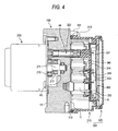
- a vehicle brake control unit U (hereinafter, referred to as a "brake control unit U") is configured to include a base body (a pump body) 100, a motor 200 which is assembled on a rear side of the base body 100, a control housing 300 which is assembled on a front side of the base body 100 and a control unit 400 which is accommodated in the control housing 300.
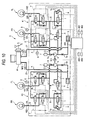
- the brake control unit U embodies a hydraulic pressure circuit shown in Fig. 10 .
- the brake control unit U includes a brake output circuit K1 for controlling two wheel brakes RL, FR among four wheel brakes RL, FR, FL, RR; and a brake output circuit K2 for controlling the remaining two wheel brakes FL, RR.
- independent anti-lock brake controls can be performed on four wheels by control valve units V which are provided individually for the wheel brakes RL, FR, FL, RR (that is, two control valve units per brake output circuit).
- a behavior stabilizing control is enabled by regulators R, suction valves 4 and pumps 6 which are provided for the brake output circuits k1, K2, respectively, working in cooperation with one another.
- the brake output circuit K1 applies brakes on left rear and right front wheels.
- the brake output circuit K1 constitutes a system running from an inlet port 21 to outlet ports 22L, 22R.
- a piping H11 which reaches an output port M11 of a master cylinder M constituting a hydraulic pressure source, is connected to the inlet port 21, and pipings H12, H12, which reach the wheel brakes RL, FR, respectively, are connected to the outlet ports 22L, 22R, respectively.
- the brake output circuit K2 applies brakes on right rear and left front wheels and constitutes a system running from an inlet port 23 to outlet ports 24L, 24R.
- a piping H21 which reaches an output port M12 of the master cylinder M constituting the same hydraulic pressure source as that for the brake output circuit K1, is connected to the inlet port 23.
- a brake pedal L which constitutes a brake operation element is connected. Namely, the four wheel brakes RL, FR, FL, RR can be applied only by exerting pedal effort on to the single brake pedal L.
- a regulator R Provided on the brake output circuit K1 for the front wheel are a regulator R, control valve units V, a suction valve 4, a reservoir 5, a pump 6, a damper 7, an orifice 7a, a hydraulic pressure source side brake hydraulic pressure sensor 8 and a wheel side brake hydraulic pressure sensor 9.
- output hydraulic pressure line A'' means a flow path (a fluid line) running from the inlet port 21 to the regulator R;
- wheel hydraulic pressure line B means a flow path running from the regulator R to the outlet ports 22L, 22R;
- suction hydraulic pressure line C means a flow path running from the output hydraulic pressure line A to the pump 6;
- discharge hydraulic pressure line D means a flow path running from the pump 6 to the wheel hydraulic pressure line B;
- release line E means a flow path running from the wheel hydraulic pressure line B to the suction hydraulic pressure line C.
- an "upstream side” indicates a side which connects to the master cylinder M or a master cylinder M side
- a “downstream side” indicates a side which connects to wheel brake RL/FR (FL/RR) or a wheel brake RL/FR (FL/RR) side.
- the regulator R has:
- the cut-off valve 1 is made up of a normally open type electromagnetic valve which is interposed between the output hydraulic pressure line A and the wheel hydraulic pressure line B.
- the cut-off valve 1 permits the brake fluid to flow from an upstream side to a downstream side thereof when in an open state and also the cut-off valve 1 interrupts the flow concerned when in a closed state.
- the normally open type electromagnetic valve which makes up the cut-off valve 1, is electrically connected to a control unit 400 via a solenoid coil which drives a valve body thereof.
- the solenoid coil When the solenoid coil is energized depending on a command from the control unit 400, the electromagnetic valve closes to interrupt the flow of brake fluid from the upstream side to the downstream side thereof.
- the solenoid coil is deenergized, the electromagnetic valve opens to permit the flow of brake fluid from the upstream side to the downstream side thereof.
- the check valve 1a is a valve which permits only a flow of brake fluid from an upstream side to a downstream side thereof and is connected parallel to the cut-off valve 1.
- the relief valve 1b is connected parallel to the cut-off valve 1 and opens when a difference between the brake hydraulic pressure in the output hydraulic pressure line A and the brake hydraulic pressure in the wheel hydraulic pressure line B reaches or exceeds a predetermined value.
- the control valve units V are provided for the wheel brakes RL, FR, one for each wheel brake.
- the control valve unit V has a function to switch over among:
- the inlet valve 2 is made up of a normally open type electromagnetic valve provided on the wheel hydraulic pressure line B.
- the inlet valve 2 permits the brake fluid to flow from an upstream side to a downstream side thereof when in an open state and also the inlet valve 2 interrupts the flow concerned when in a closed state.
- the normally open type electromagnetic valve which makes up the inlet valve 2 is electrically connected to the control unit 400 via a solenoid coil which drives a valve body thereof, so that the inlet valve 2 closes when the solenoid coil is energized based on a command from the control unit 400 and opens when the solenoid coil is deenergized.
- the check valve 2a is a valve which permits only a flow of brake fluid from a downstream side to an upstream side thereof and is connected parallel to the inlet valve 2.
- the outlet valve 3 is made up of a normally closed type electromagnetic valve interposed between the wheel hydraulic pressure line B and the release line E.
- the outlet valve 3 interrupts a flow of brake fluid from a wheel brake RL/FR (FL/RR) side to a reservoir 5 side thereof when in a closed state and the outlet valve 3 permits the flow when in an open state.
- the normally closed type electromagnetic valve which makes up the outlet valve 3, is electrically connected to the control unit 400 via a solenoid coil which drives a valve body thereof, so that the electromagnetic valve concerned opens when the solenoid coil is energized based on a command from the control unit 400 and closes when the solenoid coil is deenergized.
- the inlet valve 4 switches between a state in which the suction hydraulic pressure line C is opened and a state in which the suction hydraulic pressure line C is interrupted.
- the inlet valve 4 is made up of a normally closed type electromagnetic valve provided on the suction hydraulic pressure line C.
- the normally closed type electromagnetic valve which makes up the suction valve 4 is electrically connected to the control unit 400 via a solenoid coil which drives a valve body thereof, so that the electromagnetic valve concerned opens when the solenoid coil is energized based on a command from the control unit 400 and closes when the solenoid coil is deenergized.
- the reservoir 5 is provided on the release line E and has a function to temporarily store brake fluid which is relieved by each outlet valve 3 being opened.
- a check valve 5a is interposed between the reservoir 5 and the pump 6 for permitting only a flow of brake fluid from a reservoir 5 side to a pump 6 side thereof.
- the pump 6 is interposed between the suction hydraulic pressure line C which communicates with the output hydraulic pressure line A and the discharge hydraulic pressure line D which communicates with the wheel hydraulic pressure line B.
- the pump 6 is driven by the rotational force of the motor 200 and sucks the brake fluid stored temporarily in the reservoir 5 to discharge it to the discharge hydraulic pressure line D.
- the pump 6 sucks brake fluid stored in the master cylinder M, the output hydraulic pressure line A, the suction hydraulic pressure line C and the reservoir 5 to discharge it to the discharge hydraulic pressure line D, whereby a brake hydraulic pressure produced by operating the brake pedal L can be increased.
- the pump 6 can allow brake hydraulic pressure to be applied to the wheel brakes RL, FR (FL, RR) even in a state that the brake pedal L is not operated.
- damper 7 and the orifice 7a cooperate with each other to attenuate the pulsation of brake fluid discharged from the pump 6.
- the hydraulic pressure source side brake hydraulic pressure sensor 8 measures a brake hydraulic pressure in the output hydraulic pressure line A, that is, magnitude of brake hydraulic pressure in the master cylinder M. Only one hydraulic pressure source side brake hydraulic pressure sensor 8 is disposed for one of the brake output circuits (in the case of this embodiment, the brake output circuit K1), and no such sensor is provided on the other brake output circuit (in the case of this embodiment, the brake output circuit K2).
- the value of the brake hydraulic pressure measured by the hydraulic pressure source side brake hydraulic pressure sensor 8 is successively captured into the control unit 400, and whether or not a brake hydraulic pressure is outputted from the master cylinder M, that is, whether or not the brake pedal L is depressed is determined by the control unit 400. Furthermore, the behavior stabilizing control is implemented based on the magnitude of the brake hydraulic pressure measured by the hydraulic pressure source side brake hydraulic pressure sensor 8.
- the wheel side brake hydraulic pressure sensor 9 measures magnitude of brake hydraulic pressure applied to the wheel brake FR (FL) of the front wheel.
- the value of the brake hydraulic pressure measured by the wheel side brake hydraulic pressure sensor 9 is successively captured into the control unit 400, so that the anti-lock brake control and the behavior stabilizing control are implemented based on the magnitude of the brake hydraulic pressure measured by the wheel side brake hydraulic pressure sensor 9.
- the motor 200 is a common power supply for the pump 6 provided on the brake output circuit K1 on the front wheel side and the pump 6 provided on the brake output circuit K2 on the rear wheel side and operates based on a command from the control unit 400.
- the control unit 400 controls the opening and closing of the cut-off valves 1 of the regulators R, the inlet valves 2 and the outlet valves 3 of the control valve units V and the suction valves 4 and the operation of the motor 200 based on outputs from the hydraulic pressure source side brake hydraulic pressure sensor 8, the wheel side brake hydraulic pressure sensors 9, a wheel speed sensor 401 for the right front wheel, a wheel speed sensor 402 for the left front wheel, a wheel speed sensor 403 for the right rear wheel and a wheel speed sensor 404 for the left rear wheel.
- the plurality of solenoid coils which drives the plurality of electromagnetic valves are all deenergized by the control unit 400. Namely, in the normal brake control, the cut-off valves 1 and the inlet valves 2 are in the open state, while the outlet valves 3 and the suction valves 4 are in the closed state.
- An anti-lock brake control is executed when the wheels are likely to lock up and is realized by controlling the control valve units V which are associated, respectively, with the wheel brakes FL, RR, RL, FR of the wheels which are likely to lock up so as to selectively reduce, increase or hold constant the brake hydraulic pressures applied to the wheel brakes FL, RR, RL, FR.
- Whether the brake hydraulic pressures are selectively reduced, increased or held constant is determined by the control unit 400 based on wheel speeds obtained by the wheel speed sensor 401 for the right front wheel, the wheel speed sensor 402 for the left front wheel, the wheel speed sensor 403 for the right rear wheel and the wheel speed sensor 404 for the left rear wheel.
- the wheel hydraulic pressure line B is interrupted and the release line E is opened by the control valve unit V associated with the wheel brake FR.
- the inlet valve 2 is energized to be put in the closed state by the control unit 400
- the outlet valve 3 is energized to be put in the open state by the control unit 400.
- the motor 200 is driven by the control unit 400 so as to actuate the pump 6, so that brake fluid stored in the reservoir 5 is caused to flow back to the wheel hydraulic pressure line B via the discharge hydraulic pressure line D.
- both the wheel hydraulic pressure line B and the release line E are interrupted by the control valve unit V associated with the wheel brake FR.
- the inlet valve 2 is energized to be put in the closed state by the control unit 400, while the outlet valve 3 is deenergized to be put in the closed state by the control unit 400.
- the wheel hydraulic pressure line B is opened and the release line E is interrupted by the control valve unit V associated with the wheel brake FR.
- the inlet valve 2 is deenergized to be put in the open state by the control unit 400, while the outlet valve 3 is deenergized to be put in the closed state by the control unit 400.
- the opening and the opening time of the outlet valve 3 may be set such that the brake hydraulic pressure is not reduced excessively.
- the valve is controlled in this way, it becomes possible to perform a highly accurate brake control based on the magnitude of the brake hydraulic pressure which has been measured by the wheel side brake hydraulic pressure sensor 9, and when it is determined that the situation is over in which the wheel concerned is about to lock up and the brake hydraulic pressure which is being applied to the wheel brake FR be increased, the brake hydraulic pressure can be returned to a desired pressure on the spot.
- a behavior stabilizing control is such as to prevent disturbance to the behavior of the vehicle which occurs due to a change in driving conditions which occurs when running in rain or cornering on a snow-covered road.
- a behavior stabilizing control such as a skid control or traction control is started by the control unit 400.
- a behavior stabilizing control such as a skid control or traction control is started by the control unit 400.
- the cut-off valve 1 is energized to be put in the closed state by the control unit 400, while the suction valve 4 is energized to be put in the open state by the control unit 400. Furthermore, the inlet valves 2 which are not associated with the right front wheel are energized to be put in the closed state by the control unit 400, and in this state, the motor 200 is actuated to drive the pump 6.
- brake fluid stored in the master cylinder M, the output hydraulic pressure line A and the suction hydraulic pressure line C is caused to flow only into the wheel hydraulic pressure line B which communicates with the wheel brake FR by way of the pump 6 and the discharge hydraulic pressure line D.
- the brake hydraulic pressure is applied to the wheel brake FR, whereby the right front wheel is caused to slow.
- the brake control unit U is configured to include the base body (the pump body) 100, the motor 200, the control housing 300 and the control unit 400.
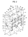
- the base body 100 is made up of an extruded material or a cast product which is formed substantially into a rectangular parallelepiped body and is made of aluminum alloy. A front side 11 of the obtained one is extruded or cast into a flat plane substantially free from irregularities..
- Two flow path configuring portions 100A, 100B are formed in the base body 100 so as to correspond to the two brake output circuits K1, K2 (refer to Fig. 10 ), respectively.
- the flow path configuring portion 100A associated with the brake output circuit K1 is formed in a right-hand half portion (a region which lies further rightwards than a center line X shown in the figures concerned) of the base body 100 as viewed from the side of the front side 11, while the flow path configuring portion 100B associated with the brake output circuit K2 is formed in a left-hand half portion (a region which lies further leftwards than the center line X shown in the figures concerned) of the base body 100.
- the flow path configuring portions 100A, 100B are formed substantially laterally symmetrical, and their interior configurations are the same.
- the flow path configuring portion 100A includes:
- the central mounting hole 31, the first inner mounting hole 32, the first outer mounting hole 33, the second inner mounting hole 34, the second outer mounting hole 35 and the third mounting hole 36 open in the same plane of the front side 11 of the flow path configuring portion 100A.
- hole diameters of the central mounting hole 31, the first inner mounting hole 32, the first outer mounting hole 33, the second inner mounting hole 34, the second outer mounting hole 35 and the third mounting hole 36 are all made the same in size.
- a piping H12 which reaches the wheel brake FR is connected to the outlet port 22L which lies inboards (leftwards in Fig. 5A ), while a piping H12 (refer to Fig. 10 ) which reaches the wheel brake RL is connected to the outlet port 22R which lies outboards (rightwards in Fig. 5A ).
- the inlet port 21 is a bottomed cylindrical hole and communicates with the central mounting hole 31 via the central flow path 51 (hereinafter, referred to as a "first flow path") .
- the first flow path 51 is made up of a horizontal hole 51a bored from a bottom side of the inlet port 21 towards the front side of the flow path configuring portion 100A and a vertical hole 51b bored downwards from the upper side 15 of the flow path configuring portion 100A.
- the vertical hole 51b intersects with the horizontal hole 51a and passes through a side wall of the central mounting hole 31 vertically (refer to Fig. 5A ).
- the outlet port 22L which lies inboards, is a bottomed cylindrical hole and communicates with the first inner mounting hole 32 via a second flow path 52.
- the second flow path 52 is made up of a vertical hole bored from a bottom side of the outlet port 22L, which lies inboards, towards the lower side 16 of the flow path configuring portion 100A and passes through a side wall of the first inner mounting hole 32 and a side wall of the wheel side sensor mounting hole 46 vertically to reach the second inner mounting hole 34.
- the outlet port 22R which lies outboards, is a bottomed cylindrical hole and communicates with the first outer mounting hole 33 via a fourth flow path 54.
- the fourth flow path 54 is made up of a vertical hole bored from a bottom side of the outlet port 22R, which lies outboards, towards the lower side 16 of the flow path configuring portion 100A and passes through a side wall of the first outer mounting hole 33 vertically to reach the second outer mounting hole 35.
- the central mounting hole 31 is a bottomed, stepped cylindrical hole into which a normally closed type electromagnetic valve 4s (refer to Fig. 1 ) is mounted which constitutes the suction valve 4 (refer to Fig. 10 ) and directly communicates with a side portion of the pump hole 38 at a bottom portion thereof.
- a connecting portion between the bottom portion of the central mounting hole 31 and the side portion of the pump hole 38 corresponds to the suction hydraulic pressure line C shown in Fig. 10 .
- the first inner mounting hole 32 is a bottomed, stepped cylindrical hole into which a normally open type electromagnetic valve 2s (refer to Fig. 1 ) is mounted, which constitutes the inlet valve 2 (refer to Fig. 10 ) of the control valve unit V associated with the wheel brake FR.
- the first inner mounting hole 32 communicates with the second inner mounting hole 34 via the second flow path 52 as shown in Fig. 5A and communicates with the first outer mounting hole 33 via a third flow path 53 as shown in Fig. 5B .
- the third flow path 53 is, as shown in Fig. 6B , made up of:
- the first outer mounting hole 33 is a bottomed, stepped cylindrical hole into which a normally open type electromagnetic valve 2s (refer to Fig. 1 ) is mounted, which constitutes the inlet valve 2 (refer to Fig. 10 ) of the control valve unit V associated with the wheel brake RL. Further, the first outer mounting hole 33 communicates with the second outer mounting hole 35 via the fourth flow path 54 as shown in Fig. 5A . Note that the fourth flow path 54 corresponds to the wheel hydraulic pressure line B shown in Fig. 10 .
- the second inner mounting hole 34 is a bottomed, stepped cylindrical hole into which a normally closed type electromagnetic valve 3s is mounted, which constitutes the outlet valve 3 (refer to Fig. 10 ) of the control valve unit V associated with the wheel brake FR.
- the second inner mounting hole 34 communicates with the reservoir hole 37 via a fifth flow path 55 which originates from a bottom portion thereof as shown in Fig. 5B .
- the fifth flow path 55 is made up of a vertical hole bored from a bottom side of the reservoir hole 37 so as to reach the bottom portion of the second inner mounting hole 34.
- the second outer mounting hole 35 is a bottomed, stepped cylindrical hole into which a normally closed type electromagnetic valve 3s is mounted, which constitutes the outlet valve 3 (refer to Fig. 10 ) of the control valve unit V associated with the wheel brake RL. Further, the second outer mounting hole 35 communicates with a bottom portion of the second inner mounting hole 34 via a sixth flow path 56 and also communicates with the reservoir hole 37 via the fifth flow path 55, as shown in Fig. 5B .
- the sixth flow path 56 passes through a bottom portion of the second outer mounting hole 35 horizontally and is made up of a horizontal hole 56a bored from the lateral side 14 of the flow path configuring portion 100A so as to reach the bottom portion of the second inner mounting hole 34. Note that an opening of this horizontal hole 56a is closed tightly by a plug member, not shown.
- the third mounting hole 36 is a bottomed, stepped cylindrical hole into which a normally open type electromagnetic valve 1s (refer to Fig. 1 ) is mounted, which constitutes the cut-off valve 1 (refer to Fig. 10 ).
- the third mounting hole 36 communicates with the inlet portion 21 via the first flow path 51 and a seventh flow path 57 at a side wall thereof as shown in Fig. 5A and, also communicates with the first inner mounting hole 32 and the first outer mounting hole 33 via an eighth flow path 58 and the third flow path 53, respectively, at a bottom portion thereof as shown in Fig. 5B .
- the seventh flow path 57 passes through the side wall of the third mounting hole 36 horizontally and is made up of a horizontal hole 57a bored from the lateral side 14 of the flow path configuring portion 100A so as to intersect the first flow path 51. Note that the horizontal hole 57a reaches a hydraulic pressure source side sensor mounting hole 45, which will be described later.
- the eighth flow path 58 is made up of;
- the reservoir hole 37 is a bottomed cylindrical hole into which the reservoir 5 (refer to Figs. 1, 10 ) is mounted and communicates with the pump hole 38 via a ninth flow path 59 as shown in Fig. 5B .
- the ninth flow path 59 is made up of a vertical hole bored from a bottom side of the reservoir hole 37 so as to reach a suction side of the pump hole 38.
- a one-way valve which constitutes the check valve 5a which is shown in Figs. 9 and 10 is mounted on the ninth flow path 59.
- the fifth flow path 55, the sixth flow path 56 and the ninth flow path 59 correspond to the release line E shown in Fig. 10 .
- the pump hole 38 is a stepped cylindrical hole into which the pump 6 (refer to Figs. 1, 10 ) is mounted, is formed so that a center line thereof passes through the center of the bearing hole 43 and communicates with the damper hole 39 via the eighth flow path 58.
- the vertical hole 58a of the eighth flow path 58 passes through a discharge side of the pump hole 38 vertically. Note that the eighth flow path 58 corresponds to the discharge hydraulic pressure line D shown in Fig. 10 .
- the damper hole 39 is a cylindrical hole which constitutes the damper 7 (refer to Fig. 10 ), and an opening thereof is closed tightly by a lid member, not shown.
- the wheel side sensor mounting hole 46 is a hole into which the wheel side brake hydraulic pressure sensor 9 (refer to Figs. 1, 10 ) is mounted, exhibits a bottomed cylindrical shape and is disposed on a downward extension of the outlet port 22L (in this embodiment, provided on the side lying inboards) of the outlet ports between the first inner mounting hole 32 and the second inner mounting hole 34. Specifically, the wheel side sensor mounting hole 46 is connected to the second flow path 52 with which a bottom portion thereof communicates below the outlet portion 22L and communicates with the outlet port 22L.
- the hydraulic pressure source side sensor mounting hole 45 into which the hydraulic pressure source side brake hydraulic pressure sensor 8 is mounted, is formed so as to straddle the center line X (refer to Fig. 1 ) of the base body 100 to extend to the flow path configuring portions 100A, 100B in a central portion (a boundary portion between the flow path configuring portions 100A, 100b) of the front side of the base body 100 which lies below the bearing hole 43 (refer to Fig. 5A ).
- the hydraulic pressure source side sensor mounting hole 45 is formed into a bottomed cylindrical shape, is disposed in such a manner that a central portion thereof is positioned on the center line X (refer to Fig.
- the seventh flow path 57 is made to open to a side wall of the hydraulic pressure source side sensor mounting hole 45, whereby the hydraulic pressure source side sensor mounting hole 45 communicates with the inlet port 21 via the seventh flow path 57 and the first flow path 51.
- the bearing hole 43 into which the output shaft 210 of the motor 200 is inserted and a terminal hole 44 into which a terminal rod 220 of the motor 200 is inserted are formed in the central portion (that is, the boundary portion between the flow path configuring portions 100A, 100B) of the base body 100.
- the bearing hole 43 is formed into a bottomed, stepped cylindrical shape and is made to open to the rear side 12 of the base body 100.
- the pump hole 38 (refer to Figs.
- 5A, 5B is made to open to a side wall of the bearing hole 43, and a ball bearing 212, which is fitted on an eccentric shaft portion 211 of the output shaft 210 so as to push on a plunger 162 of the pump 6, is accommodated in the vicinity of the opening in the pump hole 38.
- the terminal hole 44 is formed above the bearing hole 43 and passes through the base body 100 from the front to the rear thereof.
- Fig. 8A is a perspective view showing the normally open type electromagnetic valve 1s, 2s
- Fig. 8B is a sectional view showing a section of the normally open type electromagnetic valve 2s
- Fig. 8C is a perspective view showing the normally closed type electromagnetic valve 3s
- 4s is a sectional view showing a section of the normally closed type electromagnetic valve 3s.
- the normally open type electromagnetic valve 1s which constitutes the cut-off valve 1 and the normally open type electromagnetic valve 2s which constitutes the inlet valve 2 are put in such a state (an open state) that an opening 111a which is provided in a lateral side and an opening 11b which is provided in a bottom side thereof are made to communicate with each other when a magnet coil 340 (refer to Fig. 4 ) is deenergized by the control unit 400 (refer to Fig. 1 ), whereby a state results in which brake fluid can flow to pass through an interior of the electromagnetic valve concerned.
- a state results in which the communication between the opening 111a lying in the lateral side and the opening 111b lying in the bottom side thereof is interrupted (a closed state).
- the normally open type electromagnetic valve 2s includes mainly:
- the normally closed type electromagnetic valve 3s includes mainly:
- the reservoir 5 includes:
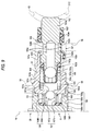
- the pump 6 includes a cylinder 161, a plunger 162, a return spring 163, a seal stopper 164, a suction valve unit 165, a cap 166, a discharge valve unit 167 and a discharge side filter 168.
- the cylinder 161 is made up of a bottomed cylindrical metal member whose inner circumferential surface is formed into a cylindrical surface, so as to form a suction valve chamber S1 which accommodates the suction valve unit 165.
- the cylinder 161 includes:
- the plunger 162 makes a reciprocating motion in an interior hollow space of the cylinder 161 in association with a rotary motion of the eccentric shaft portion 211 (refer to Fig. 1 ) of the motor 200.
- the plunger 162 includes:
- the contact portion 162a is loosely inserted in the pump hole 38 and protrudes into the bearing hole 43 for the motor 200 at a distal end portion thereof.
- an annular seal member 162e and a bush 162f which are brought into abutment with the pump hole 38, are mounted slidably on the contact portion 162a.
- the suction portion 162b is formed between the contact portion 162a and the sliding portion 162c and at least part thereof project from an opening in the cylinder 161.
- the sliding portion 162c is a portion which slides in the inner hollow portion of the small diameter portion 161a of the cylinder 161, and an outside diameter of the sliding portion 162c is made larger than outside diameters of the suction portion 162b and the valve seat portion 162d which lie adjacent thereto and is made slightly smaller than an inside diameter of the small diameter portion 161a of the cylinder 161.
- the valve seat portion 162d is formed closer to the suction valve chamber S1 than the sliding portion 162c, and an annular seal ring 162g is annularly placed on the circumference of the valve seat portion 162d.
- the seal ring 162g seals the interior of the suction valve chamber S1 fluid tightly while sliding along an inner circumferential portion of the cylinder 161.
- the return spring 163 is disposed in the suction valve chamber S1 in a compressed state and pushes the plunger 162 towards the bearing hole 43 by virtue of the restoring force thereof.
- the return spring 163 according to the embodiment is disposed between the cylinder bottom portion 161d of the cylinder 161 and the seal ring 162g annularly placed on the plunger 162, to thereby push on the plunger 162 via the seal ring 162g.
- the seal stopper 164 is a frame-shaped member for preventing the dislocation of the seal member 162e and includes a frame body 164a which is disposed so as to surround the suction portion 162b of the plunger 162 and a locking piece 164b which extends outwards from the frame body 164a towards the cylinder 161, whereby the seal stopper 164 is held in the cylinder 161 by the locking piece 164b being locked in the locking recessed portion 161f of the cylinder 161.
- the suction valve unit 165 opens and closes the suction path 162h and is accommodated in the suction valve chamber S1. More specifically, the suction valve unit 165 includes:
- the cap 166 is provided to be placed on the cylinder bottom portion 161d of the cylinder 161 from the outside so as to cover it and is made up of a bottomed cylindrical metal member which is separate from the cylinder 161. Formed on an inside of the cap 166 are a lager diameter recessed portion into which the cylinder bottom portion 161d is press fitted and a small diameter recessed portion 166b which is made smaller in diameter than the large diameter recessed portion 166a.
- the small diameter recessed portion 166b defines a discharge valve chamber S3 which accommodates therein the discharge valve unit 167 and the discharge side filter 168 together with the cylinder bottom portion 161d.
- An outer circumferential surface of the cap 166 is recessed in a circumferential direction thereof so as to provide an annular locking groove 166c.
- an outside diameter of an upper lid portion 166e which lies adjacent to the locking groove 166c in an upward direction is made smaller than an outside diameter of a lower lid portion 166d which lies adjacent to the locking groove 166c in a downward direction.
- the lower lid portion 166d is substantially the same as an inside diameter at portion lying further inwards than a stepped portion in an inlet portion of the pump hole 38 and is inserted in the portion concerned.
- the upper lid portion 166e projects from a bottom side of the stepped portion in the inlet portion of the pump hole 38 and a circumferential edge portion 166f of the projecting portion is chamfered.
- An outside diameter of a flow path configuring portion 166g of the cap 166 which lies below the lower lid portion 166d is made smaller than the outside diameter of the lower lid portion 166d.
- An annular space S4 which communicates with the eighth flow path 58 is defined by an outer circumferential surface of the flow path configuring portion 166g and the pump hole 38.
- an outlet hole 166h is formed in the flow path configuring portion 166g, which establish a communication between the discharge valve chamber S3 and the annular space S4. The outlet hole 166h functions as an orifice which mitigates pulsation occurring in association with the reciprocation of the plunger 162.
- the discharge valve unit 167 opens and closes the discharge path 161e formed in the cylinder bottom portion 161d of the cylinder 161 and is accommodated in the discharge valve chamber S3. More specifically, the discharge valve unit 167 is configured to include a spherical discharge valve body 167a which is disposed so as to close the discharge path 161e of the cylinder 161, and a discharge valve spring 167b which is disposed in a compressed state in the discharge valve chamber S3. The discharge valve body 167a is biased towards the discharge path 161e by virtue of the restoring force of the discharge valve spring 167b.
- the discharge side filter 168 filtrating the brake fluid discharged from the discharge path 161e is disposed so as to surround the discharge valve unit 167 within the discharge valve chamber S3, and is held by the cylinder 161 and the cap 166 therebetween so that at least portion thereof is compressed in an axial direction. More specifically, the discharge side filter 168 includes a filter main body 168B which allows brake fluid discharged from the discharge path 161e to pass therethrough to filtrate the brake fluid and a holding member 168A which holds the filter main body 168B.
- the motor 200 shown in Fig. 1 constitutes a power supply for the pump 6 and is integrally secured to the rear side 12 (refer to Fig. 4 ) of the base body 100.
- the eccentric shaft portion 211 is provided on the output shaft 210 of the motor 200.
- the ball bearing 212 is fitted on the eccentric shaft portion 211.
- the terminal rod 220 for supplying current to a rotor is provided above the output shaft 210 so as to project.
- the terminal rod 220 is inserted into the terminal hole 44 formed in a central upper portion of the base body 100, and a distal end portion thereof is connected to a connecting terminal 331 of the control housing 300.
- the control housing 300 includes a control case 310 which is integrally secured to the front side 11 of the base body 100 so as to cover the electromagnetic valves 1s to 4s, the hydraulic pressure source side brake hydraulic pressure sensor 8 and the wheel side brake hydraulic pressure sensor 9 and a control cover 320 which closes tightly an opening in the control cover 310.
- the control case 310 includes a mounting portion 311 which covers the front side 11 of the base body 100 and a connecter portion 312 in which connecting terminals to a battery and wheel speed sensors (not shown) are formed, and an endless seal member 313 (refer to Fig. 4 ) is mounted on the mounting portion 311.
- a connecter portion 312 in which connecting terminals to a battery and wheel speed sensors (not shown) are formed
- an endless seal member 313 (refer to Fig. 4 ) is mounted on the mounting portion 311.
- a support plate portion 314 in which a bus bar 330 is embedded is formed integrally in an interior of the control case 310.
- the solenoid coils 340 for driving the electromagnetic valves 1s to 4s installed in the base body 100 are mounted on the support plate 314.
- a connecting terminal (not shown) to the control unit 400 and connecting terminals 333 to the solenoid coils 340 are provided on the bus bar 330 so as to project therefrom.
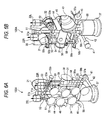
- control housing 300 since the interior of the control housing 300 is made to communicate with the outside via a recessed portion 41 and a vent hole 42 shown in Figs. 6A, 6B , an interior pressure of the control housing 300 is held at a similar level to the atmospheric pressure. Namely, the occurrence of intrusion of water and the like from the outside can be prevented by changing interior pressure of the control housing 300.
- a water vapor permeation preventive material not shown, is applied to the recessed portion 41 of the base body 100, there emerges no situation in which water or the like intrudes into the control housing 300.
- the control unit 400 shown in Fig. 1 is such that a semiconductor chip is installed on a substrate on which an electronic circuit is printed. Also, the control unit 400 controls the opening and closing of the electromagnetic valves 1s to 4s and the operation of the motor 200 based on information obtained from the various sensors such as the hydraulic pressure source side brake fluid sensor 8, the wheel side brake hydraulic pressure sensor 9, the wheel speed sensors 401, 402, 403, 404 (refer to Fig. 10 ) and programs which are stored therein in advance.
- the various sensors such as the hydraulic pressure source side brake fluid sensor 8, the wheel side brake hydraulic pressure sensor 9, the wheel speed sensors 401, 402, 403, 404 (refer to Fig. 10 ) and programs which are stored therein in advance.
- the brake fluid that has flowed into the eighth flow path 58 flows upwards through the annular space S4 and thereafter flows into the bottom portion of the first inner mounting hole 32 and the bottom portion of the first outer mounting hole 33 through the third flow path 53.
- the brake fluid that has flowed into the bottom portion of the first inner mounting hole 32 flows into the second flow path 52 through the interior of the electromagnetic valve 2s (refer to Fig. 1 ) which is being in the open state to thereby reach the wheel brake FR through the outlet port 22L.
- the brake fluid that has flowed into the bottom portion of the first outer mounting hole 33 flows into the fourth flow path 54 through the interior of the electromagnetic valve 2s (refer to Fig. 1 ) which is being in the open state to thereby reach the wheel brake RL through the outlet port 22R.
- the brake fluid which has flowed into the second flow path 52 which reaches the right front wheel brake FR flows into the wheel side sensor mounting hole 46. Then, the brake hydraulic pressure within the wheel hydraulic pressure line B is measured by the wheel side brake hydraulic pressure sensor 9, and the measured value is then captured into the control unit 400.
- the control unit 400 puts the inlet valve 2 associated with the wheel brake FR in the closed state and the outlet valve 3 in the open state. Then, the brake fluid which is applied to the wheel brake FR flows, as shown in Fig. 5A , into the side portion of the second inner mounting hole 34 through the outlet port 22L and the second flow path 52 and furthermore flows, as shown in Fig. 5B , into the fifth flow path 55 through the interior of the electromagnetic valve 3s (refer to Fig. 1 ) which is being in the open state to thereby flow into the reservoir hole 37.
- the brake fluid that has flowed into the first inner mounting hole 32 does not flow into the third flow path 53 but passes through a space between the side wall of the first inner mounting hole 32 and the outer circumferential surface of the electromagnetic valve 2s (refer to Fig. 1 ) to flow out towards the second inner mounting hole 34.
- the motor 200 is driven by the control unit 400 so as to actuate the pump 6.
- brake fluid stored in the reservoir hole 37 is sucked into the pump hole 38 by way of the ninth flow path 59 and is then discharged to the eighth flow path 58.
- the brake fluid passes through the outlet port 22R and the fourth flow path 54 to flow into the side portion of the second outer mounting hole 35. Furthermore, as shown in Fig. 5B , the brake fluid passes through the interior of the electromagnetic valve 3s (refer to Fig. 1 ) which is being in the open state and flows into the sixth flow path 56, then, passing through the fifth flow path 55 to flow into the reservoir hole 37.
- the wheel side brake hydraulic pressure sensor 9 is mounted in the wheel side sensor mounting hole 46 which communicates with the right front wheel brake FR via the outlet port 22L and the second flow path 52.
- the brake hydraulic pressure within the wheel hydraulic pressure line B which links to the wheel brake FR can be actually measured. Therefore, in the control unit 400, a delicate hydraulic pressure control can be implemented according to the brake hydraulic pressure so measured, and a brake hydraulic pressure which is best suitable for the wheel brake FR can be held in an ensured manner and with ease.
- a brake hydraulic pressure control is implemented in which emphasis is placed on braking force control. Furthermore, since the front wheels constitute the drive wheels, a brake hydraulic pressure control is also implemented in which emphasis is placed on traction control.
- the motor 200 is actuated to drive the pump 6 (refer to Fig. 9 ).
- brake fluid remaining in the inside of the pump hole 38 is discharged to the eighth flow path 58, as shown in Fig. 7 .
- the brake fluid discharged into the eighth flow path 58 flows into the first inner mounting hole 32 through the third flow path 53 and flows further to the second flow path 52 through the interior of the electromagnetic valve 2s (refer to Fig. 1 ) which is being in the open state, then reaching the wheel brake FR through the outlet port 22L.
- the brake hydraulic pressure within the wheel hydraulic pressure line B which links with the right front wheel brake FR can actually be measured by the wheel side brake hydraulic pressure sensor 9.
- a delicate hydraulic pressure control can be implemented so that the brake hydraulic pressure in the wheel hydraulic pressure line B becomes a desired value, thereby making it possible to implement a highly accurate brake control.
- the miniaturization of the unit can be realized while keeping the twelve electromagnetic valves 1s, 2s, 3s, 4s and the plurality of (three) hydraulic pressure sensors 8, 9, 9 on the one side (the front side 11) of the base body 100. Furthermore, in the brake control unit U to which the base body 100 so configured is applied, it becomes possible to implement the multiple complex and highly accurate safety functions which involve the control of the vehicle brakes.
- the wheel side brake hydraulic pressure sensors 9, 9 are mounted in the wheel side sensor mounting holes 4 6 which communicate, respectively, with the outlet ports 22L, 22R which link, respectively, with the wheel brakes FR, FL of the front wheels, so that magnitudes of brake hydraulic pressures which are applied to the wheel brakes FR, FL of the front wheels can be measured. Consequently, since the wheel side brake hydraulic pressure sensor 9 can be used to detect the brake hydraulic pressure of the front wheel to which more brake load is applied, the accuracy of the brake hydraulic pressure control can be enhanced further. In addition, since a brake hydraulic pressure sensor for detecting the brake hydraulic pressure of the rear wheel does not have to be provided, the miniaturization of the brake control unit U is attained, and the reduction in weight of the brake control unit u can also be attained.
- first inner mounting hole 32 and the second inner mounting hole 33 are disposed in the same height positions, the mounting holes may be disposed offset vertically.
- second inner mounting hole 34 and the second outer mounting hole 35 may also be disposed offset vertically.
- first inner mounting hole 32 and the second inner mounting hole 34 are disposed in such a manner that a line which connects centers of the respective mounting holes becomes parallel to the first flow path 51, the invention is not limited thereto and hence, they may be disposed offset horizontally.
- first outer mounting hole 33, the second outer mounting hole 35 and the third mounting hole 36 are disposed on the straight line so as to be aligned with one another, the invention is not limited thereto, and hence, they may be disposed offset horizontally.
- the arrangement of the electromagnetic valves and the hydraulic pressure sensors which are mounted in the mounting holes 31 to 36 may be changed.
- the normally closed type electromagnetic valves which constitute the output valves 3 may be mounted in the first inner mounting hole 32 and the first outer mounting hole 33
- the normally open type electromagnetic valves which constitute the inlet valves 2 may be mounted in the second inner mounting hole 34 and the second outer mounting hole 35.
- the brake hydraulic pressures applied to the wheel brakes FR, FL of the front wheels are made to be measured by the wheel side brake hydraulic pressure sensors 9, 9, it is possible to increase the accuracy of brake hydraulic pressure control even though a configuration may be adopted, in which the brake hydraulic pressures applied to the wheel brakes RR, RL of the rear wheels are measured irrespective of whether the drive wheels are constituted by the front wheels or the rear wheels.
- the invention can, of course, be applied to a rear-wheel-drive vehicle and a four-wheel-drive vehicle.
- a brake hydraulic pressure control can be implemented in which emphasis is placed on traction control
- the brake hydraulic pressures applied to the wheel brakes FR, FL of the front wheels are measured by the wheel side brake hydraulic pressure sensors 9, 9,
- a brake hydraulic pressure control can be implemented in which emphasis is placed on braking force control.
- a brake hydraulic pressure control can be implemented in which emphasis is placed on both traction control and braking force control.
Landscapes
- Physics & Mathematics (AREA)
- Engineering & Computer Science (AREA)
- Fluid Mechanics (AREA)
- Mechanical Engineering (AREA)
- Electromagnetism (AREA)
- Transportation (AREA)
- General Engineering & Computer Science (AREA)
- Regulating Braking Force (AREA)
Applications Claiming Priority (1)
| Application Number | Priority Date | Filing Date | Title |
|---|---|---|---|
| JP2006329185A JP4413219B2 (ja) | 2006-12-06 | 2006-12-06 | 車両用ブレーキ制御装置 |
Publications (3)
| Publication Number | Publication Date |
|---|---|
| EP1930218A2 true EP1930218A2 (de) | 2008-06-11 |
| EP1930218A3 EP1930218A3 (de) | 2010-08-25 |
| EP1930218B1 EP1930218B1 (de) | 2014-07-09 |
Family
ID=39048950
Family Applications (1)
| Application Number | Title | Priority Date | Filing Date |
|---|---|---|---|
| EP20070023552 Ceased EP1930218B1 (de) | 2006-12-06 | 2007-12-05 | Ventilblock für eine Fahrzeugbremssteuereinheit und eine Fahrzeugbremssteuereinheit mit einem solchen Ventilblock |
Country Status (3)
| Country | Link |
|---|---|
| US (1) | US8020946B2 (de) |
| EP (1) | EP1930218B1 (de) |
| JP (1) | JP4413219B2 (de) |
Cited By (5)
| Publication number | Priority date | Publication date | Assignee | Title |
|---|---|---|---|---|
| CN101633353B (zh) * | 2009-05-15 | 2014-02-26 | 浙江万向精工有限公司 | Abs座本体 |
| WO2014079615A1 (de) * | 2012-11-20 | 2014-05-30 | Robert Bosch Gmbh | Verfahren zum herstellen einer ventileinrichtung sowie entsprechende ventileinrichtung |
| WO2014090465A1 (de) * | 2012-12-14 | 2014-06-19 | Robert Bosch Gmbh | Hydraulikblock für ein hydraulikaggregat |
| EP2832598A4 (de) * | 2012-03-30 | 2016-02-24 | Nissin Kogyo Kk | Hydraulische bremsvorrichtung für ein fahrzeug |
| US11114873B2 (en) * | 2018-04-03 | 2021-09-07 | Walmart Apollo, Llc | Contingency battery charging system |
Families Citing this family (33)
| Publication number | Priority date | Publication date | Assignee | Title |
|---|---|---|---|---|
| US20080197697A1 (en) * | 2007-02-21 | 2008-08-21 | Takahiro Naganuma | Hydraulic brake pressure control apparatus for vehicle |
| DE102008029536B4 (de) * | 2008-04-28 | 2023-07-20 | Continental Automotive Technologies GmbH | Hydraulikaggregat |
| JP5454007B2 (ja) * | 2009-08-27 | 2014-03-26 | 株式会社アドヴィックス | 車両用液圧ブレーキの制御ユニット |
| JP5549324B2 (ja) * | 2010-03-31 | 2014-07-16 | 株式会社アドヴィックス | ブレーキ液圧制御ユニット |
| JP2011225009A (ja) * | 2010-04-15 | 2011-11-10 | Bosch Corp | ブレーキ液圧制御ユニットの製造方法 |
| JP5708296B2 (ja) * | 2011-06-24 | 2015-04-30 | 株式会社アドヴィックス | ブレーキ液圧制御装置 |
| DE102011078124A1 (de) * | 2011-06-27 | 2012-12-27 | Robert Bosch Gmbh | Bremssystem |
| US9248816B2 (en) * | 2012-02-07 | 2016-02-02 | Robert Bosch Gmbh | Hydraulic unit with variable damping |
| US20130299013A1 (en) * | 2012-05-14 | 2013-11-14 | Robert Bosch Gmbh | Hydraulic unit with flexible port location |
| DE102012208080A1 (de) * | 2012-05-15 | 2013-11-21 | Robert Bosch Gmbh | Hydraulikblock für eine schlupfgeregelte Fahrzeugbremsanlage |
| US9616866B2 (en) * | 2013-01-25 | 2017-04-11 | Autoliv Nissin Brake Systems Japan Co., Ltd. | Vehicular brake hydraulic pressure control apparatus |
| JP2015160464A (ja) * | 2014-02-26 | 2015-09-07 | 株式会社デンソー | ブレーキ液圧制御用アクチュエータ |
| US20170210364A1 (en) * | 2014-07-15 | 2017-07-27 | Robert Bosch Gmbh | Brake hydraulic pressure unit |
| JP2017007461A (ja) * | 2015-06-19 | 2017-01-12 | ローベルト ボッシュ ゲゼルシャフト ミット ベシュレンクテル ハフツング | ブレーキ液圧制御装置及びブレーキ液圧制御装置の製造方法 |
| JP6521831B2 (ja) * | 2015-10-21 | 2019-05-29 | 日立オートモティブシステムズ株式会社 | 液圧制御装置およびブレーキシステム |
| JP6544643B2 (ja) * | 2015-10-26 | 2019-07-17 | 日立オートモティブシステムズ株式会社 | 液圧制御装置およびブレーキシステム |
| DE102015223508A1 (de) * | 2015-11-27 | 2017-06-01 | Robert Bosch Gmbh | Pumpenaggregat für eine hydraulische Fahrzeugbremsanlage |
| DE102016209108A1 (de) * | 2015-12-02 | 2017-06-08 | Continental Teves Ag & Co. Ohg | Bremsdrucksteuergerät |
| DE102016225761A1 (de) * | 2016-09-07 | 2018-03-08 | Robert Bosch Gmbh | Hydraulikblock für ein Hydraulikaggregat einer Schlupfregelung einer hydraulischen Fahrzeugbremsanlage |
| KR102460740B1 (ko) * | 2016-09-07 | 2022-10-31 | 로베르트 보쉬 게엠베하 | 유압 차량 브레이크 시스템의 슬립 제어 시스템의 유압 어셈블리용 유압 블록 |
| KR102430253B1 (ko) * | 2016-11-30 | 2022-08-09 | 로베르트 보쉬 게엠베하 | 브레이크 제어부의 유압 유닛용 유압 블록 및 그 제조 방법 |
| JP2018090071A (ja) * | 2016-12-02 | 2018-06-14 | ローベルト ボッシュ ゲゼルシャフト ミット ベシュレンクテル ハフツング | ブレーキ液圧制御装置、モータサイクル用ブレーキシステム、及び、ブレーキ液圧制御装置の製造方法 |
| DE102017208310B4 (de) * | 2017-05-17 | 2023-02-16 | Mando Corporation | Ventilanordnung und diese Ventilanordnung enthaltendes Antiblockiersystem |
| JP6740975B2 (ja) * | 2017-07-18 | 2020-08-19 | 株式会社アドヴィックス | 液圧制御装置 |
| JP2020001417A (ja) * | 2018-06-25 | 2020-01-09 | 株式会社アドヴィックス | ブレーキ圧制御装置 |
| DE102018211435A1 (de) * | 2018-07-10 | 2020-01-16 | Robert Bosch Gmbh | Hydraulikblock für ein Hydraulikaggregat einer Bremsdruckregelung einer hydraulischen Fahrzeugbremsanlage |
| CN111348025B (zh) * | 2019-04-26 | 2021-11-19 | 京西重工(上海)有限公司 | 电液制动系统及使用其来防止车辆的车轮滑移的方法 |
| DE102019212353A1 (de) * | 2019-08-19 | 2021-02-25 | Robert Bosch Gmbh | Hydraulikblock für ein Hydraulikaggregat einer hydraulischen Fremdkraft-Fahrzeugbremsanlage |
| FR3100290B1 (fr) * | 2019-08-27 | 2023-02-10 | Coval | Dispositif fluidique pour prehension par le vide |
| KR102899794B1 (ko) * | 2020-04-16 | 2025-12-12 | 에이치엘만도 주식회사 | 차량용 브레이크 시스템 |
| DE102020208958A1 (de) * | 2020-07-17 | 2022-01-20 | Robert Bosch Gesellschaft mit beschränkter Haftung | Hydraulikblock für ein Hydraulikaggregat für eine Schlupfregelung einer hydraulischen Fahrzeugbremsanlage |
| DE102021206074A1 (de) * | 2021-06-15 | 2022-12-15 | Robert Bosch Gesellschaft mit beschränkter Haftung | Hydraulikblock für ein Bremsaggregat einer hydraulischen Fremdkraftbremsanlage |
| DE102024206655A1 (de) * | 2024-07-16 | 2026-01-22 | Robert Bosch Gesellschaft mit beschränkter Haftung | Hydraulikblock und Verfahren zum Bearbeiten und Herstellen des Hydraulikblocks |
Citations (1)
| Publication number | Priority date | Publication date | Assignee | Title |
|---|---|---|---|---|
| JP2002347595A (ja) | 2001-05-25 | 2002-12-04 | Toyota Motor Corp | ブレーキ液圧制御ユニット |
Family Cites Families (14)
| Publication number | Priority date | Publication date | Assignee | Title |
|---|---|---|---|---|
| US668707A (en) * | 1900-05-04 | 1901-02-26 | Oliver R Mitchell | Bag. |
| US6398315B1 (en) * | 1997-11-14 | 2002-06-04 | Continental Teves Ag & Co. Ohg | Hydraulic unit for slip-controlled brake systems |
| EP1093428B1 (de) * | 1998-07-08 | 2003-10-01 | Continental Teves AG & Co. oHG | Bremsdrucksteuergerät |
| JP3932710B2 (ja) * | 1998-12-12 | 2007-06-20 | アイシン精機株式会社 | 液圧制御ユニット |
| EP1152936B1 (de) * | 1999-02-01 | 2003-12-03 | Continental Teves AG & Co. oHG | Drucksteuergerät |
| US6877822B2 (en) * | 2000-11-21 | 2005-04-12 | Continental Teves Ag & Co., Ohg | Hydraulic unit for anti-slip regulated braking systems |
| US7204566B2 (en) | 2001-04-17 | 2007-04-17 | Toyota Jidosha Kabushiki Kaisha | Hydraulic braking pressure control unit |
| DE10236390B4 (de) * | 2002-08-08 | 2014-02-13 | Robert Bosch Gmbh | Hydraulikaggregat für eine Fahrzeugbremsanlage mit Blockierschutzeinrichtung |
| DE10245068A1 (de) * | 2002-09-27 | 2004-04-08 | Continental Teves Ag & Co. Ohg | Hydraulikaggregat für schlupfgeregelte Bremsanlagen |
| DE10302681B3 (de) * | 2003-01-24 | 2004-08-12 | Robert Bosch Gmbh | Hydraulikaggregat |
| DE102004027256A1 (de) | 2003-06-05 | 2005-01-05 | Continental Teves Ag & Co. Ohg | Bremssystem eines Kraftfahrzeuges |
| JP2006161913A (ja) | 2004-12-06 | 2006-06-22 | Nissin Kogyo Co Ltd | 部材の固定構造およびこの固定構造を用いた車両用ブレーキ液圧制御装置 |
| JP4446919B2 (ja) | 2005-04-01 | 2010-04-07 | 日信工業株式会社 | 車両用ブレーキ液圧制御装置 |
| JP4368828B2 (ja) | 2005-05-09 | 2009-11-18 | 日信工業株式会社 | バーハンドル車両用ブレーキ制御装置 |
-
2006
- 2006-12-06 JP JP2006329185A patent/JP4413219B2/ja active Active
-
2007
- 2007-12-05 US US11/950,876 patent/US8020946B2/en active Active
- 2007-12-05 EP EP20070023552 patent/EP1930218B1/de not_active Ceased
Patent Citations (1)
| Publication number | Priority date | Publication date | Assignee | Title |
|---|---|---|---|---|
| JP2002347595A (ja) | 2001-05-25 | 2002-12-04 | Toyota Motor Corp | ブレーキ液圧制御ユニット |
Cited By (9)
| Publication number | Priority date | Publication date | Assignee | Title |
|---|---|---|---|---|
| CN101633353B (zh) * | 2009-05-15 | 2014-02-26 | 浙江万向精工有限公司 | Abs座本体 |
| EP2832598A4 (de) * | 2012-03-30 | 2016-02-24 | Nissin Kogyo Kk | Hydraulische bremsvorrichtung für ein fahrzeug |
| US9523439B2 (en) | 2012-03-30 | 2016-12-20 | Autoliv Nissin Brake Systems Japan Co., Ltd. | Brake hydraulic device for vehicle |
| WO2014079615A1 (de) * | 2012-11-20 | 2014-05-30 | Robert Bosch Gmbh | Verfahren zum herstellen einer ventileinrichtung sowie entsprechende ventileinrichtung |
| WO2014090465A1 (de) * | 2012-12-14 | 2014-06-19 | Robert Bosch Gmbh | Hydraulikblock für ein hydraulikaggregat |
| CN104870279A (zh) * | 2012-12-14 | 2015-08-26 | 罗伯特·博世有限公司 | 用于液压总成的液压块 |
| JP2015536864A (ja) * | 2012-12-14 | 2015-12-24 | ローベルト ボッシュ ゲゼルシャフト ミット ベシュレンクテル ハフツング | 液圧集成装置のための液圧ブロック |
| US9688256B2 (en) | 2012-12-14 | 2017-06-27 | Robert Bosch Gmbh | Hydraulic block for a hydraulic unit |
| US11114873B2 (en) * | 2018-04-03 | 2021-09-07 | Walmart Apollo, Llc | Contingency battery charging system |
Also Published As
| Publication number | Publication date |
|---|---|
| EP1930218B1 (de) | 2014-07-09 |
| US20080258544A1 (en) | 2008-10-23 |
| US8020946B2 (en) | 2011-09-20 |
| JP2008143202A (ja) | 2008-06-26 |
| EP1930218A3 (de) | 2010-08-25 |
| JP4413219B2 (ja) | 2010-02-10 |
Similar Documents
| Publication | Publication Date | Title |
|---|---|---|
| EP1930218B1 (de) | Ventilblock für eine Fahrzeugbremssteuereinheit und eine Fahrzeugbremssteuereinheit mit einem solchen Ventilblock | |
| US6918570B2 (en) | Anti-lock brake equipment solenoid valve | |
| US7753456B2 (en) | Vehicle brake hydraulic pressure control unit | |
| EP1839982B1 (de) | Hydraulikdrucksteuergerät für Fahrzeugbremsen | |
| EP0358127B1 (de) | Antiblockier-Bremsregelsystem | |
| US8801113B2 (en) | Brake apparatus | |
| KR101709880B1 (ko) | 차량용 브레이크 액압 제어 장치 | |
| KR101011352B1 (ko) | 유압식 제동 시스템 | |
| EP3822132A1 (de) | Steuerungsvorrichtung des bremsflüssigkeitsdrucks | |
| JP5102754B2 (ja) | 車両用ブレーキ液圧制御装置 | |
| US6988707B2 (en) | Anti-lock brake equipment solenoid valve | |
| JP4368828B2 (ja) | バーハンドル車両用ブレーキ制御装置 | |
| JP4319999B2 (ja) | バーハンドル車両用ブレーキ制御装置 | |
| KR20040007048A (ko) | 에이비에스용 펌프 하우징 | |
| US20030214377A1 (en) | Normally closed electromagnetic valve | |
| EP2377735B1 (de) | Vorrichtung zur Steuerung des Bremsflüssigkeitsdrucks für ein Fahrzeug | |
| JPH11139285A (ja) | 車両用ブレーキ装置における液圧ユニットのリザーバ | |
| JP5491813B2 (ja) | 車両用ブレーキ液圧制御装置 | |
| JP2021187167A (ja) | 車両用ブレーキ液圧制御装置のアキュムレータ | |
| CN116022110B (en) | Brake device for vehicle | |
| JPH08258688A (ja) | 車両用ブレーキ液圧制御装置 | |
| JP2002362344A (ja) | ピストン型リザーバおよび車両用ブレーキ液圧制御ユニット | |
| JPH08258687A (ja) | 車両用ブレーキ液圧制御装置 | |
| JPH0893703A (ja) | リザーバにおけるシール構造 | |
| JP2001041344A (ja) | 常開型電磁弁 |
Legal Events
| Date | Code | Title | Description |
|---|---|---|---|
| PUAI | Public reference made under article 153(3) epc to a published international application that has entered the european phase |
Free format text: ORIGINAL CODE: 0009012 |
|
| AK | Designated contracting states |
Kind code of ref document: A2 Designated state(s): AT BE BG CH CY CZ DE DK EE ES FI FR GB GR HU IE IS IT LI LT LU LV MC MT NL PL PT RO SE SI SK TR |
|
| AX | Request for extension of the european patent |
Extension state: AL BA HR MK RS |
|
| PUAL | Search report despatched |
Free format text: ORIGINAL CODE: 0009013 |
|
| AK | Designated contracting states |
Kind code of ref document: A3 Designated state(s): AT BE BG CH CY CZ DE DK EE ES FI FR GB GR HU IE IS IT LI LT LU LV MC MT NL PL PT RO SE SI SK TR |
|
| AX | Request for extension of the european patent |
Extension state: AL BA HR MK RS |
|
| 17P | Request for examination filed |
Effective date: 20110207 |
|
| 17Q | First examination report despatched |
Effective date: 20110321 |
|
| AKX | Designation fees paid |
Designated state(s): DE GB |
|
| GRAP | Despatch of communication of intention to grant a patent |
Free format text: ORIGINAL CODE: EPIDOSNIGR1 |
|
| INTG | Intention to grant announced |
Effective date: 20140131 |
|
| RIN1 | Information on inventor provided before grant (corrected) |
Inventor name: IYATANI, MASATOSHI C/O NISSIN KOGYO CO., LTD. |
|
| GRAS | Grant fee paid |
Free format text: ORIGINAL CODE: EPIDOSNIGR3 |
|
| GRAA | (expected) grant |
Free format text: ORIGINAL CODE: 0009210 |
|
| RIN1 | Information on inventor provided before grant (corrected) |
Inventor name: IYATANI, MASATOSHI C/O NISSIN KOGYO CO., LTD. |
|
| AK | Designated contracting states |
Kind code of ref document: B1 Designated state(s): DE GB |
|
| RAP1 | Party data changed (applicant data changed or rights of an application transferred) |
Owner name: NISSIN KOGYO CO., LTD. |
|
| REG | Reference to a national code |
Ref country code: GB Ref legal event code: FG4D |
|
| REG | Reference to a national code |
Ref country code: DE Ref legal event code: R096 Ref document number: 602007037530 Country of ref document: DE Effective date: 20140821 |
|
| REG | Reference to a national code |
Ref country code: DE Ref legal event code: R097 Ref document number: 602007037530 Country of ref document: DE |
|
| PLBE | No opposition filed within time limit |
Free format text: ORIGINAL CODE: 0009261 |
|
| STAA | Information on the status of an ep patent application or granted ep patent |
Free format text: STATUS: NO OPPOSITION FILED WITHIN TIME LIMIT |
|
| 26N | No opposition filed |
Effective date: 20150410 |
|
| REG | Reference to a national code |
Ref country code: DE Ref legal event code: R082 Ref document number: 602007037530 Country of ref document: DE Representative=s name: HOFFMANN - EITLE PATENT- UND RECHTSANWAELTE PA, DE Ref country code: DE Ref legal event code: R081 Ref document number: 602007037530 Country of ref document: DE Owner name: AUTOLIV NISSIN BRAKE SYSTEMS JAPAN CO., LTD., , JP Free format text: FORMER OWNER: NISSIN KOGYO CO., LTD., UEDA-SHI, NAGANO, JP |
|
| REG | Reference to a national code |
Ref country code: GB Ref legal event code: 732E Free format text: REGISTERED BETWEEN 20160811 AND 20160817 |
|
| PGFP | Annual fee paid to national office [announced via postgrant information from national office to epo] |
Ref country code: GB Payment date: 20221223 Year of fee payment: 16 Ref country code: DE Payment date: 20220621 Year of fee payment: 16 |
|
| REG | Reference to a national code |
Ref country code: DE Ref legal event code: R119 Ref document number: 602007037530 Country of ref document: DE |
|
| GBPC | Gb: european patent ceased through non-payment of renewal fee |
Effective date: 20231205 |
|
| PG25 | Lapsed in a contracting state [announced via postgrant information from national office to epo] |
Ref country code: DE Free format text: LAPSE BECAUSE OF NON-PAYMENT OF DUE FEES Effective date: 20240702 |
|
| PG25 | Lapsed in a contracting state [announced via postgrant information from national office to epo] |
Ref country code: GB Free format text: LAPSE BECAUSE OF NON-PAYMENT OF DUE FEES Effective date: 20231205 |
|
| PG25 | Lapsed in a contracting state [announced via postgrant information from national office to epo] |
Ref country code: GB Free format text: LAPSE BECAUSE OF NON-PAYMENT OF DUE FEES Effective date: 20231205 Ref country code: DE Free format text: LAPSE BECAUSE OF NON-PAYMENT OF DUE FEES Effective date: 20240702 |