EP1930236A1 - Tretkurbeln und mit denselben ausgerüstetes Fahrrad - Google Patents
Tretkurbeln und mit denselben ausgerüstetes Fahrrad Download PDFInfo
- Publication number
- EP1930236A1 EP1930236A1 EP07001663A EP07001663A EP1930236A1 EP 1930236 A1 EP1930236 A1 EP 1930236A1 EP 07001663 A EP07001663 A EP 07001663A EP 07001663 A EP07001663 A EP 07001663A EP 1930236 A1 EP1930236 A1 EP 1930236A1
- Authority
- EP
- European Patent Office
- Prior art keywords
- drive
- cranks
- pair
- crank
- pedals
- Prior art date
- Legal status (The legal status is an assumption and is not a legal conclusion. Google has not performed a legal analysis and makes no representation as to the accuracy of the status listed.)
- Withdrawn
Links
- 238000005452 bending Methods 0.000 claims abstract description 15
- 230000001351 cycling effect Effects 0.000 description 2
- 230000000694 effects Effects 0.000 description 2
- 238000012986 modification Methods 0.000 description 2
- 230000004048 modification Effects 0.000 description 2
- 230000005540 biological transmission Effects 0.000 description 1
- 238000005516 engineering process Methods 0.000 description 1
- 230000002708 enhancing effect Effects 0.000 description 1
- 230000007613 environmental effect Effects 0.000 description 1
- 230000003203 everyday effect Effects 0.000 description 1
- 238000000034 method Methods 0.000 description 1
- 210000003205 muscle Anatomy 0.000 description 1
Images


Classifications
-
- B—PERFORMING OPERATIONS; TRANSPORTING
- B62—LAND VEHICLES FOR TRAVELLING OTHERWISE THAN ON RAILS
- B62M—RIDER PROPULSION OF WHEELED VEHICLES OR SLEDGES; POWERED PROPULSION OF SLEDGES OR SINGLE-TRACK CYCLES; TRANSMISSIONS SPECIALLY ADAPTED FOR SUCH VEHICLES
- B62M3/00—Construction of cranks operated by hand or foot
Definitions
- the present invention relates to an effort-saving bicycle having drive cranks, and more particularly, to a bicycle having effort-saving drive cranks.
- Fig. 4 and Fig. 5 respectively show a side perspective view of the conventional bicycle and a partial enlarged view of the cranks and pedals of the conventional bicycle, in which the crank 1 is linearly configured.
- One end of the crank 1 is pivotally connected to a drive shaft 3 of a gear drive 2 such that when stepping on pedals 4, the crank 1 turns the drive shaft 3, and transmitting motive power to a front drive gear 5 and thus driving the bicycle.
- the motive power output by the conventional crank 1 actuates the rotation of the front drive gear 5 via the drive shaft 3 as a form of effort-wasting leverage.
- the aforesaid patent application includes a pair of drive cranks, each of which having a first end and a second end.
- the drive cranks are respectively installed on a bicycle such that they save the cyclist's effort when pedaling the bicycle.
- An inner circumference and an outer circumference of the first end of each of the drive cranks outwardly and radially bend an angle so as to extend to the second end to form a bent portion.
- the torque generated by the effective moment arm provided by the bent portion and exerted on the drive shaft can effectively improve the design of the conventional bicycle, which is effort-wasting.
- the primary objective of the present invention is to provide an effort-saving bicycle having a pair of drive cranks each of which having a first end with an inner circumference and an outer circumference outwardly and radially bending a respective angle so as to extend to a second end thereof, and the respective angle formed by bending the inner circumference is smaller than that formed by bending the outer circumference, and the pair of the drive cranks also provides an aesthetic appearance and strength-enhancing effect.
- the effort-saving bicycle of the present invention includes a bicycle frame, a pair of wheels, a gear drive, a handlebar, a saddle and a pair of pedals.
- a pair of drive cranks is disposed between the pair of the pedals and the gear drive.
- Each of the drive cranks has a first end and a second end, and the first end of each of the drive cranks is pivotally connected to a drive shaft of the gear drive, and the second end of each of the pair of the drive cranks is pivotally connected to one of the pedals, respectively.
- An inner circumference and an outer circumference of the first end of each of the pair of the drive cranks outwardly and radially bend a respective angle so as to extend to the second end thereof, which is pivotally connected to one of the pedals.
- the respective angle formed by bending the inner circumference is smaller than that formed by bending the outer circumference.
- the drive crank is provided with a hole at a predetermined location thereof.
- the present effort-saving bicycle further comprises a bolt by which passes through the hole, the drive crank is locked on the gear drive.
- the drive crank is configured in a bent fan-shape.
- Another objective of the present invention is to provide a drive crank having a first end and a second end, in which an inner circumference and an outer circumference of the first end outwardly and radially bend a respective angle so as to extend to the second end, the respective angle formed by bending the inner circumference is smaller than that formed by bending the outer circumference, and the drive crank also provides aesthetic effect.
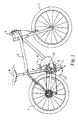
- the effort-saving bicycle of the present invention includes: a bicycle frame 6; a pair of wheels 7 pivotally disposed at a front end and a rear end of a lower side of the bicycle frame 6, respectively; a gear drive 2 pivotally disposed near a middle portion of the lower side of the bicycle frame 6; a handlebar 8 installed on a front end of an upper side of the bicycle frame 6; a saddle 9 installed near a middle portion of the upper side of the bicycle frame 6; a pair of drive cranks 11, each of which having a first end 111 and a second end 112, wherein the first end 111 is pivotally connected to a drive shaft 3 of the gear drive 2; and a pair of pedals, each of which pivotally connected to one of the second ends 112 of the pair of the drive cranks 11.
- each of the drive cranks 11 is designed in a bent fan-shape.
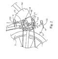
- An inner circumference and an outer circumference of the first end 111 thereof outwardly and radially bend a respective angle so as to extend to the second end 112 to form a bent portion 113, which is disposed between the first end 111 and the second end 112.
- the respective angle ⁇ is formed by bending the inner circumference and the respective angle ⁇ is formed by bending the outer circumference.
- the respective angle ⁇ is larger than the respective angle ⁇ .
- the bent portion 113 can enhance the strength of the drive cranks 11 such that the drive cranks 11 are not easily broken.
- the bent portion 113 is provided with a hole 12 at a pre-determined location thereof. By employing a bolt passing through the hole 12, each of the drive crank 11 is locked on the gear drive 2.
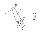
- Fig. 3 shows a torque generated on a moment arm by a force F exerted on the pedal 4.
- the force (denoted by F) exerted on each of the pedals 4 will act on the moment arm formed by the drive shaft 3 and the bolt 10.
- the force F acts on the location of the bolt 10 (or the hole 12) along the direction of force (see the dotted line of Fig. 2 ).
- a torque will be generated at the drive shaft 3.
- the force F exerted on each of the pedals 4 is transmitted to the bolt 10 to actuate the rotation of the gear drive 2 (or a front drive gear 5), thus pushing the bicycle to move forward.
- the motive power output by the bolt 10 directly actuates the rotation of the gear drive 2 (or the front drive gear 5) as a form of effort-saving leverage, which can lower the consumption of motive force and prevent the cyclist from getting tired, thus enhancing the efficiency of cycling.
- the advantages of the present invention are: (1) the bicycle becomes more effort-saving by lengthening effective moment arms to obtain more motive force; (2) the drive crank is designed in a bent fan-shape to enhance the strength thereof such that the drive crank is not easily broken; and (3) the drive rank is designed to have aesthetic appeal and much diversification such that the cyclist has more options and more funs.
Landscapes
- Engineering & Computer Science (AREA)
- Chemical & Material Sciences (AREA)
- Combustion & Propulsion (AREA)
- Transportation (AREA)
- Mechanical Engineering (AREA)
- Steering Devices For Bicycles And Motorcycles (AREA)
- Motorcycle And Bicycle Frame (AREA)
Applications Claiming Priority (1)
| Application Number | Priority Date | Filing Date | Title |
|---|---|---|---|
| CNU2006201497934U CN200977967Y (zh) | 2006-12-07 | 2006-12-07 | 省力脚踏车与传动曲柄 |
Publications (1)
| Publication Number | Publication Date |
|---|---|
| EP1930236A1 true EP1930236A1 (de) | 2008-06-11 |
Family
ID=37807851
Family Applications (1)
| Application Number | Title | Priority Date | Filing Date |
|---|---|---|---|
| EP07001663A Withdrawn EP1930236A1 (de) | 2006-12-07 | 2007-01-26 | Tretkurbeln und mit denselben ausgerüstetes Fahrrad |
Country Status (2)
| Country | Link |
|---|---|
| EP (1) | EP1930236A1 (de) |
| CN (1) | CN200977967Y (de) |
Citations (8)
| Publication number | Priority date | Publication date | Assignee | Title |
|---|---|---|---|---|
| FR739276A (fr) * | 1932-06-30 | 1933-01-09 | Manivelle pour cycles, vélos-moteurs, etc. | |
| FR976018A (fr) * | 1948-09-29 | 1951-03-13 | Manivelle courbe à deux branches | |
| FR1295063A (fr) * | 1961-06-27 | 1962-06-01 | Manivelle pour cycle et cyclomoteur | |
| WO1997002174A1 (en) * | 1995-07-06 | 1997-01-23 | Sang Yeon Jo | Crank-rods of a bicycle |
| FR2792602A1 (fr) * | 1999-04-23 | 2000-10-27 | Louis Dalery | Pedalier a developpement peripherique constant |
| WO2001081778A1 (en) * | 2000-04-07 | 2001-11-01 | Sang Yeon Jo | Eccentric crank rod |
| EP1442973A2 (de) * | 2003-01-29 | 2004-08-04 | NOVEK di PIERA TERRANEO CAPPELLETTI & C. S.n.c. | Tretkurbel für Fahrräder |
| US20060186630A1 (en) * | 2005-02-22 | 2006-08-24 | Chin-Chien Yuan | Effort-saving bicycle and transmission crank |
-
2006
- 2006-12-07 CN CNU2006201497934U patent/CN200977967Y/zh not_active Expired - Fee Related
-
2007
- 2007-01-26 EP EP07001663A patent/EP1930236A1/de not_active Withdrawn
Patent Citations (8)
| Publication number | Priority date | Publication date | Assignee | Title |
|---|---|---|---|---|
| FR739276A (fr) * | 1932-06-30 | 1933-01-09 | Manivelle pour cycles, vélos-moteurs, etc. | |
| FR976018A (fr) * | 1948-09-29 | 1951-03-13 | Manivelle courbe à deux branches | |
| FR1295063A (fr) * | 1961-06-27 | 1962-06-01 | Manivelle pour cycle et cyclomoteur | |
| WO1997002174A1 (en) * | 1995-07-06 | 1997-01-23 | Sang Yeon Jo | Crank-rods of a bicycle |
| FR2792602A1 (fr) * | 1999-04-23 | 2000-10-27 | Louis Dalery | Pedalier a developpement peripherique constant |
| WO2001081778A1 (en) * | 2000-04-07 | 2001-11-01 | Sang Yeon Jo | Eccentric crank rod |
| EP1442973A2 (de) * | 2003-01-29 | 2004-08-04 | NOVEK di PIERA TERRANEO CAPPELLETTI & C. S.n.c. | Tretkurbel für Fahrräder |
| US20060186630A1 (en) * | 2005-02-22 | 2006-08-24 | Chin-Chien Yuan | Effort-saving bicycle and transmission crank |
Also Published As
| Publication number | Publication date |
|---|---|
| CN200977967Y (zh) | 2007-11-21 |
Similar Documents
| Publication | Publication Date | Title |
|---|---|---|
| US20070228687A1 (en) | Bicycle propulsion mechanism | |
| US7784808B2 (en) | Rear-pedaling standing type bicycle structure | |
| US6688624B2 (en) | Foot pump scooter | |
| JP3530197B2 (ja) | 自転車用の改良されたペダル踏み機構 | |
| US6209900B1 (en) | Cycle provided with a moving fulcrum type leverage | |
| US10814933B2 (en) | Lever enhanced pedaling system with elevated crank sprockets | |
| US4147370A (en) | Front wheel drive for a bicycle | |
| KR20100057684A (ko) | 2개의 왕복 페달을 갖는 인력 차량 | |
| US8602434B2 (en) | Double chainring drivetrain | |
| US7717448B2 (en) | Ratchet-action drive mechanism for human power | |
| US6540244B1 (en) | Human-powered driving mechanism | |
| US7021639B2 (en) | Bicycle of type driven by operation of handle | |
| GB2493410A (en) | Auxiliary drive using rider's thighs to operate treadles | |
| AU2010201876A1 (en) | Linear drive bicycle with forward inclined prone driving position | |
| KR100902190B1 (ko) | 상하 왕복 구동장치를 구비한 자전거 | |
| EP1930236A1 (de) | Tretkurbeln und mit denselben ausgerüstetes Fahrrad | |
| US20160288871A1 (en) | Bicycle with front and rear drives with repositioned cranks, extended pedal levers drive | |
| KR100854586B1 (ko) | 왕복동식 페달을 가지는 자전거 | |
| US551667A (en) | Bicycle | |
| KR100968689B1 (ko) | 인력 구동형 동력전달장치 | |
| TWM281887U (en) | Easy-to-pedal bike and its transmission crank | |
| US6439591B1 (en) | Bicycle | |
| KR102237461B1 (ko) | 사용자의 상체 및 하체로 구동되는 전신 운동 자전거 | |
| AU2006246539B2 (en) | Levercycle | |
| KR101169139B1 (ko) | 인력 구동형 동력전달장치 |
Legal Events
| Date | Code | Title | Description |
|---|---|---|---|
| PUAI | Public reference made under article 153(3) epc to a published international application that has entered the european phase |
Free format text: ORIGINAL CODE: 0009012 |
|
| AK | Designated contracting states |
Kind code of ref document: A1 Designated state(s): AT BE BG CH CY CZ DE DK EE ES FI FR GB GR HU IE IS IT LI LT LU LV MC NL PL PT RO SE SI SK TR |
|
| AX | Request for extension of the european patent |
Extension state: AL BA HR MK RS |
|
| 17P | Request for examination filed |
Effective date: 20081025 |
|
| 17Q | First examination report despatched |
Effective date: 20081120 |
|
| AKX | Designation fees paid |
Designated state(s): AT BE BG CH CY CZ DE DK EE ES FI FR GB GR HU IE IS IT LI LT LU LV MC NL PL PT RO SE SI SK TR |
|
| STAA | Information on the status of an ep patent application or granted ep patent |
Free format text: STATUS: THE APPLICATION HAS BEEN WITHDRAWN |
|
| 18W | Application withdrawn |
Effective date: 20090718 |