EP1930286A2 - Turmkran mit automatischer Montage - Google Patents
Turmkran mit automatischer Montage Download PDFInfo
- Publication number
- EP1930286A2 EP1930286A2 EP07356155A EP07356155A EP1930286A2 EP 1930286 A2 EP1930286 A2 EP 1930286A2 EP 07356155 A EP07356155 A EP 07356155A EP 07356155 A EP07356155 A EP 07356155A EP 1930286 A2 EP1930286 A2 EP 1930286A2
- Authority
- EP
- European Patent Office
- Prior art keywords
- mast
- drum
- telescoping
- boom
- control shaft
- Prior art date
- Legal status (The legal status is an assumption and is not a legal conclusion. Google has not performed a legal analysis and makes no representation as to the accuracy of the status listed.)
- Granted
Links
- 230000037431 insertion Effects 0.000 claims abstract description 11
- 238000003780 insertion Methods 0.000 claims abstract description 11
- 238000004804 winding Methods 0.000 claims abstract description 5
- 230000005540 biological transmission Effects 0.000 claims description 13
- 239000004606 Fillers/Extenders Substances 0.000 claims 1
- 241001417494 Sciaenidae Species 0.000 description 2
- 241001080024 Telles Species 0.000 description 1
- 240000008042 Zea mays Species 0.000 description 1
- 230000000903 blocking effect Effects 0.000 description 1
- 230000000694 effects Effects 0.000 description 1
- 239000011435 rock Substances 0.000 description 1
- 238000001338 self-assembly Methods 0.000 description 1
- 238000004904 shortening Methods 0.000 description 1
Images


Classifications
-
- B—PERFORMING OPERATIONS; TRANSPORTING
- B66—HOISTING; LIFTING; HAULING
- B66C—CRANES; LOAD-ENGAGING ELEMENTS OR DEVICES FOR CRANES, CAPSTANS, WINCHES, OR TACKLES
- B66C23/00—Cranes comprising essentially a beam, boom, or triangular structure acting as a cantilever and mounted for translatory of swinging movements in vertical or horizontal planes or a combination of such movements, e.g. jib-cranes, derricks, tower cranes
- B66C23/18—Cranes comprising essentially a beam, boom, or triangular structure acting as a cantilever and mounted for translatory of swinging movements in vertical or horizontal planes or a combination of such movements, e.g. jib-cranes, derricks, tower cranes specially adapted for use in particular purposes
- B66C23/26—Cranes comprising essentially a beam, boom, or triangular structure acting as a cantilever and mounted for translatory of swinging movements in vertical or horizontal planes or a combination of such movements, e.g. jib-cranes, derricks, tower cranes specially adapted for use in particular purposes for use on building sites; constructed, e.g. with separable parts, to facilitate rapid assembly or dismantling, for operation at successively higher levels, for transport by road or rail
- B66C23/34—Self-erecting cranes, i.e. with hoisting gear adapted for crane erection purposes
- B66C23/342—Self-erecting cranes, i.e. with hoisting gear adapted for crane erection purposes with telescopic elements
-
- B—PERFORMING OPERATIONS; TRANSPORTING
- B66—HOISTING; LIFTING; HAULING
- B66C—CRANES; LOAD-ENGAGING ELEMENTS OR DEVICES FOR CRANES, CAPSTANS, WINCHES, OR TACKLES
- B66C23/00—Cranes comprising essentially a beam, boom, or triangular structure acting as a cantilever and mounted for translatory of swinging movements in vertical or horizontal planes or a combination of such movements, e.g. jib-cranes, derricks, tower cranes
- B66C23/18—Cranes comprising essentially a beam, boom, or triangular structure acting as a cantilever and mounted for translatory of swinging movements in vertical or horizontal planes or a combination of such movements, e.g. jib-cranes, derricks, tower cranes specially adapted for use in particular purposes
- B66C23/26—Cranes comprising essentially a beam, boom, or triangular structure acting as a cantilever and mounted for translatory of swinging movements in vertical or horizontal planes or a combination of such movements, e.g. jib-cranes, derricks, tower cranes specially adapted for use in particular purposes for use on building sites; constructed, e.g. with separable parts, to facilitate rapid assembly or dismantling, for operation at successively higher levels, for transport by road or rail
- B66C23/28—Cranes comprising essentially a beam, boom, or triangular structure acting as a cantilever and mounted for translatory of swinging movements in vertical or horizontal planes or a combination of such movements, e.g. jib-cranes, derricks, tower cranes specially adapted for use in particular purposes for use on building sites; constructed, e.g. with separable parts, to facilitate rapid assembly or dismantling, for operation at successively higher levels, for transport by road or rail constructed to operate at successively higher levels
- B66C23/283—Cranes comprising essentially a beam, boom, or triangular structure acting as a cantilever and mounted for translatory of swinging movements in vertical or horizontal planes or a combination of such movements, e.g. jib-cranes, derricks, tower cranes specially adapted for use in particular purposes for use on building sites; constructed, e.g. with separable parts, to facilitate rapid assembly or dismantling, for operation at successively higher levels, for transport by road or rail constructed to operate at successively higher levels with frameworks composed of assembled elements
Definitions
- the present invention relates to a self-erecting tower crane, this invention being more particularly concerned with such a crane with telescopic mast adapted to be raised by insertion of mast extensions.
- Self-erecting tower cranes of this type can be classified into two broad categories, depending on how to telescope the mast.
- a first category is that of cranes for which the telescoping of the mast is carried out with the crane boom folded vertically along the mast, to allow mounting of the crane in a small space, which may correspond to certain site conditions.
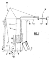
- a corresponding realization is illustrated, very schematically, on the figure 1 of the accompanying drawing, which shows an automated assembly tower crane, with its base frame 2, its mast 3, and its arrow 4.
- the mast 3, of telescopic structure comprises a lower mast element 5 mounted on the chassis of base 2 and an upper mast element 6, slidably mounted in the lower element, and this mast 3 can be raised by insertion of one or more extensions of the mast 7.
- the arrow 4 consists of successive arrow elements 8, 9 and 10, including two main boom elements 8 and 10 folding vertically along the mast 3, and an intermediate boom element 9, all these boom elements being hinged together, and the whole of the boom 4 being hinged to the top of the mast 3 around a horizontal axis.
- the telescoping of the mast 3 is achieved by means of a winch, with a telescoping drum 13 on which is wound a telescoping cable 14 which, by means of a haulage 15, raises the mast 3, that is to say the sliding of the upper mast element 6 relative to the mast element lower 5.
- this crane is equipped with a winch which comprises, in addition to the telescoping drum 13, a second coaxial drum said retaining drum 16, whose cable 17 is wound in the opposite direction of the cable 14 and has the role of unwinding the rear retaining cable 12 which extends it.
- the unwinding of the cables 12 and 17 is supposed to compensate exactly the elongation of the mast 3 during telescoping.
- a telescopic tie 18 connects the retaining cable 12 to the base frame 2, this pulling 18 lengthening during telescoping and shortening under the effect of its own weight, during the descent of the element of upper mast 6.
- the telescoping of the mast is carried out with the boom deployed horizontally.
- the upper mast member 6 is pushed upwards through the haulage 15, actuated by a telescoping winch, while unwinding the rear retaining cable 12 wound on the drum 16 of a retaining winch, so that the arrow remains substantially horizontal, as described in the patent French FR 2033482 (LOIRECORD ).
- the telescoping and retaining drums have suitable diameters so that, given the number of different strands of the respective hauls of the telescoping cable and the retaining cable, the mast telescopes while maintaining the horizontality of the arrow.
- An additional problem in obtaining a tower crane deployed the desired height is to raise the mast by inserting one or more mast extensions, which do not solve the aforementioned documents.
- the object of the present invention is to provide a self-erecting tower crane with a telescopic mast, which can be deployed according to one or the other of the two mounting configurations previously mentioned, to know with the boom folded along the mast or with the boom extended horizontally, and in which we can insert mast extensions in both mounting configurations.
- the invention relates to an automated assembly tower crane with a telescopic mast comprising a lower mast element mounted on a base frame and a top mast element to which is articulated an arrow, an arrow retainer with retaining cable connecting the boom to the rear portion of the base frame, the crane being provided for telescoping the mast with the arrow folded along the mast, or with the arrow in substantially horizontal position, a winch with telescoping drum being provided for winding a telescoping cable forming a haul, and a holding drum associated with the telescoping drum being provided for the simultaneous unwinding of the retaining cable,
- this crane being characterized in that the telescoping drum and the holding drum are mounted and motorized so that they can be rotated simultaneously for telescoping the mast or can be detached from one another for stop of the holding drum and a rotation drive of the single telescoping drum, for insertion of a mast extension at the base of the mast and support of the mast extension by the upper mast element or a previous mast extension.
- the telescoping drum and the holding drum are placed on the same control shaft connected to rotating drive means, the holding drum being secured to the control shaft. while the telescoping drum is mounted freely rotatable about this control shaft, means being provided for non-permanently rotating the telescoping drum with the control shaft, and this telescoping drum being adapted, when it is disengaged from the control shaft, to be linked to other rotating drive means.
- the rotational drive means linked to the control shaft, are advantageously constituted by a geared motor with brake, able to immobilize in rotation the control shaft and thus the holding drum, when the telescoping drum is coupled. to the other rotating drive means for supporting a mast extension.
- the means which make it possible to link the telescoping drum to the control shaft in a non-permanent manner are feasible as a dog clutch device.
- the rotational drive means to which the telescoping drum is adapted to be connected when it is disengaged from the control shaft, can be constituted by an auxiliary motor and by a transmission directly linking this auxiliary motor to the telescoping drum.
- this is a chain transmission, connecting the auxiliary motor to a toothed wheel carried by one of the flanges of the telescoping drum.
- the mast of the crane can be telescoped by winding the telescoping cable and the simultaneous unwinding of the retaining cable, the boom of the crane being folded back along the mast, be deployed horizontally.
- the retaining drum is immobilized in rotation, only the telescoping drum being rotated, the boom of the crane is held in position and it becomes possible to use the telescoping cable and its hauling for the support of a mast extension.
- the insertion of a mast extension and its support are compatible with the two configurations possible arrow when telescoping the mast.
- the insertion of a mast extension is performed using the carriage boom, which is positioned on the intermediate boom element in the case of mounting the crane with the boom folded along the mast, and which is positioned on the first main boom element in the case of a mounting crane with the boom extended horizontally.
- each mast extension 7 must first be brought into a planned opening at the base of the lower mast element 5, this operation being carried out using the boom carriage 19, positioned adequately on the arrow 4.
- the boom carriage 19 is positioned on the intermediate boom element 9 (see figure 1 ); in the case of an assembly carried out with the horizontal arrow 4, the boom carriage 19 is positioned on the first main boom element 8, also designated as an arrow foot.
- the mast telescoping system 3 including in particular the cable 14 and its haulage 15, is used to support the mast extension 7 introduced at the base of the mast 3, and to drive it upwards. to secure it with the upper mast element 6 (or with a similar mast extension previously inserted).
- the hoist mechanism of the crane designated as a whole by the reference 20, is designed according to the principle shown on the figure 3 .
- This mechanism 20 comprises a telescoping drum 13 and a retaining drum 16, arranged along the same axis.
- the telescoping cable is wound on the telescoping drum 13, while the retaining cable is wound on the holding drum 16.
- the telescoping drum 13 and the holding drum 16 are located on the same control shaft 21, coupled for its rotational drive to a geared motor 22 with brake.
- the holding drum 16 is permanently secured to the control shaft 21.
- the telescoping drum 13 is freely mounted to rotate around the control shaft 21, and a clutch device 23 is provided to rotate in a rotatable manner. non-permanent telescoping drum 13 with the control shaft 21.
- One of the flanges of the telescoping drum 13 carries a chain sprocket 24.
- An additional motor 25 is coupled to a chain gear 26, which can be linked in motion by a transmission chain 27 to the toothed gear 24.
- telescoping drum 13 One of the flanges of the telescoping drum 13 carries a chain sprocket 24.
- An additional motor 25 is coupled to a chain gear 26, which can be linked in motion by a transmission chain 27 to the toothed gear 24.
- the telescoping drum 13 is clutched on the control shaft 21, and thus the two drums, telescoping respectively 13 and retaining 16, are driven in rotation simultaneously by the geared motor 22.
- the boom 4 is held in position (either folded along the mast 3 or horizontal) by blocking the retaining device.
- arrow 11 with the brake of the geared motor 22, which immobilizes in rotation the holding drum 16.
- the telescoping drum 13 is then disengaged from the control shaft 21, by action on the clutch device 23, then this telescoping drum 13 is connected to the motor 25 by means of the two toothed wheels 24 and 26 and the transmission chain 27 passing on these two wheels.
- the motor 25 is then actuated to rotate the telescoping drum 13 by rotating it around the control shaft 21 immobilized in rotation. Actuation of the motor 25 and the telescoping drum 13 first causes the telescoping haulage 15 to descend to the base of the mast 3 to take over the mast extension 7 previously brought into the waiting position at this position. in law. Then, by reversing the direction of rotation of the motor 25, thus of the telescoping drum 13, the mast extension 7 is pushed upwards, until it comes against the base of the upper mast element 6. The top of the mast extension 7 is then secured, by broaching, with the base of the upper mast element 6.
- the telescoping of the mast 3 is resumed, that is to say that the previously constituted assembly, formed by the upper mast element 6 and the mast extension 7, is moved upwards, using simultaneously the two drums 13 and 16, the telescoping drum 13 having been secured in rotation with the control shaft 21.
Landscapes
- Engineering & Computer Science (AREA)
- Structural Engineering (AREA)
- Transportation (AREA)
- Mechanical Engineering (AREA)
- Jib Cranes (AREA)
Applications Claiming Priority (1)
| Application Number | Priority Date | Filing Date | Title |
|---|---|---|---|
| FR0610674A FR2909651B1 (fr) | 2006-12-07 | 2006-12-07 | Grue a tour a montage automatise |
Publications (3)
| Publication Number | Publication Date |
|---|---|
| EP1930286A2 true EP1930286A2 (de) | 2008-06-11 |
| EP1930286A3 EP1930286A3 (de) | 2008-07-02 |
| EP1930286B1 EP1930286B1 (de) | 2010-01-27 |
Family
ID=38051366
Family Applications (1)
| Application Number | Title | Priority Date | Filing Date |
|---|---|---|---|
| EP20070356155 Active EP1930286B1 (de) | 2006-12-07 | 2007-10-30 | Turmkran mit automatischer Montage |
Country Status (4)
| Country | Link |
|---|---|
| EP (1) | EP1930286B1 (de) |
| DE (1) | DE602007004556D1 (de) |
| ES (1) | ES2340333T3 (de) |
| FR (1) | FR2909651B1 (de) |
Cited By (1)
| Publication number | Priority date | Publication date | Assignee | Title |
|---|---|---|---|---|
| CN102602821A (zh) * | 2012-03-28 | 2012-07-25 | 山东润科机电设备有限公司 | 一种安全重载塔吊 |
Citations (2)
| Publication number | Priority date | Publication date | Assignee | Title |
|---|---|---|---|---|
| FR2033482A5 (de) | 1969-02-21 | 1970-12-04 | Loirecord | |
| FR2183594A1 (de) | 1972-05-12 | 1973-12-21 | Rock |
Family Cites Families (2)
| Publication number | Priority date | Publication date | Assignee | Title |
|---|---|---|---|---|
| FR1403907A (fr) * | 1964-05-11 | 1965-06-25 | Richier Sa | Grue |
| DE2263157C2 (de) * | 1972-12-22 | 1974-05-16 | Fa. Wilhelm Reich, 7900 Ulm | Kran, insbesondere Laufkatzen-Auslegerturmkran |
-
2006
- 2006-12-07 FR FR0610674A patent/FR2909651B1/fr active Active
-
2007
- 2007-10-30 EP EP20070356155 patent/EP1930286B1/de active Active
- 2007-10-30 ES ES07356155T patent/ES2340333T3/es active Active
- 2007-10-30 DE DE200760004556 patent/DE602007004556D1/de active Active
Patent Citations (2)
| Publication number | Priority date | Publication date | Assignee | Title |
|---|---|---|---|---|
| FR2033482A5 (de) | 1969-02-21 | 1970-12-04 | Loirecord | |
| FR2183594A1 (de) | 1972-05-12 | 1973-12-21 | Rock |
Cited By (1)
| Publication number | Priority date | Publication date | Assignee | Title |
|---|---|---|---|---|
| CN102602821A (zh) * | 2012-03-28 | 2012-07-25 | 山东润科机电设备有限公司 | 一种安全重载塔吊 |
Also Published As
| Publication number | Publication date |
|---|---|
| ES2340333T3 (es) | 2010-06-01 |
| EP1930286A3 (de) | 2008-07-02 |
| FR2909651B1 (fr) | 2009-01-16 |
| DE602007004556D1 (de) | 2010-03-18 |
| FR2909651A1 (fr) | 2008-06-13 |
| EP1930286B1 (de) | 2010-01-27 |
Similar Documents
| Publication | Publication Date | Title |
|---|---|---|
| EP2409943B1 (de) | Teleskop-Hubvorrichtung mit Zahnrad- und Zahngestänge-Antrieb | |
| FR2549029A1 (fr) | Elevateur comportant au moins un mat telescopique | |
| FR2756551A1 (fr) | Procede et dispositif pour le montage des tirants des fleches de grues a tour | |
| EP1930286B1 (de) | Turmkran mit automatischer Montage | |
| EP0360702B1 (de) | Zusammenlegbarer Kran mit einem Ausleger, bestehend aus zwei oder drei gelenkig miteinander verbundenen Elementen | |
| EP2572695B1 (de) | Hebestuhl | |
| EP1619078B1 (de) | Rollo für Laderaumabdeckung für ein Kraftfahrzeug und hiermit ausgestattetes Fahrzeug | |
| FR2636616A1 (fr) | Grue repliable a fleche en deux ou trois elements articules les uns aux autres | |
| EP1927570B1 (de) | Kranmast mit Gegengewicht | |
| EP3347668B1 (de) | Vorrichtung zum transportieren eines torpedos von einem transportwagen zu einem abschussrohr | |
| EP2213609B1 (de) | Faltbare Ausleger für Turmdrehkran | |
| FR2761971A1 (fr) | Grue a montage automatise a fleche pliable, avec repliage lateral pour transport | |
| EP0473518A1 (de) | Selbstaufstellender Kran mit seitlich klappbarem Ausleger | |
| FR2867497A1 (fr) | Dispositif d'aide au decoffrage | |
| FR2955135A1 (fr) | Mat articule extensible a charniere demontable | |
| FR2930536A1 (fr) | Potence mobile de chantier | |
| BE1023694B1 (fr) | Methode et systeme de maintenance pour recepteur solaire | |
| EP1057776B1 (de) | Kran mit aus Gliedern bestehendem Kranarm | |
| EP1419100B1 (de) | Motorangetriebene winde | |
| FR2845826A1 (fr) | Bras-support d'antenne de radiocommande pour appareil de levage | |
| EP4321702B1 (de) | Sonnen- oder wetterschutzanlage | |
| EP1790785A1 (de) | Shelter comprising at least two telescopic covering modules | |
| FR3025773A1 (fr) | Remorque avec plateforme de chargement abaissable et interchangeable | |
| WO2011144734A1 (fr) | Machine, notamment engin de chantier, avec système escamotable de protection anti-chute d'un opérateur montant sur le bâti de la machine | |
| MC200134A1 (fr) | Machine, notamment engin de chantier, avec systèmeescamotable de protection anti-chute d'un opérate ur montant sur le bâti. |
Legal Events
| Date | Code | Title | Description |
|---|---|---|---|
| PUAI | Public reference made under article 153(3) epc to a published international application that has entered the european phase |
Free format text: ORIGINAL CODE: 0009012 |
|
| PUAL | Search report despatched |
Free format text: ORIGINAL CODE: 0009013 |
|
| AK | Designated contracting states |
Kind code of ref document: A2 Designated state(s): AT BE BG CH CY CZ DE DK EE ES FI FR GB GR HU IE IS IT LI LT LU LV MC MT NL PL PT RO SE SI SK TR |
|
| AX | Request for extension of the european patent |
Extension state: AL BA HR MK RS |
|
| AK | Designated contracting states |
Kind code of ref document: A3 Designated state(s): AT BE BG CH CY CZ DE DK EE ES FI FR GB GR HU IE IS IT LI LT LU LV MC MT NL PL PT RO SE SI SK TR |
|
| AX | Request for extension of the european patent |
Extension state: AL BA HR MK RS |
|
| AKX | Designation fees paid | ||
| 17P | Request for examination filed |
Effective date: 20090213 |
|
| RBV | Designated contracting states (corrected) |
Designated state(s): DE ES IT |
|
| REG | Reference to a national code |
Ref country code: DE Ref legal event code: 8566 |
|
| GRAP | Despatch of communication of intention to grant a patent |
Free format text: ORIGINAL CODE: EPIDOSNIGR1 |
|
| GRAS | Grant fee paid |
Free format text: ORIGINAL CODE: EPIDOSNIGR3 |
|
| GRAA | (expected) grant |
Free format text: ORIGINAL CODE: 0009210 |
|
| AK | Designated contracting states |
Kind code of ref document: B1 Designated state(s): DE ES IT |
|
| REF | Corresponds to: |
Ref document number: 602007004556 Country of ref document: DE Date of ref document: 20100318 Kind code of ref document: P |
|
| REG | Reference to a national code |
Ref country code: ES Ref legal event code: FG2A Ref document number: 2340333 Country of ref document: ES Kind code of ref document: T3 |
|
| PLBE | No opposition filed within time limit |
Free format text: ORIGINAL CODE: 0009261 |
|
| STAA | Information on the status of an ep patent application or granted ep patent |
Free format text: STATUS: NO OPPOSITION FILED WITHIN TIME LIMIT |
|
| 26N | No opposition filed |
Effective date: 20101028 |
|
| PG25 | Lapsed in a contracting state [announced via postgrant information from national office to epo] |
Ref country code: IT Free format text: LAPSE BECAUSE OF NON-PAYMENT OF DUE FEES Effective date: 20101030 |
|
| PGFP | Annual fee paid to national office [announced via postgrant information from national office to epo] |
Ref country code: DE Payment date: 20241021 Year of fee payment: 18 |
|
| PGFP | Annual fee paid to national office [announced via postgrant information from national office to epo] |
Ref country code: IT Payment date: 20241025 Year of fee payment: 18 Ref country code: ES Payment date: 20241127 Year of fee payment: 18 |