EP1930449A2 - Schachtofen - Google Patents
Schachtofen Download PDFInfo
- Publication number
- EP1930449A2 EP1930449A2 EP07023877A EP07023877A EP1930449A2 EP 1930449 A2 EP1930449 A2 EP 1930449A2 EP 07023877 A EP07023877 A EP 07023877A EP 07023877 A EP07023877 A EP 07023877A EP 1930449 A2 EP1930449 A2 EP 1930449A2
- Authority
- EP
- European Patent Office
- Prior art keywords
- shaft furnace
- burden
- cooling gas
- cooling
- zone
- Prior art date
- Legal status (The legal status is an assumption and is not a legal conclusion. Google has not performed a legal analysis and makes no representation as to the accuracy of the status listed.)
- Granted
Links
Images

Classifications
-
- C—CHEMISTRY; METALLURGY
- C21—METALLURGY OF IRON
- C21B—MANUFACTURE OF IRON OR STEEL
- C21B13/00—Making spongy iron or liquid steel, by direct processes
- C21B13/02—Making spongy iron or liquid steel, by direct processes in shaft furnaces
-
- F—MECHANICAL ENGINEERING; LIGHTING; HEATING; WEAPONS; BLASTING
- F27—FURNACES; KILNS; OVENS; RETORTS
- F27B—FURNACES, KILNS, OVENS OR RETORTS IN GENERAL; OPEN SINTERING OR LIKE APPARATUS
- F27B1/00—Shaft or like vertical or substantially vertical furnaces
- F27B1/005—Shaft or like vertical or substantially vertical furnaces wherein no smelting of the charge occurs, e.g. calcining or sintering furnaces
-
- F—MECHANICAL ENGINEERING; LIGHTING; HEATING; WEAPONS; BLASTING
- F27—FURNACES; KILNS; OVENS; RETORTS
- F27B—FURNACES, KILNS, OVENS OR RETORTS IN GENERAL; OPEN SINTERING OR LIKE APPARATUS
- F27B1/00—Shaft or like vertical or substantially vertical furnaces
- F27B1/10—Details, accessories or equipment specially adapted for furnaces of these types
- F27B1/16—Arrangements of tuyeres
-
- F—MECHANICAL ENGINEERING; LIGHTING; HEATING; WEAPONS; BLASTING
- F27—FURNACES; KILNS; OVENS; RETORTS
- F27B—FURNACES, KILNS, OVENS OR RETORTS IN GENERAL; OPEN SINTERING OR LIKE APPARATUS
- F27B1/00—Shaft or like vertical or substantially vertical furnaces
- F27B1/10—Details, accessories or equipment specially adapted for furnaces of these types
- F27B1/18—Arrangements of dust collectors
-
- F—MECHANICAL ENGINEERING; LIGHTING; HEATING; WEAPONS; BLASTING
- F27—FURNACES; KILNS; OVENS; RETORTS
- F27D—DETAILS OR ACCESSORIES OF FURNACES, KILNS, OVENS OR RETORTS, IN SO FAR AS THEY ARE OF KINDS OCCURRING IN MORE THAN ONE KIND OF FURNACE
- F27D17/00—Arrangements for using waste heat; Arrangements for using, or disposing of, waste gases
- F27D17/30—Arrangements for extraction or collection of waste gases; Hoods therefor
Definitions
- the present invention relates to a vertical shaft furnace for a burden moving under the influence of gravitation from the top to the bottom of the shaft furnace, in particular for the production of directly reduced iron, with a hot reduction zone and a cooling zone following the reduction zone, in which feed openings for a cooling gas are provided, and with a cooling gas collecting member which is provided in a transition portion between the reduction zone and the cooling zone.
- US 4,054,444 discloses such a shaft furnace.
- a feed opening for the burden and furnace gas outlet are provided at the top of the shaft furnace.
- a burden of iron oxide material may be fed into the shaft furnace through the feed opening.
- the furnace gas outlet serves for discharging used furnace gas.
- the feed opening forms the upper end of a reduction zone, in which gas bustle ports are provided in order to introduce reduction gas, which contains carbon monoxide and hydrocarbon and is produced in a reformer.
- Reduction gas reduces the iron oxide at high temperatures directly into iron.
- the reduction zone is followed by a transition zone where hot material passes to a cooling zone with minimum changes in the chemistry of the product.
- the cooling gas collecting chamber is for receiving hot cooling gas, which has passed through the hot DRI material cooling zone, and recycling it through the cooling gas scrubber to the cooling zone of the furnace. In this way the DRI is cooled, prior to discharge through the bottom of the shaft furnace discharge feeder.
- a cooling gas collecting member is, however, provided in the central part of the shaft furnace. In this way on both sides narrow portions remain in the transition region from the reduction zone to the cooling zone, through which cooling gas may pass into the reduction zone, because no measures are taken to prevent this. As a result the entry of cooling gas into the reduction zone is not effectively prevented, which leads to an undesired cooling of the burden in this zone. In this way more thermal energy has to be fed to the reduction zone in order to maintain the reduction reaction.
- the cooling gas collecting member comprises collector arms arranged in cross shape, each of which forms a cooling gas off-take.
- collector arms arranged in cross-shape a transition from cooling gas from the cooling zone into the reduction zone is prevented. Accordingly there is no undesired cooling effect in the reduction zone, so that the efficiency of the shaft furnace is improved.
- the cooling gas off-takes have a cross sectional area increasing beginning from the crossing point towards the exterior side.
- the collector arms are slanted from the horizontal in the flow direction of the burden.
- the collector arms may be slanted in an angle between 5 to 10° from the horizontal direction. In this way the collector arms offer a reduced resistance to the flowing burden.
- the collector arms each have an edge for breaking the burden, which is oriented against the flow direction of the burden. In this way the burden may even more easy pass by the cooling gas collecting member.
- collector arms may be connected to each other at their outer edge portions. In this way an additional stability of the cooling gas collecting elements is obtained.
- the cooling gas collecting member comprises at least one cone, wherein the cone tip is oriented opposite to the flow direction of the burden.
- a cone breaks the burden in the direction of the shaft furnace side walls.
- the shaft furnace may furthermore comprise at least one gas pipe which is provided to discharge a hydrocarbon gas into the cone. In this way the cone is cooled, so that its durability is improved.
- An upper cone may be provided relative to the flow direction of the burden before the connector arms. By means of this upper cone the burden is easily passed by the crossing portion of the connector arms.
- the shaft furnace may also comprise a lower cone, which in relation to the flow direction of the burden is arranged behind the connector arms.
- This lower cone may be arranged directly at the base face of the upper cone between the collector arms. The lower cone supports the uniform flow of the burden.
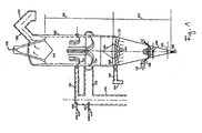
- Figure 1 shows a shaft furnace 100 according to the present invention in schematic view, which is in particular adapted for the production of directly reduced iron.
- the shaft furnace 100 has a generally cylindrical form and is vertically arranged.
- a furnace exit gas outlet 120 is provided at the top of the shaft furnace 100, the central axis of the shaft furnace outlet 120 being inclined with regard to the horizontal axis of the shaft furnace 100 by an angle of 45 to 55°.
- the furnace gas outlet 120 is connected with a furnace gas main pipe 123 in such a way, that the central axis of the furnace gas outlet 120 and of the furnace gas main pipe 123 turn at an angle of 90°.
- a feed opening 109 for a burden 115 of iron oxide material is provided at the top of the shaft furnace 100.
- the shaft furnace 100 is designed in such a way, that the burden 115 will move under the influence of gravity from the top to the bottom of the shaft furnace downwardly through the interior of the shaft furnace 100.
- the interior of the shaft furnace 100 is devided into a reduction zone 101, the upper end of which forms the feed opening 109, and a cooling zone 103, which is arranged immediately underneath the reduction zone 101.
- a discharge opening 190 is provided, through which the reduced iron may be discharged from the shaft furnace 100.
- the shaft furnace 100 comprises a reducing gas feeding device 130, which is connected with two bustle gas lines 131, 132 with two sets of bustle gas ports 133, 134.
- the bustle gas ports 133, 134 are arranged at two vertically different levels on the periphery of the shaft furnace wall.
- Both bustle gas lines 131, 132 are equipped with an injection system 400, 410 for a gas mixture.
- the two injection systems 400 410 are each connected with a hydrocarbon source 401, 415 and an oxygen source 402, wherein the two hydrocarbon sources 401, 415 may differ from one another.
- Both injection systems 400, 410 are designed in such a way, that the amount of hydrocarbon and oxygen may be regulated separately.
- FIG. 2 shows an enlarged side view of the injection system 400.
- the injection system 400 comprises two lines 403, 404, wherein the line 403 is connected with the hydrocarbon source 401 and the line 404 is connected with the oxygen source 402.
- the line 403 runs coaxially within the line 404, and both lines are connected to a mixing portion 405.
- the mixing portion 405 has a discharge opening 406 for the hydrocarbon-oxygen-mixture.
- cooling gas nozzles 166 are provided on the shell, which are connected with a cooling gas inlet header 165.
- a cooling gas collecting member 160 is provided in the lower part of a transition zone between the reduction zone 101 and the cooling zone 103.
- the cooling gas collecting member 160 is shown in figures 3 and 4 in an enlarged scale. It comprises invertedly tapered channels formed in collector arms 181, 182, 183, 184 arranged in a cross shape, each of which forms a cooling gas off-take 170, 171, 172, 173.
- the lower side of the collector arms 181, 182, 183, 184 opposite to the shaft furnace bottom have suction openings for the cooling gas formed therein.
- the cross sectional area of the cooling gas off-takes 170, 171, 172, 173 increases beginning from the crossing point towards the exterior side.
- collector arms 181, 182, 183, 184 are inclined with an angle between 5 and 10° from the horizontal direction in the direction of the shaft furnace shell.
- the collector arms 182, 183 and 183, 184 and 181, 184 are connected at their outer edge portions to each other, so that all collector arms 181, 182, 183, 184 form a common off-take header.
- the off-take header is connected with an outlet 164, in which a suction device may be provided.
- the cooling gas collecting number 160 is further provided with an upper hollow cone 161, which is provided above the collector arms 181, 182, 183, 184 in the center thereof (see fig. 4 ).
- the upper cone 161 is hollow.
- a lower cone 162 is provided, which in relation of the flow direction of the burden 115 is positioned behind (beneath) the collector arms 181, 182, 183, 184 in the center thereof.
- a gas pipe 151 is connected to the hollow interior of the upper cone 161 and is connected to hydrocarbon source which is not shown in the drawing.
- rotating shafts 180, 185 are provided for breaking and grinding clusters, if present.
- the burden 115 of iron oxide material is fed through the feed opening 109, into the reduction zone 101.
- a hot reduction gas of hydrogen and carbon monoxide is blown into the reduction zone 101 through the bustle gas ports 133, 134 in such a way, that it flows in the opposite direction of the burden 115, which flows downwardly under the influence of gravity.
- the reduction gas reduces the iron oxide at high temperature and in direct contact with the iron.
- the reacted reduction gas then reaches the shaft furnace top, where it enters the furnace gas outlet 120. Due to the inclination of the furnace gas outlet 120 only a small amount of dust particles reaches the furnace gas main pipe 123, because gravity restrains the dust particles.
- the reduced burden 115 descends from the reduction zone 101 into the cooling zone 103. On its way it passes the cooling gas collecting member 160, thereby passing between the collector arms 181, 182, 183, 184, which offer a comparatively small resistance. At the same time the burden 115 is loosened by the top cone 161 in the direction of the shaft furnace wall. The top cone 161 is cooled by the gas entering into the interior thereof.
- a cooling gas is blown in by way of the cooling gas ports 166.
- the cooling gas streams upwardly against the descending burden 115 thereby cooling the burden 115.
- hot gas reaches the collector arms 181, 182, 183, 184 and exits through the suction openings thereof into the cooling gas off-takes 171, 172, 173, 174.
- the cooling gas is then passed to the cooling gas offtake header 164 through the cooling gas off-takes 171, 172, 173, 174 and is thus effectively removed from the shaft furnace 100 at the lower limit of the cooling zone 103. In this way, the cooling gas is effectively prevented from entering into the reduction zone 101.
- the cooled-off burden 115 finally discharges through the discharge port 190 from the shaft furnace 100.
Landscapes
- Engineering & Computer Science (AREA)
- Mechanical Engineering (AREA)
- General Engineering & Computer Science (AREA)
- Chemical & Material Sciences (AREA)
- Materials Engineering (AREA)
- Manufacturing & Machinery (AREA)
- Environmental & Geological Engineering (AREA)
- Metallurgy (AREA)
- Organic Chemistry (AREA)
- Manufacture Of Iron (AREA)
- Vertical, Hearth, Or Arc Furnaces (AREA)
- Waste-Gas Treatment And Other Accessory Devices For Furnaces (AREA)
- Heat Treatment Of Articles (AREA)
- Compressor (AREA)
Applications Claiming Priority (2)
| Application Number | Priority Date | Filing Date | Title |
|---|---|---|---|
| IR138538200 | 2006-12-11 | ||
| DE102006062689A DE102006062689B4 (de) | 2006-12-21 | 2006-12-21 | Schachtofen für die direkte Reduktion von Eisenoxid |
Publications (3)
| Publication Number | Publication Date |
|---|---|
| EP1930449A2 true EP1930449A2 (de) | 2008-06-11 |
| EP1930449A3 EP1930449A3 (de) | 2009-01-07 |
| EP1930449B1 EP1930449B1 (de) | 2012-06-27 |
Family
ID=83229110
Family Applications (3)
| Application Number | Title | Priority Date | Filing Date |
|---|---|---|---|
| EP07023876A Active EP1930678B1 (de) | 2006-12-11 | 2007-12-10 | Schachtofen |
| EP07023877A Active EP1930449B1 (de) | 2006-12-11 | 2007-12-10 | Schachtofen |
| EP07023875A Active EP1930448B1 (de) | 2006-12-11 | 2007-12-10 | Schachtofen |
Family Applications Before (1)
| Application Number | Title | Priority Date | Filing Date |
|---|---|---|---|
| EP07023876A Active EP1930678B1 (de) | 2006-12-11 | 2007-12-10 | Schachtofen |
Family Applications After (1)
| Application Number | Title | Priority Date | Filing Date |
|---|---|---|---|
| EP07023875A Active EP1930448B1 (de) | 2006-12-11 | 2007-12-10 | Schachtofen |
Country Status (4)
| Country | Link |
|---|---|
| EP (3) | EP1930678B1 (de) |
| AT (1) | ATE473302T1 (de) |
| DE (4) | DE202007019452U1 (de) |
| ES (3) | ES2386466T3 (de) |
Families Citing this family (5)
| Publication number | Priority date | Publication date | Assignee | Title |
|---|---|---|---|---|
| CN101556108B (zh) * | 2009-05-25 | 2010-12-01 | 四川大学 | 竖窑与竖窑法制磷酸的工艺 |
| WO2018085514A1 (en) * | 2016-11-03 | 2018-05-11 | Midrex Technologies, Inc. | Direct reduction process and shaft furnace utilizing an extended flow diverter cone |
| CN109182634B (zh) * | 2018-09-20 | 2023-08-15 | 中晋冶金科技有限公司 | 一种高效的气基竖炉直接还原炼铁系统及方法 |
| US12084730B2 (en) | 2020-03-24 | 2024-09-10 | Midrex Technologies, Inc. | Methods and systems for increasing the carbon content of direct reduced iron in a reduction furnace |
| CN116769994B (zh) * | 2023-08-25 | 2023-11-17 | 山西冶金工程技术有限公司 | 一种气基还原竖炉松料装置 |
Citations (1)
| Publication number | Priority date | Publication date | Assignee | Title |
|---|---|---|---|---|
| US4054444A (en) | 1975-09-22 | 1977-10-18 | Midrex Corporation | Method for controlling the carbon content of directly reduced iron |
Family Cites Families (13)
| Publication number | Priority date | Publication date | Assignee | Title |
|---|---|---|---|---|
| CA874354A (en) * | 1971-06-29 | Huttenwerk Oberhausen Ag | Furnace for direct reduction of iron ores | |
| DE1458762A1 (de) * | 1965-07-29 | 1969-03-13 | Huettenwerk Oberhausen Ag | Schachtofen fuer die Direktreduktion von Eisenerz |
| CA922519A (en) * | 1968-06-24 | 1973-03-13 | Midland-Ross Corporation | Method of and apparatus for reducing iron oxide to metallic iron |
| AU459472B2 (en) * | 1971-03-29 | 1975-03-11 | Nippon Koran Kabushiki Kaisha | A combustion process and apparatus for blast furnaces |
| AT342632B (de) * | 1973-11-06 | 1978-04-10 | Bischoff Gasreinigung | Gichtgasreinigungsanlage fur druckhochofen |
| JPS5814485B2 (ja) * | 1975-08-29 | 1983-03-19 | イシカワジマハリマジユウコウギヨウ カブシキガイシヤ | ヨウコウロ |
| JPS5260204A (en) * | 1975-11-13 | 1977-05-18 | Ishikawajima Harima Heavy Ind Co Ltd | Dust remover for blast furnace |
| JPS5832205B2 (ja) * | 1976-01-09 | 1983-07-12 | 石川島播磨重工業株式会社 | 高炉のガス捕集装置 |
| GB2016124B (en) * | 1978-03-11 | 1982-06-09 | Hamburger Stahlwerke Gmbh | Rocess and apparatus for the direct reduction of iron ores |
| US4536213A (en) * | 1984-09-10 | 1985-08-20 | Mildrex International, B.V. | Reforming of higher hydrocarbons for metal oxide reduction |
| FR2702221B1 (fr) * | 1993-03-03 | 1995-04-28 | Air Liquide | Procédé d'obtention de métal au haut-fourneau ou au cubilot. |
| US20020007699A1 (en) | 1997-09-05 | 2002-01-24 | Montague Stephen C. | Apparatus and method for optimizing the use of oxygen in the direct reduction of iron |
| IT1302815B1 (it) * | 1998-12-11 | 2000-09-29 | Danieli & C Ohg Sp | Procedimento ed apparato per la riduzione diretta di minerale diferro con iniezione ottimizzata del gas riducente |
-
2007
- 2007-12-10 DE DE202007019452U patent/DE202007019452U1/de not_active Expired - Lifetime
- 2007-12-10 ES ES07023877T patent/ES2386466T3/es active Active
- 2007-12-10 DE DE602007007561T patent/DE602007007561D1/de active Active
- 2007-12-10 ES ES07023875T patent/ES2346796T3/es active Active
- 2007-12-10 EP EP07023876A patent/EP1930678B1/de active Active
- 2007-12-10 DE DE202007019472U patent/DE202007019472U1/de not_active Expired - Lifetime
- 2007-12-10 ES ES07023876T patent/ES2386464T3/es active Active
- 2007-12-10 AT AT07023875T patent/ATE473302T1/de active
- 2007-12-10 EP EP07023877A patent/EP1930449B1/de active Active
- 2007-12-10 DE DE202007019169U patent/DE202007019169U1/de not_active Expired - Lifetime
- 2007-12-10 EP EP07023875A patent/EP1930448B1/de active Active
Patent Citations (1)
| Publication number | Priority date | Publication date | Assignee | Title |
|---|---|---|---|---|
| US4054444A (en) | 1975-09-22 | 1977-10-18 | Midrex Corporation | Method for controlling the carbon content of directly reduced iron |
Also Published As
| Publication number | Publication date |
|---|---|
| ES2386464T3 (es) | 2012-08-21 |
| EP1930678A2 (de) | 2008-06-11 |
| DE202007019169U1 (de) | 2010-11-11 |
| EP1930678A3 (de) | 2008-12-31 |
| DE602007007561D1 (de) | 2010-08-19 |
| EP1930448A2 (de) | 2008-06-11 |
| EP1930678B1 (de) | 2012-06-27 |
| ES2346796T3 (es) | 2010-10-20 |
| EP1930449B1 (de) | 2012-06-27 |
| ATE473302T1 (de) | 2010-07-15 |
| DE202007019452U1 (de) | 2012-08-27 |
| EP1930448A3 (de) | 2008-12-31 |
| DE202007019472U1 (de) | 2012-10-12 |
| ES2386466T3 (es) | 2012-08-21 |
| EP1930449A3 (de) | 2009-01-07 |
| EP1930448B1 (de) | 2010-07-07 |
Similar Documents
| Publication | Publication Date | Title |
|---|---|---|
| US9273368B2 (en) | Process for direct reduction of iron oxide | |
| EP1930449B1 (de) | Schachtofen | |
| AU2019201093B2 (en) | Smelting Process and Apparatus | |
| CN103189528B (zh) | 用来控制悬浮熔炼炉的热平衡的方法和悬浮熔炼炉 | |
| RU2013140830A (ru) | Усовершенствованные плазменные газификаторы для производства сингаза | |
| CN116235014B (zh) | 竖井炉和用于竖井炉的工艺气体喷射器 | |
| KR101661010B1 (ko) | 서스펜션 제련로 또는 서스펜션 전로에서 정광 버너의 분말 고형재 공급을 균일화하는 장치 | |
| NL8201945A (nl) | Werkwijze en inrichting voor de vervaardiging van vloeibaar ijzer uit oxydisch ijzererts. | |
| CN101855506B (zh) | 用于在熔化气化器中制造和熔化液态的生铁或者液态的钢半成品的方法 | |
| CN101688259A (zh) | 用于制备海绵铁的方法和装置 | |
| US9400138B2 (en) | Melting reduction assembly and method for operating a melting reduction assembly | |
| US6454833B1 (en) | Process for producing liquid pig iron or semifinished steel products from iron-containing materials | |
| US10845123B2 (en) | Raw material supply device, flash smelting furnace and nozzle member | |
| US20100199560A1 (en) | Plasma gasification reactor | |
| US6224647B1 (en) | Process and device for charging a fusion gasifier with gasifying means and spongy iron | |
| SK283453B6 (sk) | Taviaci generátor na výrobu roztaveného kovu a zariadenie na výrobu roztaveného kovu obsahujúce taký taviaci generátor | |
| CN102725382A (zh) | 气化反应器和方法 | |
| CN203269965U (zh) | 立式竖炉 | |
| CN211620426U (zh) | 气流床粉煤气化装置 | |
| CN120176431A (zh) | 闪速冶炼装置和闪速冶炼方法 | |
| CN120641715A (zh) | 顺流-逆流蓄热式竖窑和碳酸盐岩的燃烧方法 | |
| BRPI0611894B1 (pt) | Processo e usina para produzir ferro a partir de um material que contém ferro | |
| CN105107435B (zh) | 一种流化反应器及使用该反应器处理矿石的方法 | |
| WO2026027108A1 (en) | Reactor for gas-based pressurised counter current shaft furnace direct reduction |
Legal Events
| Date | Code | Title | Description |
|---|---|---|---|
| PUAI | Public reference made under article 153(3) epc to a published international application that has entered the european phase |
Free format text: ORIGINAL CODE: 0009012 |
|
| AK | Designated contracting states |
Kind code of ref document: A2 Designated state(s): AT BE BG CH CY CZ DE DK EE ES FI FR GB GR HU IE IS IT LI LT LU LV MC MT NL PL PT RO SE SI SK TR |
|
| AX | Request for extension of the european patent |
Extension state: AL BA HR MK RS |
|
| PUAL | Search report despatched |
Free format text: ORIGINAL CODE: 0009013 |
|
| AK | Designated contracting states |
Kind code of ref document: A3 Designated state(s): AT BE BG CH CY CZ DE DK EE ES FI FR GB GR HU IE IS IT LI LT LU LV MC MT NL PL PT RO SE SI SK TR |
|
| AX | Request for extension of the european patent |
Extension state: AL BA HR MK RS |
|
| AKX | Designation fees paid | ||
| 17P | Request for examination filed |
Effective date: 20090306 |
|
| RBV | Designated contracting states (corrected) |
Designated state(s): AT BE BG CH CY CZ DE DK EE ES FI FR GB GR HU IE IS IT LI LT LU LV MC MT NL PL PT RO SE SI SK TR |
|
| 17Q | First examination report despatched |
Effective date: 20100723 |
|
| GRAP | Despatch of communication of intention to grant a patent |
Free format text: ORIGINAL CODE: EPIDOSNIGR1 |
|
| GRAS | Grant fee paid |
Free format text: ORIGINAL CODE: EPIDOSNIGR3 |
|
| GRAA | (expected) grant |
Free format text: ORIGINAL CODE: 0009210 |
|
| AK | Designated contracting states |
Kind code of ref document: B1 Designated state(s): AT BE BG CH CY CZ DE DK EE ES FI FR GB GR HU IE IS IT LI LT LU LV MC MT NL PL PT RO SE SI SK TR |
|
| REG | Reference to a national code |
Ref country code: GB Ref legal event code: FG4D |
|
| REG | Reference to a national code |
Ref country code: CH Ref legal event code: EP |
|
| REG | Reference to a national code |
Ref country code: AT Ref legal event code: REF Ref document number: 564294 Country of ref document: AT Kind code of ref document: T Effective date: 20120715 |
|
| REG | Reference to a national code |
Ref country code: IE Ref legal event code: FG4D |
|
| REG | Reference to a national code |
Ref country code: NL Ref legal event code: T3 |
|
| REG | Reference to a national code |
Ref country code: ES Ref legal event code: FG2A Ref document number: 2386466 Country of ref document: ES Kind code of ref document: T3 Effective date: 20120821 |
|
| REG | Reference to a national code |
Ref country code: DE Ref legal event code: R096 Ref document number: 602007023532 Country of ref document: DE Effective date: 20120823 |
|
| PG25 | Lapsed in a contracting state [announced via postgrant information from national office to epo] |
Ref country code: SE Free format text: LAPSE BECAUSE OF FAILURE TO SUBMIT A TRANSLATION OF THE DESCRIPTION OR TO PAY THE FEE WITHIN THE PRESCRIBED TIME-LIMIT Effective date: 20120627 Ref country code: FI Free format text: LAPSE BECAUSE OF FAILURE TO SUBMIT A TRANSLATION OF THE DESCRIPTION OR TO PAY THE FEE WITHIN THE PRESCRIBED TIME-LIMIT Effective date: 20120627 Ref country code: LT Free format text: LAPSE BECAUSE OF FAILURE TO SUBMIT A TRANSLATION OF THE DESCRIPTION OR TO PAY THE FEE WITHIN THE PRESCRIBED TIME-LIMIT Effective date: 20120627 |
|
| REG | Reference to a national code |
Ref country code: LT Ref legal event code: MG4D Effective date: 20120627 |
|
| PG25 | Lapsed in a contracting state [announced via postgrant information from national office to epo] |
Ref country code: GR Free format text: LAPSE BECAUSE OF FAILURE TO SUBMIT A TRANSLATION OF THE DESCRIPTION OR TO PAY THE FEE WITHIN THE PRESCRIBED TIME-LIMIT Effective date: 20120928 Ref country code: LV Free format text: LAPSE BECAUSE OF FAILURE TO SUBMIT A TRANSLATION OF THE DESCRIPTION OR TO PAY THE FEE WITHIN THE PRESCRIBED TIME-LIMIT Effective date: 20120627 Ref country code: SI Free format text: LAPSE BECAUSE OF FAILURE TO SUBMIT A TRANSLATION OF THE DESCRIPTION OR TO PAY THE FEE WITHIN THE PRESCRIBED TIME-LIMIT Effective date: 20120627 |
|
| PG25 | Lapsed in a contracting state [announced via postgrant information from national office to epo] |
Ref country code: CY Free format text: LAPSE BECAUSE OF FAILURE TO SUBMIT A TRANSLATION OF THE DESCRIPTION OR TO PAY THE FEE WITHIN THE PRESCRIBED TIME-LIMIT Effective date: 20120627 Ref country code: RO Free format text: LAPSE BECAUSE OF FAILURE TO SUBMIT A TRANSLATION OF THE DESCRIPTION OR TO PAY THE FEE WITHIN THE PRESCRIBED TIME-LIMIT Effective date: 20120627 Ref country code: CZ Free format text: LAPSE BECAUSE OF FAILURE TO SUBMIT A TRANSLATION OF THE DESCRIPTION OR TO PAY THE FEE WITHIN THE PRESCRIBED TIME-LIMIT Effective date: 20120627 Ref country code: EE Free format text: LAPSE BECAUSE OF FAILURE TO SUBMIT A TRANSLATION OF THE DESCRIPTION OR TO PAY THE FEE WITHIN THE PRESCRIBED TIME-LIMIT Effective date: 20120627 Ref country code: IS Free format text: LAPSE BECAUSE OF FAILURE TO SUBMIT A TRANSLATION OF THE DESCRIPTION OR TO PAY THE FEE WITHIN THE PRESCRIBED TIME-LIMIT Effective date: 20121027 Ref country code: BE Free format text: LAPSE BECAUSE OF NON-PAYMENT OF DUE FEES Effective date: 20120627 Ref country code: SK Free format text: LAPSE BECAUSE OF FAILURE TO SUBMIT A TRANSLATION OF THE DESCRIPTION OR TO PAY THE FEE WITHIN THE PRESCRIBED TIME-LIMIT Effective date: 20120627 |
|
| PG25 | Lapsed in a contracting state [announced via postgrant information from national office to epo] |
Ref country code: PT Free format text: LAPSE BECAUSE OF FAILURE TO SUBMIT A TRANSLATION OF THE DESCRIPTION OR TO PAY THE FEE WITHIN THE PRESCRIBED TIME-LIMIT Effective date: 20121029 Ref country code: PL Free format text: LAPSE BECAUSE OF FAILURE TO SUBMIT A TRANSLATION OF THE DESCRIPTION OR TO PAY THE FEE WITHIN THE PRESCRIBED TIME-LIMIT Effective date: 20120627 |
|
| PG25 | Lapsed in a contracting state [announced via postgrant information from national office to epo] |
Ref country code: DK Free format text: LAPSE BECAUSE OF FAILURE TO SUBMIT A TRANSLATION OF THE DESCRIPTION OR TO PAY THE FEE WITHIN THE PRESCRIBED TIME-LIMIT Effective date: 20120627 |
|
| PLBE | No opposition filed within time limit |
Free format text: ORIGINAL CODE: 0009261 |
|
| STAA | Information on the status of an ep patent application or granted ep patent |
Free format text: STATUS: NO OPPOSITION FILED WITHIN TIME LIMIT |
|
| 26N | No opposition filed |
Effective date: 20130328 |
|
| REG | Reference to a national code |
Ref country code: DE Ref legal event code: R097 Ref document number: 602007023532 Country of ref document: DE Effective date: 20130328 |
|
| PG25 | Lapsed in a contracting state [announced via postgrant information from national office to epo] |
Ref country code: MC Free format text: LAPSE BECAUSE OF NON-PAYMENT OF DUE FEES Effective date: 20121231 Ref country code: BG Free format text: LAPSE BECAUSE OF FAILURE TO SUBMIT A TRANSLATION OF THE DESCRIPTION OR TO PAY THE FEE WITHIN THE PRESCRIBED TIME-LIMIT Effective date: 20120927 |
|
| REG | Reference to a national code |
Ref country code: CH Ref legal event code: PL |
|
| REG | Reference to a national code |
Ref country code: IE Ref legal event code: MM4A |
|
| PG25 | Lapsed in a contracting state [announced via postgrant information from national office to epo] |
Ref country code: CH Free format text: LAPSE BECAUSE OF NON-PAYMENT OF DUE FEES Effective date: 20121231 Ref country code: LI Free format text: LAPSE BECAUSE OF NON-PAYMENT OF DUE FEES Effective date: 20121231 Ref country code: IE Free format text: LAPSE BECAUSE OF NON-PAYMENT OF DUE FEES Effective date: 20121210 |
|
| PG25 | Lapsed in a contracting state [announced via postgrant information from national office to epo] |
Ref country code: MT Free format text: LAPSE BECAUSE OF FAILURE TO SUBMIT A TRANSLATION OF THE DESCRIPTION OR TO PAY THE FEE WITHIN THE PRESCRIBED TIME-LIMIT Effective date: 20120627 |
|
| PG25 | Lapsed in a contracting state [announced via postgrant information from national office to epo] |
Ref country code: LU Free format text: LAPSE BECAUSE OF NON-PAYMENT OF DUE FEES Effective date: 20121210 |
|
| PG25 | Lapsed in a contracting state [announced via postgrant information from national office to epo] |
Ref country code: HU Free format text: LAPSE BECAUSE OF FAILURE TO SUBMIT A TRANSLATION OF THE DESCRIPTION OR TO PAY THE FEE WITHIN THE PRESCRIBED TIME-LIMIT Effective date: 20071210 |
|
| REG | Reference to a national code |
Ref country code: FR Ref legal event code: PLFP Year of fee payment: 9 |
|
| REG | Reference to a national code |
Ref country code: FR Ref legal event code: PLFP Year of fee payment: 10 |
|
| REG | Reference to a national code |
Ref country code: FR Ref legal event code: PLFP Year of fee payment: 11 |
|
| P01 | Opt-out of the competence of the unified patent court (upc) registered |
Effective date: 20230404 |
|
| P02 | Opt-out of the competence of the unified patent court (upc) changed |
Effective date: 20230525 |
|
| PGFP | Annual fee paid to national office [announced via postgrant information from national office to epo] |
Ref country code: DE Payment date: 20251125 Year of fee payment: 19 |
|
| PGFP | Annual fee paid to national office [announced via postgrant information from national office to epo] |
Ref country code: GB Payment date: 20251125 Year of fee payment: 19 |
|
| PGFP | Annual fee paid to national office [announced via postgrant information from national office to epo] |
Ref country code: AT Payment date: 20251203 Year of fee payment: 19 |
|
| PGFP | Annual fee paid to national office [announced via postgrant information from national office to epo] |
Ref country code: FR Payment date: 20251125 Year of fee payment: 19 Ref country code: NL Payment date: 20251203 Year of fee payment: 19 |
|
| PGFP | Annual fee paid to national office [announced via postgrant information from national office to epo] |
Ref country code: TR Payment date: 20251204 Year of fee payment: 19 |
|
| PGFP | Annual fee paid to national office [announced via postgrant information from national office to epo] |
Ref country code: ES Payment date: 20260119 Year of fee payment: 19 |
|
| PGFP | Annual fee paid to national office [announced via postgrant information from national office to epo] |
Ref country code: IT Payment date: 20251231 Year of fee payment: 19 |