EP1930510A2 - Dispositif sanitaire doté d'un corps de base de type planche - Google Patents
Dispositif sanitaire doté d'un corps de base de type planche Download PDFInfo
- Publication number
- EP1930510A2 EP1930510A2 EP07022163A EP07022163A EP1930510A2 EP 1930510 A2 EP1930510 A2 EP 1930510A2 EP 07022163 A EP07022163 A EP 07022163A EP 07022163 A EP07022163 A EP 07022163A EP 1930510 A2 EP1930510 A2 EP 1930510A2
- Authority
- EP
- European Patent Office
- Prior art keywords
- water pipe
- shower
- base body
- panel
- water
- Prior art date
- Legal status (The legal status is an assumption and is not a legal conclusion. Google has not performed a legal analysis and makes no representation as to the accuracy of the status listed.)
- Withdrawn
Links
- 238000009434 installation Methods 0.000 title abstract description 5
- XLYOFNOQVPJJNP-UHFFFAOYSA-N water Substances O XLYOFNOQVPJJNP-UHFFFAOYSA-N 0.000 claims abstract description 107
- 229920003023 plastic Polymers 0.000 claims abstract description 6
- 239000004033 plastic Substances 0.000 claims abstract description 5
- 229920003229 poly(methyl methacrylate) Polymers 0.000 claims abstract description 4
- 239000004926 polymethyl methacrylate Substances 0.000 claims abstract description 4
- 239000011521 glass Substances 0.000 claims description 13
- 239000000463 material Substances 0.000 claims description 8
- 239000002131 composite material Substances 0.000 claims description 5
- 230000000295 complement effect Effects 0.000 claims description 4
- 239000012780 transparent material Substances 0.000 abstract description 3
- 239000003086 colorant Substances 0.000 description 2
- 230000003287 optical effect Effects 0.000 description 2
- 238000009420 retrofitting Methods 0.000 description 2
- 230000013011 mating Effects 0.000 description 1
- 239000002184 metal Substances 0.000 description 1
- 238000012986 modification Methods 0.000 description 1
- 230000004048 modification Effects 0.000 description 1
- 238000007789 sealing Methods 0.000 description 1
Images



Classifications
-
- E—FIXED CONSTRUCTIONS
- E03—WATER SUPPLY; SEWERAGE
- E03C—DOMESTIC PLUMBING INSTALLATIONS FOR FRESH WATER OR WASTE WATER; SINKS
- E03C1/00—Domestic plumbing installations for fresh water or waste water; Sinks
- E03C1/02—Plumbing installations for fresh water
- E03C1/04—Water-basin installations specially adapted to wash-basins or baths
- E03C1/0408—Water installations especially for showers
Definitions
- the invention relates to a sanitary device with a panel-like base body, in particular for mounting on a ceiling, a wall or on a floor, which carries at least one water pipe and at least one functional component.
- sanitary facilities of this type have large tabular bodies (mounting panels) made of metal, in which a plurality of shower elements with the necessary connecting lines and possibly the water flow controlling fittings is united.
- the panel is pre-installed as a unit and can be completely mounted, for example, on a bathroom wall. From the building side, only the corresponding domestic water connections are required for this purpose.
- Such sanitary facilities have a visually appealing design and also allow easy retrofitting with shower elements, where previously were not provided without, for example, slots must be introduced for flush installation of supply lines in the mounting wall.
- Object of the present invention is to provide a sanitary device of the type mentioned in such a way that it is functional and / or aesthetically more effective.
- the panel-like body is at least in the area between the water pipe and the user side of a translucent material.
- the advantages of the above-mentioned known sanitary facilities namely the ease of installation and retrofitting, combined with the advantages of at least a part of translucent body.
- the user side means the side from which the sanitary device is used, in particular actuated, and normally viewed.
- the water pipe may be translucent to at least a part. In this way, even the water flow in the water pipe is visible from the outside.
- the water pipe can be realized as a recess in the base body, so that no separate pipe body, especially no water pipe, is required.
- the water pipe can be easily realized by the corresponding recesses are omitted, for example, when forming the panel elements or subsequently machined.
- opposite recesses may be provided in the contact surfaces, which in the case of composite panel elements form the part of the water pipe in the longitudinal direction in each case in particular approximately half.
- the front panel member from a translucent material, preferably from transparent or opaque, also colored, glass or plastic, in particular acrylic glass, be.
- a translucent material When using a transparent material, the water pipe is immediately visible when viewing the user side.
- cloudy Material on the other hand, with appropriate lighting allows a visually appealing blurred sign of the water pipe on the user side of the body.
- the panel elements can also be made of a colored material, for example cold-water showers, which are used in particular as sauna showers, can be made of blue glass.
- the rear panel member may be made of the same or a different transparent material. In this way, the entire body appears homogeneous.
- the water pipe is visible from the user side and the user side facing away from the base body.
- the basic body can also be placed in the middle of a bathroom in a visually appealing manner, for example, accessible from all sides.
- a part of the water pipe may have a plurality of water outlet nozzles, which are open to the user-side surface of the base body, in particular the front panel member.
- the part of the water pipe with the outlet nozzles in particular for the realization of a shower head have a flat course, in particular a plurality of concentric annular closed water pipe parts having different diameters, in particular via radial connecting lines can be interconnected. In this way, a simple water pipe to a visually pleasing planar water outlet.
- an area of the panel-like base body can be angled at an angle, in particular between 60 ° and 90 ° with respect to a main area, and the main area of the base body can be arranged vertically in the room, in particular on a wall, and the curved area can be connected via a shower head, in particular one Overhead shower, dispose.
- the main body can be mounted with the main area on the wall or vertically on the floor, wherein the angled portion holds the overhead shower or forms with them.
- At least one receptacle for at least one light source in particular a light emitting diode
- the one or more bulbs (can) also radiate variable color.
- the (can) the bulbs are controlled via a corresponding control unit so that the radiated color characterizes the respective water temperature and / or a water flow.
- the lighting means may preferably have an invisible current flow, in particular made of conductive plastic, which integrates homogeneously into the optical image of the base body.
- the receptacle for the lighting means may be a groove in the base body, which extends at least partially along the water pipe. In this way, the water pipe can be directly illuminated. In the case of a transparent water pipe, the water flow can also be visualized visually appealing.
- the base body in particular the front panel element, at least one receptacle for the at least one functional component, in particular for an actuating element and / or a shower unit, possess, in which the functional component can be easily accommodated.
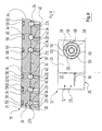
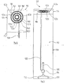
- FIGS. 1, 2, 3, 4 and 9 show a shower device, generally designated by the reference numeral 10, with a panel-like basic body 12 for mounting on a wall, not shown.
- FIGS. 5 to 8 also show mutually perpendicular sections through the shower device 10.
- the main body 12 carries a mixer tap 14, lower right in Figure 1, above a side shower 16 and a shower head 18 at the top, which are connected via a plurality of water pipes 20, 22, some of which are explained below and in the figures 5, 6 , 7 and 8 are each shown in section.
- An upper head shower area 24 of the main body 12 is angled at about 80 ° with respect to a lower vertical main area 26 in the direction of the user side 28 of the main body 12, right in Figure 1, so that the overhead shower area 24 is almost horizontal from the imaginary vertical wall extending in Figure 1 to the left of the Main body 12 is located, extending away into the room.
- the user side 28 is the side of the body 12 from which the shower device 10 is used, in particular actuated, and normally viewed.
- the main body 12 is attached to the main area 26 vertically to the wall. He can stand with his bottom on the ground, but he can also hang with or without contact with the ground on the wall or be fixed to the top of a room ceiling.
- the overhead shower 18 shown in FIGS. 3 and 4 is arranged, which is described in more detail below.
- the main body 12 is composed of a total of a front, user-side panel member 30 and a rear, the user side 28 facing away from panel member 32.
- the panel elements 30, 32 are rectangular plates made of translucent opaque glass, which each have an angled portion for realizing the main area 26 and the overhead shower area 24.
- the mutually facing surfaces (contact surfaces) of the front panel member 30 and the rear panel member 32 are flat and lie flat against each other. At the contact surfaces, the two panel elements 30, 32 are connected to each other, preferably glued.
- a cold water pipe and a hot water pipe both of which are not visible in FIGS. 1 to 9 because of the haze of the glass, result in the form of recesses 34 described below in connection with the other shown water pipes 20 and 22 between the contact surfaces of the underside of the
- the mixer 14 is located in a corresponding receptacle, not shown in detail in the lower region of the vertical main region 26 of the body 12.
- the faucet 14 remote from the ends of the cold water pipe and the hot water pipe are not releasable in a known manner with appropriate connected house water pipes, which lead from the wall, the floor or the ceiling.
- an overhead shower water conduit 22 also shown in Figs. 5 and 6, also delimited by two recesses 34, leads vertically upwardly between the contact surfaces adjacent the side shower water duct 20 to the overhead shower area 24 of the base body 12 and goes there in an illustrated in Figures 7 and 8 in section overhead shower line part 22b.
- the overhead shower pipe part 22b is also realized by corresponding recesses 34 between the contact surfaces. He spans to realize an overhead shower 18 a surface.
- three concentric annular closed water pipe parts 22c with different diameters are interconnected via radial connecting lines, which are not shown in FIGS. 1 to 9 (cf. FIG. 7).
- All water pipes 20, 22 in the base body 12 each have a total circular cross-section; This can be seen in FIGS. 5 to 8. They are each realized in half in the longitudinal direction by two opposite recesses 34, which each have a semicircular cross-section.
- the recesses 34 are formed in the mating surfaces of the front panel member 30 and the rear panel member 32.
- Corresponding semicircular recesses 34 complete in composite panel members 30 and 32 respectively to one of the water pipes 20, 22.
- the water pipes 20, 22 are, as they are limited by the panel members 30, 32 itself, translucent.
- the annular water pipe parts 22 c of the overhead shower pipe part 22 b also have, as in the 3, 4, 7 and 8, in the front panel member 30, a plurality of radially extending water outlet nozzles 40 extending perpendicular to the user-side surface of the front panel member 30.
- the side shower water pipe 20 opens, as shown in Figure 5, in a circular cylindrical receiving opening 36 for the side shower head 38 of the side shower 16.
- the receiving opening 36 is located in the front panel member 30. It extends from the local contact surface with respect to the recess 34 of the side shower -Water line 20, which is located in the rear panel member 26, to the user-side surface of the front panel member 30 and is open on both sides.
- a flat circular cylindrical recess 42 is also arranged around the local recess 34 of the side shower water pipe 20 in the contact surface of the rear panel member 32, whose diameter corresponds approximately to the outer diameter of the receiving opening 36 and which is concentric with the axis of the receiving opening 36.
- the receiving opening 36 further has an internal thread into which a pipe socket 44 of the side shower head 38, which in turn has a corresponding external thread, is screwed.
- the pipe socket 44 extends from a front panel element 30 facing base side of a rotationally symmetrical Mounting body 46 concentric with the axis thereof.
- the mounting body 46 rests with screwed-pipe socket 44 with its basic body 12 facing base side of the user-side surface of the front panel member 30 at.
- a circular flat gasket 48 which is housed in the front panel member 30 and in the base side of the mounting body 46 each in a local sealing groove which is arranged concentrically to the axis of the pipe socket 44 is.
- a plug receptacle 52 for a there fastened, preferably screwed, about rohrfömige connector 54 of the side shower head 38 is connected.
- the plug-in receptacle 52 opens into a hemispherical, outwardly open space into which the water inlet region of the side shower head 38 protrudes.
- the rear panel element 32 in the main region 26 of the main body 12 has two vertically extending receiving grooves 56 for a plurality of white-emitting light-emitting diodes 58.
- the receiving grooves 56 are shown in Figures 2, 5, 6 and 9.
- the LEDs 58 are only shown in Figures 5 and 6.
- the receiving grooves 56 extend along the side shower water pipe 20 and the part of the overhead shower water pipe 22 running in the main area 26.
- the rear panel member 32 also has three circular concentric grooves 60 which are associated with the annular water conduit portions 22c of the overhead shower conduit portion 22b of the overhead shower water conduit 22.
- each receiving groove 60 four light-emitting diodes 58 are arranged at the corners of a respective imaginary square; this is shown in FIG.
- the three imaginary squares are concentric and their sides are parallel.
- the receiving grooves 56 and 60 are recessed in the main area 26 on the rear side facing away from the user side 28 or in the overhead shower area 24 on the upper side of the rear panel element 32. They are on the side facing away from the front panel member 30, so the user side facing away from the body 12, open. From the open side, the LEDs 58 are inserted and fixed in the receiving grooves 56 and 60, as shown in FIGS. 5 to 8.
- the LEDs 58 are connected via known invisible power lines, preferably made of conductive transparent plastic, which are not shown in Figures 1 to 9, with a known, also not shown control and power supply unit.
- the light-emitting diodes 58 As soon as the light-emitting diodes 58 are energized, they emit the corresponding water pipes 10, 22 from the rear side facing away from the user or from the upper side of the main body 12. In this way, the water pipes 10, 22, preferably even the water flows, at least viewed from the user side 28 forth visible. In addition, with the light-emitting diodes 58, the opaque glass is also diffusely illuminated in an area around the water pipes 20, 22.
- the panel members 30, 32 are injected or molded, wherein the recesses 34 for the water pipes 10, 20, for the cold and hot water pipe and the grooves 56 and 60 for the light emitting diodes 58, the receptacle for the mixer tap 14 and the receiving opening 36 for the side shower 16 are molded with. In the latter, the internal thread is introduced. In addition, the power lines for the light emitting diodes are laid, in particular printed. Subsequently, the panel members 30 and 32 are glued with their contact surfaces close together.
- the mixer 14 and the side shower 16 are installed.
- the mounting body 46 is first screwed into the receiving opening 36 with the pipe socket 44 ahead.
- the side shower head 38 with its connector 54 in the Inserted receptacle 52 of the pipe socket 44 preferably screwed.
- the LEDs 58 are inserted into the receiving grooves 56 and 60 and connected via the power lines to the control and power supply unit, which is also attached to the base body 12.
- the prefabricated Düsch worn 10 is then completely attached to the wall, on the floor and / or on the ceiling, the hot water pipe and the cold water pipe are connected to the already existing in or on the wall, the floor or ceiling domestic water pipes.
- the control and supply unit for the LEDs 58 is connected to a power supply line, which is also already laid in or on the wall, floor or ceiling.
- FIGS. 10 to 13 Light-emitting diodes is required.
- the receiving grooves 156 and 160 for the light-emitting diodes and the LEDs in the second embodiment of the user side 128 and the user remote side are visible.
- the contours of the water pipes are more sharply outlined compared to the first embodiment in the second embodiment, and optical effects caused by the water flow are more clearly visible.
- FIG. 13 which shows the shower device 110 from the user side 128, the external fittings of the mixer tap 114 and the side shower 116 are not shown for the sake of clarity.
- the invention is not limited to use in shower facilities. Rather, it can also be used in other types of sanitary facilities, in particular bathtubs, sinks, washbasin or toilet fittings.
- the panel-like basic body 12; 112 can be mounted in a room, instead of on a wall, only on the ceiling or on the floor.
- a water pipe 10, 22; 120, 122 or more or other than the described water pipes 10, 22; 120, 122 may be provided.
- a toilet feed water pipe can be provided.
- the water pipe can be completely or at least partially translucent.
- the recesses 34; 134 for the water pipes 20, 22; 120, 122 may each be half in each case in a different ratio in the two panel elements 30, 32; 130, 132 may be arranged. You can also completely in one of the panel elements 30; 130 or 32; 132 housed.
- the panel-like basic body 12; 112 may be made entirely of glass even in the areas between the water pipes 20, 22; 120, 122 and the user side 28; 128 be made of glass.
- the front panel member 30; 130 be made of a translucent material.
- the main body 12; 112 may be made of a different light-transmitting in particular colored material, preferably of transparent or opaque plastic, in particular acrylic glass, instead of glass.
- the main body 12; 112 may also be formed of a single element.
- the panel elements 30, 32; 130, 132 may be realized instead of in the form of rectangular plates as differently shaped, in particular polygonal, round or oval plates.
- the contact surfaces of the panel elements 30, 32; 130, 132 may instead be curved also complementary, so that they lie flat against each other.
- the panel elements 30, 32; 130, 132 may be bonded together differently instead of each other. For example, they can also be pressed together with screws or clamps.
- the upper region 24; 124 of the panel-like basic body 12; 112 may instead of about 80 ° and by another angle, preferably between 60 ° and 90 ° relative to the main region 26; 126 be angled. But it can also be provided a smaller or larger angle.
- the main body 12; 112 can also be completely flat. For example, it can run vertically and only with Side showers 16; 116 or horizontally on the ceiling and exclusively with overhead showers 18; 118 be equipped.
- the receiving grooves 56, 60; 156, 160 for the LEDs 58 instead of in the rear panel member 32; 132 also in the front panel member 30; 130 or arranged along the contact surfaces.
- receiving grooves 56, 60; 156, 160 may also be provided individual hole-shaped receptacles for the LEDs 58.
- receiving grooves 56, 60; 156, 160 may be housed instead of or in addition to the light-emitting diodes 58 and light guides, which are provided with corresponding bulbs, in particular with isolated in the receiving grooves 65, 60; 156, 160 arranged light-emitting diodes 58, are irradiated.
- LEDs with different emission colors can be controlled variably to the shower device 10; 110, in particular the water pipes 20, 22; 120, 122, to be irradiated in different colors.
- a water parameter in particular the water temperature and / or the flow rate, characterizing color are radiated.
- warm water can be assigned the color red and cold water the color blue.
- the corresponding water pipe 20, 22; 120, 122 green and red when water is stopped.
- a color change can also be made only for purely aesthetic reasons.
- the second embodiment can be completely dispensed with the bulbs.
Landscapes
- Health & Medical Sciences (AREA)
- Life Sciences & Earth Sciences (AREA)
- Engineering & Computer Science (AREA)
- Hydrology & Water Resources (AREA)
- Public Health (AREA)
- Water Supply & Treatment (AREA)
- Bathtubs, Showers, And Their Attachments (AREA)
Applications Claiming Priority (1)
| Application Number | Priority Date | Filing Date | Title |
|---|---|---|---|
| DE102006055756A DE102006055756B4 (de) | 2006-11-25 | 2006-11-25 | Sanitäreinrichtung mit einem tafelartigen Grundkörper |
Publications (1)
| Publication Number | Publication Date |
|---|---|
| EP1930510A2 true EP1930510A2 (fr) | 2008-06-11 |
Family
ID=39144544
Family Applications (1)
| Application Number | Title | Priority Date | Filing Date |
|---|---|---|---|
| EP07022163A Withdrawn EP1930510A2 (fr) | 2006-11-25 | 2007-11-15 | Dispositif sanitaire doté d'un corps de base de type planche |
Country Status (4)
| Country | Link |
|---|---|
| US (1) | US20080120772A1 (fr) |
| EP (1) | EP1930510A2 (fr) |
| CN (1) | CN101187217A (fr) |
| DE (1) | DE102006055756B4 (fr) |
Cited By (2)
| Publication number | Priority date | Publication date | Assignee | Title |
|---|---|---|---|---|
| WO2009024219A1 (fr) * | 2007-08-21 | 2009-02-26 | Hansgrohe Ag | Robinet sanitaire avec unité d'écoulement en verre |
| EP2990547A1 (fr) * | 2014-09-01 | 2016-03-02 | Michael Gerloff | Salle de bains dotee d'un bloc sanitaire destine a la douche ou au bain et element de paroi avant |
Families Citing this family (4)
| Publication number | Priority date | Publication date | Assignee | Title |
|---|---|---|---|---|
| US11602032B2 (en) | 2019-12-20 | 2023-03-07 | Kohler Co. | Systems and methods for lighted showering |
| USD1031925S1 (en) * | 2022-08-24 | 2024-06-18 | Hansgrohe Se | Shower |
| USD1031926S1 (en) * | 2022-08-24 | 2024-06-18 | Hansgrohe Se | Shower |
| USD1064188S1 (en) * | 2022-08-24 | 2025-02-25 | Hansgrohe Se | Shower |
Family Cites Families (24)
| Publication number | Priority date | Publication date | Assignee | Title |
|---|---|---|---|---|
| US3571816A (en) * | 1969-08-29 | 1971-03-23 | Lee W Mccullough | Composite bathroom fixture |
| US4055301A (en) * | 1976-07-19 | 1977-10-25 | Rain Jet Corporation | Shower head with divergent impact effect nozzle |
| US4457031A (en) * | 1982-04-28 | 1984-07-03 | The Swan Corporation | Modular pre-plumbed shower unit |
| US4801091A (en) * | 1988-03-31 | 1989-01-31 | Sandvik Arne P | Pulsating hot and cold shower head |
| CA2038054A1 (fr) * | 1990-03-12 | 1991-09-13 | Kazuo Hiraishi | Appareil de douche |
| US5070549A (en) * | 1990-07-18 | 1991-12-10 | Millburn Associates Limited | Shower cabinet |
| US5078862A (en) * | 1991-04-11 | 1992-01-07 | Justice Ralph R | Washer standpipe drain visual filter |
| US5365620A (en) * | 1993-07-26 | 1994-11-22 | Macleod Robert P | Outdoor shower apparatus |
| US5933883A (en) * | 1997-02-04 | 1999-08-10 | Biancamano; Vincent | Pool structure and fountain apparatus |
| DE19903377C1 (de) * | 1999-01-28 | 2000-04-27 | Manfred Buesselmann | Ganzkörper-Nebelbadvorrichtung und Verfahren zum Verabreichen eines Ganzkörper-Nebelbades |
| NO311284B1 (no) * | 1999-09-20 | 2001-11-12 | Fjordbad As | Boble- eller massasjebadekar, samt ventilinnretning for et slikt badekar |
| US6357058B1 (en) * | 1999-09-28 | 2002-03-19 | Vincent Biancamano | Pool structure and fountain apparatus |
| US6317903B1 (en) * | 2000-04-06 | 2001-11-20 | Bains Ultra Inc. | Bathtub design with therapeutical treatment devices |
| US6349428B1 (en) * | 2000-04-20 | 2002-02-26 | Moen Incorporated | Pullout hand-held shower |
| US6460202B1 (en) * | 2000-11-07 | 2002-10-08 | Sherwood-Templeton Coal Company, Inc. | Transparent fitting for spas and the like |
| US6694541B2 (en) * | 2000-11-07 | 2004-02-24 | Sherwood-Templeton Coal Company, Inc. | Transparent fitting for spas and the like |
| DE10148900A1 (de) * | 2001-09-21 | 2003-04-10 | Hansgrohe Ag | Installationseinheit für sanitäre Einrichtung |
| DE10260206A1 (de) * | 2002-12-13 | 2004-06-24 | Hansgrohe Ag | Brausehalter |
| US6973682B2 (en) * | 2003-04-19 | 2005-12-13 | Eli Zhadanov | Device for showering and the like |
| NZ525880A (en) * | 2003-05-14 | 2005-11-25 | Methven Ltd | Method and apparatus for producing droplet spray |
| DE102005018285A1 (de) * | 2005-04-13 | 2006-10-19 | Hansgrohe Ag | System mit einer sanitären Armatur und einem Wasserauslass an einer Wand und einer plattenartigen Abdeckung |
| US20070118983A1 (en) * | 2005-11-29 | 2007-05-31 | Tatum Bradford T | Portable spa |
| DE202006006507U1 (de) * | 2006-04-20 | 2006-08-31 | Schulte Duschkabinenbau Gmbh & Co. Kg | Anordnung für eine Scheibenbefestigung und/oder Raumabtrennung, insbesondere eine Duschabtrennung oder Dampfkabine |
| ITMN20080006A1 (it) * | 2008-03-07 | 2009-09-08 | A Q A S R L | Doccia per bagno |
-
2006
- 2006-11-25 DE DE102006055756A patent/DE102006055756B4/de not_active Expired - Fee Related
-
2007
- 2007-11-15 EP EP07022163A patent/EP1930510A2/fr not_active Withdrawn
- 2007-11-26 US US11/945,036 patent/US20080120772A1/en not_active Abandoned
- 2007-11-26 CN CNA2007101693695A patent/CN101187217A/zh active Pending
Cited By (2)
| Publication number | Priority date | Publication date | Assignee | Title |
|---|---|---|---|---|
| WO2009024219A1 (fr) * | 2007-08-21 | 2009-02-26 | Hansgrohe Ag | Robinet sanitaire avec unité d'écoulement en verre |
| EP2990547A1 (fr) * | 2014-09-01 | 2016-03-02 | Michael Gerloff | Salle de bains dotee d'un bloc sanitaire destine a la douche ou au bain et element de paroi avant |
Also Published As
| Publication number | Publication date |
|---|---|
| DE102006055756B4 (de) | 2011-06-16 |
| DE102006055756A1 (de) | 2008-06-19 |
| US20080120772A1 (en) | 2008-05-29 |
| CN101187217A (zh) | 2008-05-28 |
Similar Documents
| Publication | Publication Date | Title |
|---|---|---|
| DE3327829C2 (fr) | ||
| DE3901162C2 (de) | Duschkabine | |
| EP1930510A2 (fr) | Dispositif sanitaire doté d'un corps de base de type planche | |
| DE60320586T2 (de) | Zuführsystem für ein fluid mit integrierter lichtquelle | |
| EP1435817B1 (fr) | Cuvette de lavage pourvue d'un dispositif d'eclairage | |
| DE102013107339A1 (de) | Bausatz zum Verkleiden und Verrohren von Sanitärräumen | |
| EP2761114B1 (fr) | Bassin doté de margelles éclairées | |
| EP1422352A2 (fr) | Bassin, en particulier lavabo en verre | |
| DE19641337B4 (de) | Sanitärhalterung | |
| DE20105323U1 (de) | Möbel | |
| DE102011101913A1 (de) | Schallabsorbierende Leuchte | |
| DE4239801A1 (en) | Wash basin or sink unit with integral tap housing - has housing formed in a recess in sinks surround or sink work area | |
| DE202011051310U1 (de) | Duschrinne mit Dauerbeleuchtung | |
| EP1435480B1 (fr) | Robinetterie sanitaire | |
| DE102004051661B3 (de) | Leuchte und Lichtquelleneinheit zur Ausleuchtung einer Gebäudefläche oder einer Gebäudeteilfläche | |
| EP2172595B1 (fr) | Robinetterie d'eau | |
| DE102007049532A1 (de) | In ein Trägerelement einsetzbare Leuchte | |
| DE2941418A1 (de) | Ventilarmatur | |
| DE102006052403A1 (de) | Armatur für Badewannen | |
| DE102004011634B3 (de) | Plattenheizkörper | |
| EP1112415B1 (fr) | Dispositif dote d'elements sanitaires et/ou de cuisine | |
| EP1446534A1 (fr) | Bloc de robinetterie sanitaire | |
| EP1223253B1 (fr) | Ensemble sanitaire | |
| WO2006108605A1 (fr) | Systeme dote d'une robinetterie sanitaire et d'une sortie d'eau sur un mur et d'un element de recouvrement en forme de plaque | |
| DE19649937A1 (de) | Badewannenarmatur mit integrierter Schmutzwasserrücklaufsicherung |
Legal Events
| Date | Code | Title | Description |
|---|---|---|---|
| PUAI | Public reference made under article 153(3) epc to a published international application that has entered the european phase |
Free format text: ORIGINAL CODE: 0009012 |
|
| AK | Designated contracting states |
Kind code of ref document: A2 Designated state(s): AT BE BG CH CY CZ DE DK EE ES FI FR GB GR HU IE IS IT LI LT LU LV MC MT NL PL PT RO SE SI SK TR |
|
| AX | Request for extension of the european patent |
Extension state: AL BA HR MK RS |
|
| STAA | Information on the status of an ep patent application or granted ep patent |
Free format text: STATUS: THE APPLICATION IS DEEMED TO BE WITHDRAWN |
|
| 18D | Application deemed to be withdrawn |
Effective date: 20120601 |