EP1930526A2 - Embout moulé pour profilé - Google Patents
Embout moulé pour profilé Download PDFInfo
- Publication number
- EP1930526A2 EP1930526A2 EP07450226A EP07450226A EP1930526A2 EP 1930526 A2 EP1930526 A2 EP 1930526A2 EP 07450226 A EP07450226 A EP 07450226A EP 07450226 A EP07450226 A EP 07450226A EP 1930526 A2 EP1930526 A2 EP 1930526A2
- Authority
- EP
- European Patent Office
- Prior art keywords
- wall
- fitting
- strip
- longitudinal groove
- profile strip
- Prior art date
- Legal status (The legal status is an assumption and is not a legal conclusion. Google has not performed a legal analysis and makes no representation as to the accuracy of the status listed.)
- Withdrawn
Links
Images


Classifications
-
- E—FIXED CONSTRUCTIONS
- E04—BUILDING
- E04F—FINISHING WORK ON BUILDINGS, e.g. STAIRS, FLOORS
- E04F19/00—Other details of constructional parts for finishing work on buildings
- E04F19/02—Borders; Finishing strips, e.g. beadings; Light coves
- E04F19/04—Borders; Finishing strips, e.g. beadings; Light coves for use between floor or ceiling and wall, e.g. skirtings
- E04F19/0495—Plinths fixed around wall openings or around corners of walls
-
- A—HUMAN NECESSITIES
- A47—FURNITURE; DOMESTIC ARTICLES OR APPLIANCES; COFFEE MILLS; SPICE MILLS; SUCTION CLEANERS IN GENERAL
- A47B—TABLES; DESKS; OFFICE FURNITURE; CABINETS; DRAWERS; GENERAL DETAILS OF FURNITURE
- A47B95/00—Fittings for furniture
- A47B95/04—Keyplates; Ornaments or the like
- A47B95/043—Protecting rims, buffers or the like
-
- E—FIXED CONSTRUCTIONS
- E04—BUILDING
- E04F—FINISHING WORK ON BUILDINGS, e.g. STAIRS, FLOORS
- E04F19/00—Other details of constructional parts for finishing work on buildings
- E04F19/02—Borders; Finishing strips, e.g. beadings; Light coves
- E04F19/04—Borders; Finishing strips, e.g. beadings; Light coves for use between floor or ceiling and wall, e.g. skirtings
- E04F2019/0404—Borders; Finishing strips, e.g. beadings; Light coves for use between floor or ceiling and wall, e.g. skirtings characterised by the material
- E04F2019/0431—Borders; Finishing strips, e.g. beadings; Light coves for use between floor or ceiling and wall, e.g. skirtings characterised by the material of two or more materials
Definitions
- the invention relates to an attachable to a profile strip fitting, which is a plug-in receptacle for a front end portion of grooved, attachable to a wall strip body with an end portion on the side facing away from the wall outside form-fitting encompassing edge web and two the wall-side back of the end portion outside of the L jossnutung forms behind attacks.
- the invention is therefore based on the object, an attachable to a profile strip fitting of the type described in such a way that a backlash-free mounting on the one hand and an increased peel resistance of the molding of the profile strip on the other hand can be guaranteed.
- the required for the attachment of the profile strip on the wall Leksnutung comprising at least one longitudinal groove, determines the height of the fitting relative to the profile strip, so that the engaging in such a longitudinal groove on the back of the profile strip clamping jaw prevents displacement of the molding transverse to the profile strip.
- the spring effect of the clamping jaw can be ensured in different ways, particularly simple construction conditions arise when the clamping jaw consists of separated by a running in the direction of the longitudinal slot gap, against each other resilient neck parts. These attachment parts are based upon engagement in the respective longitudinal groove of the profile strip on the mutually opposite groove walls under a resilient bias, which ensures increased frictional forces between the clamping attachment and the groove walls. Since generally two longitudinal grooves are provided in the profile strips, which are used as pedestal or cornice strips, a particularly good attachment of the fittings to the front end portions of the profile strips can be achieved in that the socket of the fitting two each in a longitudinal groove of the strip body frontally forms engaging clamping approaches.
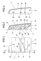
- the clamping lugs 12 thus have a spring action transverse to the longitudinal grooves 10, so that the clamping lugs 13 create a resilient bias under clamping to the groove walls, whereby a secure hold of the fitting 1 on the front end portion 2 of the profile strip 3 is achieved.
- the fitting 1 after the 4 and 5 represents a the outer end portions 2 of two profile strips 3 connecting outer corner between two walls 7 in.
- the end cap after the Fig. 1 and 2 consistent manner the strip body of the moldings 3 are overlapped on the side facing away from the wall 7 outside by edge webs 5, which protrude from a bottom 14.
- the edge webs 5 are in turn from the bottom 14 upstanding stops 6 with respect to form a Aufsteckability for the front end portion 2 of the moldings 3.
- the fitting 1 may also be formed as an inner corner.
- the plug-in receptacle for the profile strips 3 is again achieved between an edge web 5 and stops 6, which rise from a bottom 14, wherein an additional resilient support of the inner corner forming fitting 1 at the front end portion 2 of the profile strips 3 is achieved by split clamping lugs 12.
- the mold piece 1 is provided in the miter area between the profiled strips 3 and therefore forms a bottom 14 between the miter surfaces of the profile strips 3. From this bottom 14, the edge webs 5 project according to the miter angle, in turn to a socket for the end-side end portions 2 of the moldings 3 form.
- the holder of the molding 1 is carried out in the manner already described in connection with the other embodiments, on the one hand with the help of free spaces 8 of the profile strips 3 engaging stops 6 and on the other hand of resilient clamping lugs 12, which in turn consist of two resilient attachment parts 13 and in the longitudinal grooves 10th the longitudinal groove 9 of the profile strips 3 engage.
- the fitting 1 is provided for an inner corner, is from the 8 and 9 probably immediately recognizable that fittings 1 in the miter area in an analogous manner are also suitable for outside corners.
Landscapes
- Engineering & Computer Science (AREA)
- Architecture (AREA)
- Civil Engineering (AREA)
- Structural Engineering (AREA)
- Clamps And Clips (AREA)
- Closures For Containers (AREA)
Applications Claiming Priority (1)
| Application Number | Priority Date | Filing Date | Title |
|---|---|---|---|
| AT0085406U AT9912U1 (de) | 2006-12-07 | 2006-12-07 | Auf eine profilleiste aufsteckbares formstück |
Publications (2)
| Publication Number | Publication Date |
|---|---|
| EP1930526A2 true EP1930526A2 (fr) | 2008-06-11 |
| EP1930526A3 EP1930526A3 (fr) | 2010-03-17 |
Family
ID=39154351
Family Applications (1)
| Application Number | Title | Priority Date | Filing Date |
|---|---|---|---|
| EP07450226A Withdrawn EP1930526A3 (fr) | 2006-12-07 | 2007-12-06 | Embout moulé pour profilé |
Country Status (2)
| Country | Link |
|---|---|
| EP (1) | EP1930526A3 (fr) |
| AT (1) | AT9912U1 (fr) |
Cited By (2)
| Publication number | Priority date | Publication date | Assignee | Title |
|---|---|---|---|---|
| JP2010112165A (ja) * | 2008-11-05 | 2010-05-20 | Frank Sondermann | 被覆材の縁をカバーするためのベースボード及びベースボードのための接続部材 |
| JP2014070360A (ja) * | 2012-09-28 | 2014-04-21 | Panasonic Corp | 幅木セット |
Family Cites Families (2)
| Publication number | Priority date | Publication date | Assignee | Title |
|---|---|---|---|---|
| DE29809577U1 (de) * | 1998-05-28 | 1998-10-01 | Hülsta-Werke Hüls GmbH & Co KG, 48703 Stadtlohn | Schmale Endkappe für Dekorleisten |
| DE10149408C1 (de) * | 2001-10-06 | 2003-01-09 | Xaver Gruenwald Gmbh | Vorrichtung zur Befestigung von Leistenschienen, insbesondere von als Sockelleisten ausgebildeten Leistenschienen |
-
2006
- 2006-12-07 AT AT0085406U patent/AT9912U1/de not_active IP Right Cessation
-
2007
- 2007-12-06 EP EP07450226A patent/EP1930526A3/fr not_active Withdrawn
Cited By (4)
| Publication number | Priority date | Publication date | Assignee | Title |
|---|---|---|---|---|
| JP2010112165A (ja) * | 2008-11-05 | 2010-05-20 | Frank Sondermann | 被覆材の縁をカバーするためのベースボード及びベースボードのための接続部材 |
| EP2184423A3 (fr) * | 2008-11-05 | 2010-12-08 | Frank Sondermann | Plinthe pour le recouvrement d'un bord de revêtement |
| US8122658B2 (en) | 2008-11-05 | 2012-02-28 | Kueberit Profile Systems GmbH & Co. KG | Reversible baseboard for covering a flooring border |
| JP2014070360A (ja) * | 2012-09-28 | 2014-04-21 | Panasonic Corp | 幅木セット |
Also Published As
| Publication number | Publication date |
|---|---|
| EP1930526A3 (fr) | 2010-03-17 |
| AT9912U1 (de) | 2008-05-15 |
Similar Documents
| Publication | Publication Date | Title |
|---|---|---|
| DE69405363T2 (de) | Verbinder mit elastischem Verriegelungselement | |
| DE2623709A1 (de) | Bauelementensatz | |
| DE102012102339A1 (de) | Verbindung für elastische oder plattenförmige Bauelemente, Profilschieber und Fußbodenbelag | |
| DE102007020271A1 (de) | Verbindung für Fußbodenelemente | |
| DE202007001781U1 (de) | Schubkasten | |
| DE3733329C1 (de) | Kabelfuehrungskanal zur Aufnahme von Starkstrom-,Schwachstrom- und Fernmeldekabel | |
| DE102015108275A1 (de) | Eckblende für Hohlprofil-Eckverbinder, Eckverbinder, Eckverbinder-Bausatz, Rahmenstruktur und Schutzgitter | |
| WO2010102735A1 (fr) | Panneau | |
| EP2991170B1 (fr) | Agencement doté d'éléments modulaires et de moyens de codage réglables | |
| EP0308958A2 (fr) | Chaîne porteuse pour lignes de transport d'énérgie | |
| DE9207859U1 (de) | Glasscheibenhalter | |
| EP3100641B1 (fr) | Panneau arrière de tiroir, tiroir et meuble a tiroir | |
| EP1948459B1 (fr) | Unite de vitre sur laquelle est montee une languette decorative | |
| EP1930526A2 (fr) | Embout moulé pour profilé | |
| DE2710592C3 (de) | Klammer zur Befestigung eines Zierleistenrahmens auf einer Windschutzscheibe insbesondere im Kraftfahrzeugbau | |
| DE102010060672B4 (de) | Fenster- oder Türrahmen | |
| DE10322633B3 (de) | Schienenanordnung zum Abdecken oder Überbrücken von Fugen, insbesondere für Fußböden | |
| DE2446912C3 (de) | Elektrische Baueinheit zum Montieren in einer elektrischen Anlage | |
| EP1646756B1 (fr) | Systeme d'assemblage pour rails profiles | |
| EP2620579B1 (fr) | Elément de liaison destiné à la liaison de pièces profilées | |
| DE3200282A1 (de) | Klammer zur halterung von leisten, insbesondere zierleisten und verfahren zur befestigung der zierleisten auf platten | |
| DE4224888C1 (en) | Vehicle number-plate mounting - has deeper insertion groove between chamfered corners with insertion slits and hinging plate-supports locking in groove | |
| EP2090789B1 (fr) | Connecteur pour tiges de profil en forme de cannelure et agencement de connexion | |
| DE2608271B2 (de) | Seitenführungsschiene für eine Lamellenjalousie | |
| DE639459C (de) | Unverlierbares Druckstueck an Schrauben, insbesondere zum Festklemmen von elektrischen Leitungsdraehten |
Legal Events
| Date | Code | Title | Description |
|---|---|---|---|
| PUAI | Public reference made under article 153(3) epc to a published international application that has entered the european phase |
Free format text: ORIGINAL CODE: 0009012 |
|
| AK | Designated contracting states |
Kind code of ref document: A2 Designated state(s): AT BE BG CH CY CZ DE DK EE ES FI FR GB GR HU IE IS IT LI LT LU LV MC MT NL PL PT RO SE SI SK TR |
|
| AX | Request for extension of the european patent |
Extension state: AL BA HR MK RS |
|
| PUAL | Search report despatched |
Free format text: ORIGINAL CODE: 0009013 |
|
| AK | Designated contracting states |
Kind code of ref document: A3 Designated state(s): AT BE BG CH CY CZ DE DK EE ES FI FR GB GR HU IE IS IT LI LT LU LV MC MT NL PL PT RO SE SI SK TR |
|
| AX | Request for extension of the european patent |
Extension state: AL BA HR MK RS |
|
| AKY | No designation fees paid | ||
| STAA | Information on the status of an ep patent application or granted ep patent |
Free format text: STATUS: THE APPLICATION IS DEEMED TO BE WITHDRAWN |
|
| REG | Reference to a national code |
Ref country code: DE Ref legal event code: 8566 |
|
| 18D | Application deemed to be withdrawn |
Effective date: 20100701 |