EP1930582A2 - Kraftstoffeinspritzvorrichtung für Motoren und Betriebsverfahren für die Vorrichtung - Google Patents
Kraftstoffeinspritzvorrichtung für Motoren und Betriebsverfahren für die Vorrichtung Download PDFInfo
- Publication number
- EP1930582A2 EP1930582A2 EP07111359A EP07111359A EP1930582A2 EP 1930582 A2 EP1930582 A2 EP 1930582A2 EP 07111359 A EP07111359 A EP 07111359A EP 07111359 A EP07111359 A EP 07111359A EP 1930582 A2 EP1930582 A2 EP 1930582A2
- Authority
- EP
- European Patent Office
- Prior art keywords
- fuel
- plunger
- high pressure
- common rail
- electromagnetic valve
- Prior art date
- Legal status (The legal status is an assumption and is not a legal conclusion. Google has not performed a legal analysis and makes no representation as to the accuracy of the status listed.)
- Granted
Links
Images


Classifications
-
- F—MECHANICAL ENGINEERING; LIGHTING; HEATING; WEAPONS; BLASTING
- F02—COMBUSTION ENGINES; HOT-GAS OR COMBUSTION-PRODUCT ENGINE PLANTS
- F02M—SUPPLYING COMBUSTION ENGINES IN GENERAL WITH COMBUSTIBLE MIXTURES OR CONSTITUENTS THEREOF
- F02M63/00—Other fuel-injection apparatus having pertinent characteristics not provided for in groups F02M39/00 - F02M57/00 or F02M67/00; Details, component parts, or accessories of fuel-injection apparatus, not provided for in, or of interest apart from, the apparatus of groups F02M39/00 - F02M61/00 or F02M67/00; Combination of fuel pump with other devices, e.g. lubricating oil pump
- F02M63/02—Fuel-injection apparatus having several injectors fed by a common pumping element, or having several pumping elements feeding a common injector; Fuel-injection apparatus having provisions for cutting-out pumps, pumping elements, or injectors; Fuel-injection apparatus having provisions for variably interconnecting pumping elements and injectors alternatively
- F02M63/0225—Fuel-injection apparatus having a common rail feeding several injectors ; Means for varying pressure in common rails; Pumps feeding common rails
-
- F—MECHANICAL ENGINEERING; LIGHTING; HEATING; WEAPONS; BLASTING
- F02—COMBUSTION ENGINES; HOT-GAS OR COMBUSTION-PRODUCT ENGINE PLANTS
- F02M—SUPPLYING COMBUSTION ENGINES IN GENERAL WITH COMBUSTIBLE MIXTURES OR CONSTITUENTS THEREOF
- F02M59/00—Pumps specially adapted for fuel-injection and not provided for in groups F02M39/00 -F02M57/00, e.g. rotary cylinder-block type of pumps
- F02M59/20—Varying fuel delivery in quantity or timing
- F02M59/24—Varying fuel delivery in quantity or timing with constant-length-stroke pistons having variable effective portion of stroke
- F02M59/243—Varying fuel delivery in quantity or timing with constant-length-stroke pistons having variable effective portion of stroke caused by movement of cylinders relative to their pistons
-
- F—MECHANICAL ENGINEERING; LIGHTING; HEATING; WEAPONS; BLASTING
- F02—COMBUSTION ENGINES; HOT-GAS OR COMBUSTION-PRODUCT ENGINE PLANTS
- F02M—SUPPLYING COMBUSTION ENGINES IN GENERAL WITH COMBUSTIBLE MIXTURES OR CONSTITUENTS THEREOF
- F02M59/00—Pumps specially adapted for fuel-injection and not provided for in groups F02M39/00 -F02M57/00, e.g. rotary cylinder-block type of pumps
- F02M59/20—Varying fuel delivery in quantity or timing
- F02M59/36—Varying fuel delivery in quantity or timing by variably-timed valves controlling fuel passages to pumping elements or overflow passages
- F02M59/366—Valves being actuated electrically
Definitions
- the present invention relates to a fuel injection apparatus and applies to a diesel engine, etc. equipped with an accumulator fuel injection apparatus, the apparatus being composed such that; high pressure fuel pumps are provided each of which compresses fuel introduced into its plunger room to high pressure by its plunger fitted in its plunger barrel and reciprocated by means of a fuel cam to supply the compressed fuel to a common rail, and high pressure fuel accumulated in the common rail is injected periodically at determined injection timing into each of the cylinders of the engine, and a method of operating the engine equipped with the apparatus.
- An accumulator fuel injection equipment used in a diesel engine is provided with high pressure fuel injection pumps each of which compresses fuel introduced into its plunger room to high pressure by its plunger fitted in its plunger barrel and reciprocated by means of a fuel cam, and high pressure fuel accumulated in the common rail is supplied to each of fuel injection valves to be injected periodically at determined injection timing into each engine cylinder.
- discharge duration of high pressure fuel from each of the high pressure pumps is controlled by controlling opening/closing of a low pressure side fuel feed passage by means of an electromagnetic valve provided to each pump as disclosed for example in Japanese Laid-Open Patent Application No. 64-73166 (patent literature 1) and Japanese Laid-Open Patent Application No. 62-258160 (patent literature 2).
- FIG.2B represents a diagram showing a fuel cam lift and opening/closing of the electromagnetic valve vs. crankshaft rotation angles in the electronically-controlled accumulator fuel injection apparatus disclosed in the patent literature 1.
- the electromagnetic valve is closed on the way the cam lift is increasing to begin fuel discharge from the high pressure fuel pump, and opened when the cam lift is at its maximum to allow high pressure fuel remaining in the plunger room (volume of the plunger room is at minimum, i.e. dead volume) of the high pressure pump to spill out to the fuel feed line (low pressure side fuel line) .
- FIG.5 is a drawing for explaining working of a high pressure fuel pump 020 in the conventional accumulator fuel injection apparatus.
- change of lift of fuel cam 04, open or close of inlet/spill port 010a, and direction of fuel flow at inlet/spill port 010a are shown as the fuel cam 04 is rotated.
- the electromagnetic valve is closed on the way the cam lift is increasing to begin fuel discharge from the high pressure fuel pump, and opened when the cam lift is at its maximum to allow high pressure fuel remaining in the plunger room to spill to the fuel feed line.
- the present invention was made in light of problems mentioned above, and the object of the present invention is to provide a fuel injection apparatus for engines, with which occurrence of cavitation erosion on constituent parts of the high pressure fuel pump and fuel feed line in the apparatus is suppressed and high durability is attained even in the case of a high pressure fuel pump increased largely in capacity.
- the present invention proposes a fuel injection apparatus for engines, the apparatus comprising a plurality of high pressure fuel pumps in each of which fuel supplied to a plunger room is compressed by a plunger driven by a fuel cam to reciprocate in a plunger barrel, the compressed fuel being discharged to a common rail by at timing controlled by an electromagnetic valve, and high pressure fuel accumulated in the common rail being injected into engine cylinders by injection valves at controlled timing, wherein a controller is provided which controls such that fuel is discharged from the plunger room by closing the electromagnetic valve in an up stroke of the plunger, the electromagnetic valve is kept closed for some period in an down stroke of the plunger, then the electromagnetic valve is opened to allow the plunger room to be communicated with a fuel feed/spill passage.
- the invention proposes a method of operating a fuel injection apparatus for engines, the apparatus comprising a plurality of high pressure fuel pumps, in each of which fuel supplied to a plunger room is compressed by a plunger driven by a fuel cam to reciprocate in a plunger barrel, the compressed fuel is discharged to a common rail at timing controlled by an electromagnetic valve, and high pressure fuel accumulated in the common rail is injected into engine cylinders by injection valves at controlled timing, wherein each of said high pressure fuel pumps is controlled such that fuel is discharged from the plunger room by closing the electromagnetic valve in an up stroke of the plunger, the electromagnetic valve is kept closed for some period in a down stroke of the plunger, then the electromagnetic valve is opened to allow the plunger room to be communicated with a fuel feed/spill passage.
- fuel is discharged from the plunger room in an up stroke of the plunger until the plunger reaches its top dead center by closing the inlet passage by the electromagnetic valve, the electromagnetic valve is kept closed in a down stroke of the plunger during a certain period of crankshaft rotation, then the electromagnetic valve is opened to allow the plunger room to be communicated with the fuel feed/spill passage, so the plunger room is communicated with the fuel feed/spill passage when fuel pressure in the plunger room has lowered to a pressure level in the fuel feed/spill passage or lower.
- the plunger moves down from its top dead center while keeping the fuel feed/spill passage closed by the electromagnetic valve, the plunger moves down receiving pressure in the plunger room, so a part of energy used to drive the high pressure pump can be recovered.
- the fuel feed pump for supplying fuel to the plunger room can be small sized, and energy required to drive the fuel feed pump can be reduced as compared with the apparatus of prior art.
- a common rail pressure sensor is provided for detecting pressure in the common rail, and said controller is composed to retard opening time of said electromagnetic valve in the down stroke of the plunger as pressure in the common rail increases, based on the detected pressure.
- opening time of the fuel feed/spill passage is retarded when pressure in the common rail is high so that the electromagnetic valve allows the fuel feed/spill passage to be opened when pressure in the plunger room becomes a pressure equal to or lower than that in the fuel feed/spill passage. Therefore, pressure in the plunger room does not exceed pressure in the fuel feed/spill passage when the electromagnetic valve is opened, and spilling out of high pressure fuel in the plunger room to the fuel feed/spill passage can be evaded.
- it is suitable to detect directly discharge pressure of the high pressure fuel pumps to control timing of opening of the electromagnetic valves.
- the present invention proposes a fuel injection apparatus for engines, the apparatus comprising a plurality of high pressure fuel pumps, in each of which fuel supplied to a plunger room is compressed by a plunger driven by a fuel cam to reciprocate in a plunger barrel, the compressed fuel is discharged to a common rail at timing controlled by an electromagnetic valve, and high pressure fuel accumulated in the common rail is injected into engine cylinders by injection valves at controlled timing, wherein said plunger has a lead edge by which an inlet/spill port of the plunger barrel is closed in an up stroke of the plunger to allow fuel in the plunger room to be discharged until the plunger reaches its top dead center and is opened in a down stroke of the plunger to allow the plunger room to be communicated with a fuel feed/spill passage.
- rack-pinion mechanism for rotating the plungers by sliding the rack
- rack drive device for sliding the rack
- common rail pressure sensor for detecting pressure in the common rail and inputting the detected pressure to said rack drive device
- controller to allow the rack drive device to slide the rack to rotate the plungers based on the detected pressure so that timing of opening of the inlet/spill port by each of the plungers in down-stroke thereof is retarded as pressure in the common rail increases.
- the plunger of the high pressure fuel pump is formed to have a lead edge, by which the inlet/spill port of the plunger barrel is closed in the up stroke of the plunger driven by the fuel cam to reciprocate in the plunger barrel to discharge fuel from the plunger room to the common rail and the inlet/spill port is opened in the down stroke of the plunger to allow the plunger room to be communicated with the fuel feed/spill passage, and timing of opening and closing of the inlet/spill port by the lead edge of the plunger can be varied by rotating the plunger by means of the rack-pinion mechanism.
- the plunger moves down from its top dead center while the inlet/spill port remains closed, so the plunger moves down receiving pressure in the plunger room, so a part of energy used to drive the high pressure pump can be recovered.
- the fuel feed pump for supplying fuel to the plunger room can be small sized, and energy required to drive the fuel feed pump can be reduced as compared with the apparatus of prior art.
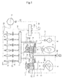
- FIG.1 is schematic representation of over-all configuration of a first embodiment of the electronically-controlled accumulation fuel injection apparatus for a diesel engine according to the invention.
- a plurality of high pressure pumps 20 (two pumps in this example) are provided.
- Each of the high pressure pumps 20 has a plunger barrel 20a and a plunger 2 fitted in the plunger barrel 20a for reciprocation.
- Each of the plungers 2 is driven to reciprocate in each of the plunger barrels 20a by a fuel cam 4 formed on a camshaft 5 to correspond to each of the pumps 20, and compresses fuel supplied to each of plunger rooms 3.
- a discharge pipe 12 of each of the high pressure pumps 20 connects each of the plunger rooms 3 to a common rail 7.
- a check valve 11 is provided at the outlet of each plunger room 3 to the discharge pipe 12 so that fuel can flow only in direction from the plunger rooms 3 to the common rail 7.
- Fuel is supplied to the plunger rooms 3 by means of a fuel feed pump 18 via a fuel feed pipe 201 and each of fuel inlet passages 20b provided to each of the plunger barrels 20a.
- Each of the fuel inlet passages 20b is opened or closed by a poppet valve 1a of each of electromagnetic valves 1.
- the controller 100 receives a rotation angles of the crankshaft 6 detected by a crank angle sensor 15, engine loads detected by an engine load detector 16, and common rail pressure (fuel pressure in the common rail 7) detected by a common rail pressure detector 14.
- the controller 100 outputs a control signal to control timing of opening and closing of the electromagnetic valve 1 of each of the high pressure pumps 20 based on the detected values.
- the controller 100 has also a function of adjusting fuel injection timing and quantity of the injection valves 9 by controlling the fuel control valves 21 based on the detected values.
- fuel supplied by the fuel feed pump 18 through the fuel feed pipe 201 is allowed to enter the plunger room 3 through the fuel inlet passage 20b during a period when the inlet passage 20b is opened by the poppet valve 1a of the electromagnetic valve 1 which is actuated by a command signal from the controller 100.
- High pressure fuel accumulated in the common rail 7 is injected from the fuel injection valve 9 into each engine cylinder 10 at controlled injection timing.
- the present invention relates to controlling of high pressure fuel pumps 20 of a fuel injection apparatus composed as mentioned above.
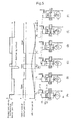
- FIG.2A is a diagram showing fuel cam lift, opening/closing of the electromagnetic valve, and state of fuel spilling from the plunger room through the inlet/spill port of the plunger barrel vs. crankshaft rotation angles in the case of the first embodiment of the invention
- FIG. 2B is a drawing as in FIG.2A in the case of an apparatus of prior art.
- the controller 100 controls timing of opening and closing of the electromagnetic valve 1, as shown in FIG.2A , such that; the inlet passage 20b is closed at crank angle ⁇ 1 while the plunger 2 is moving up driven by the fuel cam 4 in order to supply fuel to the common rail 7 through the discharge pipe 12, the inlet passage 20b is retained closed until at crank angle ⁇ 3 in a down stroke of the plunger 2, the crank angle ⁇ 3 being a crankshaft rotation angle when the crankshaft rotated by ⁇ from ⁇ 2 at which the plunger 2 is at the top dead center of the cam lift, then the inlet passage 20b is opened at crank angle ⁇ 3 in order to communicate the plunger room 3 to the fuel feed pipe 201 through the inlet passage 20b.
- fuel is discharged from the plunger room 3 in an up stroke of the plunger 2 until the plunger 2 reaches its top dead center at crank angle ⁇ 2 by closing the inlet passage 20b, the inlet passage 20b is kept closed in a down stroke of the plunger 2 during crankshaft rotation of a crank angle of ⁇ until at crank angle ⁇ 3 , at which the inlet passage 20b is opened and the plunger room 3 is communicated to the fuel feed pipe 201 via the poppet valve 1a of the electromagnetic valve 1, so the plunger room 3 is communicated to the fuel feed pipe 201 when fuel pressure in the plunger room 3 has lowered to a pressure level equal to or lower than that in the fuel feed pipe 201.
- the plunger 2 moves down from its top dead center while keeping the electromagnetic valve 1 closed, the plunger 2 moves down receiving pressure in the plunger room, so a part of energy used to drive the high pressure pump can be recovered.
- the fuel feed pump 18 for supplying fuel to the plunger room 3 can be small sized, and energy required to drive the fuel feed pump 18 can be reduced as compared with the apparatus of prior art.
- a common rail pressure sensor 14 is provided to detect pressure in the common rail 7 and input it in the controller 100, and the controller 100 controls the electromagnetic valve 1 so that the higher the pressure in the common rail 7, the later the inlet passage 20b opens.
- opening time of the inlet passage 20b is retarded when pressure in the common rail 7 is high so that the electromagnetic valve 1 allows the inlet passage 20b to open when pressure in the plunger room 3 becomes a pressure equal to or lower than that in the fuel feed pipe 201. Therefore, pressure in the plunger room 3 does not exceed pressure in the fuel feed pipe 201 when the inlet passage 20b is opened, and spilling out of high pressure fuel in the plunger room 3 through the inlet passage 20b to the fuel feed pipe 201 can be evaded.
- FIG. 3 is schematic representation of an over-all configuration of a second embodiment of the electronically-controlled accumulation fuel injection apparatus for a diesel engine according to the invention.
- a plunger having a leading edge that enables the high pressure pump to function similar to that of the first embodiment is provided instead of the electromagnetic valve in the first embodiment.
- a plurality of high pressure pumps 20 are provided.
- Each of the high pressure pumps 20 has a plunger barrel 20a in which a plunger 2 having a leading edge 2a is fitted for reciprocation.
- Each of the plungers 2 is driven to reciprocate in each of the plunger barrels 20a by a fuel cam 4 formed on a camshaft 5 to correspond to each of the pumps 20, and compresses fuel supplied to each of plunger rooms 3.
- a discharge pipe 12 of each of the high pressure pumps 20 connects each of the plunger rooms 3 to a common rail 7.
- a check valve 11 is provided at the outlet of the plunger room to the discharge pipe so that fuel can flow only from the plunger room 3 to the common rail 7.
- Fuel is supplied to the plunger rooms 3 by means of a fuel feed pump 18 via a fuel feed pipe 201.
- a fuel inlet/spill port 10a communicating to the fuel feed pipe 201 is opened and closed by the leading edge 2a of the plunger 2 formed at the top part thereof as the plunger reciprocates in the plunger barrel 20a.
- the fuel is injected from the injection valve 9 into the engine cylinder.
- Fuel injection timing and quantity of each injection valve 9 are controlled by each of fuel control valves 21 which are controlled by a controller 100.
- the plungers 2 can be rotated by combination of pinions 52 and a rack 51.
- FIG. 3 is represented only to show that each of the plungers 2 can be rotated by sliding the rack 51, actual mechanism of rotating the plungers 2 is similar to that of a so-called in-line fuel injection pump widely known. Timing of opening and closing of the inlet/spill port 10a by the lead edge 2a of the plunger 2 can be varied by rotating the plunger 2.
- An end of the rack 51 is connected to a rack drive device 50 of position controlling solenoid type.
- the rack drive device 50 controls rotation of the plunger 2 by controlling the slide position of the rack 51.
- the controller 100 receives rotation angles of the crankshaft 6 detected by a crank angle sensor 15, engine loads detected by an engine load detector 16, and common rail pressure(fuel pressure in the common rail 7) detected by a common rail pressure detector 14.
- the controller 100 allows the rack drive device 50 to slide the rack 51 based on the detected values so that rotation position of the plungers 2 is controlled based on the detected values.
- the controller 100 has also a function of adjusting fuel injection timing and quantity of the injection valves 9 by controlling the fuel control valves 21 based on the detected values.
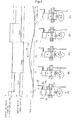
- FIG.4 is a drawing for explaining working of the high pressure fuel pump 20 in the accumulation fuel injection apparatus of the second embodiment.
- a lift curve of the fuel cam 4 open or close of the inlet/spill port 10a, and direction of fuel flow at the inlet/spill port 10a vs. crankshaft rotation angle are shown.
- the port 10a remains closed during the crankshaft rotates further by a crank angle of ⁇ until the plunger 2 moves down to a position at which the port 10a begins to be opened by the lead edge 2a of the plunger 2, as shown in (D).
- the plunger 2 of the high pressure fuel pump 20 is formed to have the lead edge 2a, by which the inlet/spill port 10a is closed in the up stroke of the plunger 2 driven by the fuel cam 4 to reciprocate in the plunger barrel 20a to discharge fuel from the plunger room 3 to the common rail 7, and the port 10a is opened in the down stroke of the plunger 2 to allow the plunger room 3 to be communicated with the fuel feed line, timing of opening and closing of the port 10a by the lead edge 2a of the plunger 2 can be varied by rotating the plunger 2 by means of the rack-pinion mechanism.
- the plunger room 3 is communicated with the feed pipe 201 in a state of pressure in the plunger room 3, which is same as or lower than that in the fuel feed/spill passage (inlet/spill port 10a and fuel feed pipe 201), pressure pulsation in the fuel feed/spill passage due to back-flow of high pressure fuel does not occur, and problems such as fuel leak and so on due to pressure pulsation do not occur.
- the plunger 2 moves down from its top dead center while the inlet/spill port 10a remains closed, the plunger 2 moves down receiving pressure in the plunger room 20, so a part of energy used to drive the high pressure pump can be recovered.
- the fuel feed pump 18 for supplying fuel to the plunger room 3 can be small sized, and energy required to drive the fuel feed pump 18 can be reduced as compared with the apparatus of prior art.
- the electromagnetic valve is closed until the plunger of the high pressure fuel pump reaches the top dead center in its up stroke to discharge fuel, and the electromagnetic valve is kept closed in the down stroke of the plunger until when pressure in the plunger room reduces, then the electromagnetic valve is opened to allow the plunger room to be communicated with the fuel feed/spill passage; or the plunger is formed to have a leading edge, by which the inlet/spill port of the plunger barrel is closed at a crank angle in the up stroke of the plunger to discharge fuel and opened in the down stroke thereof at a crank angle to allow the plunger room to be communicated with a fuel feed/spill passage, so the plunger room is communicated with the fuel feed/spill passage when pressure in the plunger room has decreased to a level equal to or lower than that in the fuel feed/spill passage, resulting in that the occurrence of rapid backflow of high pressure fuel remaining in the plunger room to the fuel feed/spill passage at high speed, which occurs in an apparatus of prior art, can be evaded
Landscapes
- Engineering & Computer Science (AREA)
- Chemical & Material Sciences (AREA)
- Combustion & Propulsion (AREA)
- Mechanical Engineering (AREA)
- General Engineering & Computer Science (AREA)
- Fuel-Injection Apparatus (AREA)
Applications Claiming Priority (1)
| Application Number | Priority Date | Filing Date | Title |
|---|---|---|---|
| JP2006324641A JP4616822B2 (ja) | 2006-11-30 | 2006-11-30 | エンジンの燃料噴射装置及び運転方法 |
Publications (3)
| Publication Number | Publication Date |
|---|---|
| EP1930582A2 true EP1930582A2 (de) | 2008-06-11 |
| EP1930582A3 EP1930582A3 (de) | 2011-09-07 |
| EP1930582B1 EP1930582B1 (de) | 2019-03-06 |
Family
ID=39322583
Family Applications (1)
| Application Number | Title | Priority Date | Filing Date |
|---|---|---|---|
| EP07111359.1A Ceased EP1930582B1 (de) | 2006-11-30 | 2007-06-29 | Kraftstoffeinspritzvorrichtung für Motoren und Betriebsverfahren für die Vorrichtung |
Country Status (3)
| Country | Link |
|---|---|
| US (1) | US7546831B2 (de) |
| EP (1) | EP1930582B1 (de) |
| JP (1) | JP4616822B2 (de) |
Cited By (2)
| Publication number | Priority date | Publication date | Assignee | Title |
|---|---|---|---|---|
| CN101644219B (zh) * | 2009-02-27 | 2011-08-10 | 中国重汽集团重庆燃油喷射系统有限公司 | 重型车用柴油机电控高压共轨系统 |
| CN101713359B (zh) * | 2008-10-01 | 2014-03-05 | 曼柴油机欧洲股份公司 | 具有带可以磁的方式促动的抽吸阀的高压泵的燃料喷射系统 |
Families Citing this family (9)
| Publication number | Priority date | Publication date | Assignee | Title |
|---|---|---|---|---|
| DE102007006865A1 (de) * | 2007-02-12 | 2008-08-14 | Siemens Ag | Verfahren zum Steuern einer Brennkraftmaschine und Brennkraftmaschine |
| US9989026B2 (en) * | 2012-02-17 | 2018-06-05 | Ford Global Technologies, Llc | Fuel pump with quiet rotating suction valve |
| US20140338637A1 (en) * | 2013-05-15 | 2014-11-20 | Caterpillar Inc. | Common rail system having mechanical unit pumps |
| DE102013009147B4 (de) * | 2013-05-31 | 2015-11-05 | Mtu Friedrichshafen Gmbh | Verfahren zum Regeln eines Drucks und Anordnung zum Regeln eines Drucks |
| GB2524110A (en) * | 2014-03-14 | 2015-09-16 | Gm Global Tech Operations Inc | A fluid pump assembly for an internal combustion engine |
| DE102014225982A1 (de) * | 2014-12-16 | 2016-06-16 | Robert Bosch Gmbh | Pumpe, insbesondere Kraftstoffhochdruckpumpe |
| US11668261B2 (en) | 2019-04-22 | 2023-06-06 | Cummins Inc. | Pump active inlet valve spilling residual pressure |
| US11486386B2 (en) | 2019-11-06 | 2022-11-01 | Cummins Inc. | Active control valve for a fluid pump |
| WO2021245984A1 (ja) * | 2020-06-03 | 2021-12-09 | 日立Astemo株式会社 | 電磁弁制御装置 |
Family Cites Families (18)
| Publication number | Priority date | Publication date | Assignee | Title |
|---|---|---|---|---|
| US4643155A (en) * | 1984-10-05 | 1987-02-17 | Olin Corporation | Variable stroke, electronically controlled fuel injection control system |
| JPH07122422B2 (ja) | 1986-05-02 | 1995-12-25 | 日本電装株式会社 | 燃料噴射装置 |
| GB8703419D0 (en) * | 1987-02-13 | 1987-03-18 | Lucas Ind Plc | Fuel injection pump |
| DE3885689T2 (de) * | 1987-09-16 | 1994-03-24 | Nippon Denso Co | Hochdruckverstellpumpe. |
| JP2754541B2 (ja) * | 1987-10-12 | 1998-05-20 | 株式会社デンソー | 可変吐出量高圧ポンプ |
| JP2690734B2 (ja) | 1987-09-16 | 1997-12-17 | 株式会社デンソー | 可変吐出量高圧ポンプ |
| DE4441113C1 (de) * | 1994-11-18 | 1996-04-04 | Bosch Gmbh Robert | Kraftstoffhochdruckpumpe für Brennkraftmaschinen |
| JP3666085B2 (ja) * | 1995-12-06 | 2005-06-29 | いすゞ自動車株式会社 | 燃料噴射ポンプ |
| DE69720603T2 (de) * | 1996-07-05 | 2004-03-04 | Nippon Soken, Inc., Nishio | Hochdruckpumpe |
| EP0964150B1 (de) * | 1998-04-15 | 2005-06-15 | Denso Corporation | Brennstoffeinspritzsystem für eine Brennkraftmaschine |
| JP3562351B2 (ja) * | 1998-11-24 | 2004-09-08 | トヨタ自動車株式会社 | 内燃機関の燃料ポンプ制御装置 |
| JP2001041128A (ja) * | 1999-07-28 | 2001-02-13 | Toyota Motor Corp | 高圧燃料ポンプ |
| EP1130250A1 (de) * | 2000-03-01 | 2001-09-05 | Wärtsilä NSD Schweiz AG | Saugdrosselpumpe |
| JP2002115623A (ja) * | 2000-10-05 | 2002-04-19 | Mitsubishi Electric Corp | 可変吐出量燃料供給装置 |
| DE10162988B4 (de) * | 2001-12-20 | 2004-01-15 | Siemens Ag | Vorrichtung und Verfahren zur Regelung des Steuerventils einer Hochdruckpumpe |
| DE602004002105T2 (de) * | 2004-06-30 | 2007-02-08 | C.R.F. S.C.P.A. | Hochdruckpumpe mit variabler Förderrate für ein Brennstoffeinspritzsystem |
| EP1674716B1 (de) * | 2004-12-23 | 2010-12-15 | C.R.F. Società Consortile per Azioni | Kraftstoffeinspritzeinrichtung mit Hochdruckkraftstoffpumpe mit verändlicher Durchflussmenge |
| EP1674718B1 (de) * | 2004-12-23 | 2007-03-14 | C.R.F. Società Consortile per Azioni | Speichereinspritzsystem für eine Brennkraftmaschine |
-
2006
- 2006-11-30 JP JP2006324641A patent/JP4616822B2/ja not_active Expired - Fee Related
-
2007
- 2007-06-29 EP EP07111359.1A patent/EP1930582B1/de not_active Ceased
- 2007-06-29 US US11/822,019 patent/US7546831B2/en active Active
Cited By (2)
| Publication number | Priority date | Publication date | Assignee | Title |
|---|---|---|---|---|
| CN101713359B (zh) * | 2008-10-01 | 2014-03-05 | 曼柴油机欧洲股份公司 | 具有带可以磁的方式促动的抽吸阀的高压泵的燃料喷射系统 |
| CN101644219B (zh) * | 2009-02-27 | 2011-08-10 | 中国重汽集团重庆燃油喷射系统有限公司 | 重型车用柴油机电控高压共轨系统 |
Also Published As
| Publication number | Publication date |
|---|---|
| EP1930582A3 (de) | 2011-09-07 |
| JP2008138567A (ja) | 2008-06-19 |
| EP1930582B1 (de) | 2019-03-06 |
| US20080127943A1 (en) | 2008-06-05 |
| JP4616822B2 (ja) | 2011-01-19 |
| US7546831B2 (en) | 2009-06-16 |
Similar Documents
| Publication | Publication Date | Title |
|---|---|---|
| EP1930582B1 (de) | Kraftstoffeinspritzvorrichtung für Motoren und Betriebsverfahren für die Vorrichtung | |
| EP1927744B1 (de) | Kraftstoffeinspritzvorrichtung für einen Motor und Betriebsverfahren für einen mit der Vorrichtung ausgestatteten Motor | |
| US8136508B2 (en) | Selective displacement control of multi-plunger fuel pump | |
| CN1057146C (zh) | 用于燃料喷射系统的高压泵 | |
| JP3574681B2 (ja) | 内燃機関の燃料噴射装置 | |
| US20030029423A1 (en) | Method, computer program, control and/or regulating unit, and fuel system for an internal combustion engine, in particular with direct injection | |
| EP1612402A1 (de) | Hochdruckpumpe mit variabler Förderrate für ein Brennstoffeinspritzsystem | |
| US8025488B2 (en) | Transfer pump for high-pressure gasoline injection | |
| EP1918573B1 (de) | Kraftstoffeinspritzvorrichtung für Motoren | |
| US5040511A (en) | Fuel injection device for internal combustion engines, in particular unit fuel injector | |
| KR940011345B1 (ko) | 디젤엔진용 연료분사장치 | |
| US5458103A (en) | Fuel injection arrangement for internal combustion engines | |
| US6626149B2 (en) | Injection system | |
| KR940011343B1 (ko) | 선분사 장치를 갖는 디젤엔진용 연료분사장치 | |
| US5377636A (en) | Solenoid operated pump-line-nozzle fuel injection system and inline pump therefor | |
| US4537352A (en) | Fuel injection apparatus | |
| CN102654091B (zh) | 特别是燃料泵的液压泵 | |
| KR890000756B1 (ko) | 내연기관의 유닛인젝터 | |
| DE4211068A1 (de) | Luftpresser | |
| GB2252135A (en) | Fuel injection pump for supplying fuel and a further liquid to diesel engines | |
| JPS5937265A (ja) | 内燃機関の燃料噴射装置 | |
| JPH04284156A (ja) | 分配型燃料噴射ポンプ | |
| JP2006090256A (ja) | エンジンの燃料供給装置 | |
| JP2002227739A (ja) | 燃料噴射ポンプ | |
| JPS60216065A (ja) | 内燃機関のユニツトインジエクタ |
Legal Events
| Date | Code | Title | Description |
|---|---|---|---|
| PUAI | Public reference made under article 153(3) epc to a published international application that has entered the european phase |
Free format text: ORIGINAL CODE: 0009012 |
|
| AK | Designated contracting states |
Kind code of ref document: A2 Designated state(s): AT BE BG CH CY CZ DE DK EE ES FI FR GB GR HU IE IS IT LI LT LU LV MC MT NL PL PT RO SE SI SK TR |
|
| AX | Request for extension of the european patent |
Extension state: AL BA HR MK RS |
|
| PUAL | Search report despatched |
Free format text: ORIGINAL CODE: 0009013 |
|
| AK | Designated contracting states |
Kind code of ref document: A3 Designated state(s): AT BE BG CH CY CZ DE DK EE ES FI FR GB GR HU IE IS IT LI LT LU LV MC MT NL PL PT RO SE SI SK TR |
|
| AX | Request for extension of the european patent |
Extension state: AL BA HR MK RS |
|
| RIC1 | Information provided on ipc code assigned before grant |
Ipc: F02M 59/36 20060101ALI20110803BHEP Ipc: F02M 63/02 20060101ALI20110803BHEP Ipc: F02M 59/20 20060101AFI20110803BHEP |
|
| 17P | Request for examination filed |
Effective date: 20120307 |
|
| AKX | Designation fees paid |
Designated state(s): AT DE FR GB |
|
| 17Q | First examination report despatched |
Effective date: 20130129 |
|
| STAA | Information on the status of an ep patent application or granted ep patent |
Free format text: STATUS: EXAMINATION IS IN PROGRESS |
|
| RAP1 | Party data changed (applicant data changed or rights of an application transferred) |
Owner name: MITSUBISHI HEAVY INDUSTRIES ENGINE & TURBOCHARGER, |
|
| GRAP | Despatch of communication of intention to grant a patent |
Free format text: ORIGINAL CODE: EPIDOSNIGR1 |
|
| STAA | Information on the status of an ep patent application or granted ep patent |
Free format text: STATUS: GRANT OF PATENT IS INTENDED |
|
| INTG | Intention to grant announced |
Effective date: 20180921 |
|
| GRAS | Grant fee paid |
Free format text: ORIGINAL CODE: EPIDOSNIGR3 |
|
| GRAA | (expected) grant |
Free format text: ORIGINAL CODE: 0009210 |
|
| STAA | Information on the status of an ep patent application or granted ep patent |
Free format text: STATUS: THE PATENT HAS BEEN GRANTED |
|
| AK | Designated contracting states |
Kind code of ref document: B1 Designated state(s): AT DE FR GB |
|
| REG | Reference to a national code |
Ref country code: GB Ref legal event code: FG4D |
|
| REG | Reference to a national code |
Ref country code: AT Ref legal event code: REF Ref document number: 1104879 Country of ref document: AT Kind code of ref document: T Effective date: 20190315 |
|
| REG | Reference to a national code |
Ref country code: DE Ref legal event code: R096 Ref document number: 602007057760 Country of ref document: DE |
|
| REG | Reference to a national code |
Ref country code: AT Ref legal event code: MK05 Ref document number: 1104879 Country of ref document: AT Kind code of ref document: T Effective date: 20190306 |
|
| REG | Reference to a national code |
Ref country code: DE Ref legal event code: R097 Ref document number: 602007057760 Country of ref document: DE |
|
| PG25 | Lapsed in a contracting state [announced via postgrant information from national office to epo] |
Ref country code: AT Free format text: LAPSE BECAUSE OF FAILURE TO SUBMIT A TRANSLATION OF THE DESCRIPTION OR TO PAY THE FEE WITHIN THE PRESCRIBED TIME-LIMIT Effective date: 20190306 |
|
| PLBE | No opposition filed within time limit |
Free format text: ORIGINAL CODE: 0009261 |
|
| STAA | Information on the status of an ep patent application or granted ep patent |
Free format text: STATUS: NO OPPOSITION FILED WITHIN TIME LIMIT |
|
| 26N | No opposition filed |
Effective date: 20191209 |
|
| GBPC | Gb: european patent ceased through non-payment of renewal fee |
Effective date: 20190629 |
|
| PG25 | Lapsed in a contracting state [announced via postgrant information from national office to epo] |
Ref country code: GB Free format text: LAPSE BECAUSE OF NON-PAYMENT OF DUE FEES Effective date: 20190629 |
|
| PG25 | Lapsed in a contracting state [announced via postgrant information from national office to epo] |
Ref country code: FR Free format text: LAPSE BECAUSE OF NON-PAYMENT OF DUE FEES Effective date: 20190630 |
|
| PGFP | Annual fee paid to national office [announced via postgrant information from national office to epo] |
Ref country code: DE Payment date: 20210602 Year of fee payment: 15 |
|
| REG | Reference to a national code |
Ref country code: DE Ref legal event code: R119 Ref document number: 602007057760 Country of ref document: DE |
|
| PG25 | Lapsed in a contracting state [announced via postgrant information from national office to epo] |
Ref country code: DE Free format text: LAPSE BECAUSE OF NON-PAYMENT OF DUE FEES Effective date: 20230103 |