EP1930630A1 - Roue à transmission de puissance avec amortisseurs de vibration - Google Patents
Roue à transmission de puissance avec amortisseurs de vibration Download PDFInfo
- Publication number
- EP1930630A1 EP1930630A1 EP07122566A EP07122566A EP1930630A1 EP 1930630 A1 EP1930630 A1 EP 1930630A1 EP 07122566 A EP07122566 A EP 07122566A EP 07122566 A EP07122566 A EP 07122566A EP 1930630 A1 EP1930630 A1 EP 1930630A1
- Authority
- EP
- European Patent Office
- Prior art keywords
- rim
- hub
- power transmission
- annular portion
- transmission wheel
- Prior art date
- Legal status (The legal status is an assumption and is not a legal conclusion. Google has not performed a legal analysis and makes no representation as to the accuracy of the status listed.)
- Withdrawn
Links
- 230000005540 biological transmission Effects 0.000 title claims abstract description 108
- 238000002485 combustion reaction Methods 0.000 claims description 20
- 230000000717 retained effect Effects 0.000 claims description 5
- 238000005096 rolling process Methods 0.000 claims description 3
- 238000013016 damping Methods 0.000 description 10
- 238000006073 displacement reaction Methods 0.000 description 7
- 238000004891 communication Methods 0.000 description 3
- 239000012530 fluid Substances 0.000 description 3
- 230000001133 acceleration Effects 0.000 description 2
- 230000006835 compression Effects 0.000 description 2
- 238000007906 compression Methods 0.000 description 2
- 239000000446 fuel Substances 0.000 description 2
- 239000004519 grease Substances 0.000 description 2
- 239000000463 material Substances 0.000 description 2
- 238000007789 sealing Methods 0.000 description 2
- 238000001816 cooling Methods 0.000 description 1
- 230000003247 decreasing effect Effects 0.000 description 1
- 238000010586 diagram Methods 0.000 description 1
- 238000002347 injection Methods 0.000 description 1
- 239000007924 injection Substances 0.000 description 1
- 238000005461 lubrication Methods 0.000 description 1
- 238000012986 modification Methods 0.000 description 1
- 230000004048 modification Effects 0.000 description 1
- 239000007858 starting material Substances 0.000 description 1
- 238000011144 upstream manufacturing Methods 0.000 description 1
Images








Classifications
-
- F—MECHANICAL ENGINEERING; LIGHTING; HEATING; WEAPONS; BLASTING
- F16—ENGINEERING ELEMENTS AND UNITS; GENERAL MEASURES FOR PRODUCING AND MAINTAINING EFFECTIVE FUNCTIONING OF MACHINES OR INSTALLATIONS; THERMAL INSULATION IN GENERAL
- F16H—GEARING
- F16H55/00—Elements with teeth or friction surfaces for conveying motion; Worms, pulleys or sheaves for gearing mechanisms
- F16H55/02—Toothed members; Worms
- F16H55/14—Construction providing resilience or vibration-damping
-
- F—MECHANICAL ENGINEERING; LIGHTING; HEATING; WEAPONS; BLASTING
- F16—ENGINEERING ELEMENTS AND UNITS; GENERAL MEASURES FOR PRODUCING AND MAINTAINING EFFECTIVE FUNCTIONING OF MACHINES OR INSTALLATIONS; THERMAL INSULATION IN GENERAL
- F16D—COUPLINGS FOR TRANSMITTING ROTATION; CLUTCHES; BRAKES
- F16D3/00—Yielding couplings, i.e. with means permitting movement between the connected parts during the drive
- F16D3/50—Yielding couplings, i.e. with means permitting movement between the connected parts during the drive with the coupling parts connected by one or more intermediate members
- F16D3/64—Yielding couplings, i.e. with means permitting movement between the connected parts during the drive with the coupling parts connected by one or more intermediate members comprising elastic elements arranged between substantially-radial walls of both coupling parts
- F16D3/68—Yielding couplings, i.e. with means permitting movement between the connected parts during the drive with the coupling parts connected by one or more intermediate members comprising elastic elements arranged between substantially-radial walls of both coupling parts the elements being made of rubber or similar material
-
- F—MECHANICAL ENGINEERING; LIGHTING; HEATING; WEAPONS; BLASTING
- F16—ENGINEERING ELEMENTS AND UNITS; GENERAL MEASURES FOR PRODUCING AND MAINTAINING EFFECTIVE FUNCTIONING OF MACHINES OR INSTALLATIONS; THERMAL INSULATION IN GENERAL
- F16H—GEARING
- F16H55/00—Elements with teeth or friction surfaces for conveying motion; Worms, pulleys or sheaves for gearing mechanisms
- F16H55/32—Friction members
- F16H55/36—Pulleys
-
- F—MECHANICAL ENGINEERING; LIGHTING; HEATING; WEAPONS; BLASTING
- F16—ENGINEERING ELEMENTS AND UNITS; GENERAL MEASURES FOR PRODUCING AND MAINTAINING EFFECTIVE FUNCTIONING OF MACHINES OR INSTALLATIONS; THERMAL INSULATION IN GENERAL
- F16H—GEARING
- F16H55/00—Elements with teeth or friction surfaces for conveying motion; Worms, pulleys or sheaves for gearing mechanisms
- F16H55/32—Friction members
- F16H55/36—Pulleys
- F16H2055/366—Pulleys with means providing resilience or vibration damping
Definitions
- the present invention relates to power transmission wheels with torsional dampers.
- ATV all-terrain vehicles
- snowmobiles transmit the power from their engine to their wheel(s) via a flexible power transmitting element. This is achieved using a first power transmission wheel on the output shaft of the engine and second power transmission wheel in operative connection with the wheel(s) onto which the flexible power transmitting element is engaged.
- the flexible power transmitting element used is a notched belt
- the power transmission wheels are in the form of notched belt pulleys.
- the flexible power transmitting element used is a chain
- the power transmission wheels are in the form of sprockets.
- the torque produced by an internal combustion engine is variable, having torque peaks at the combustion events and torque lows in between combustion events.
- the vehicle be lightweight and that the engine also be lightweight and responsive. However, this can only be achieved up to a certain degree.
- the use of heavy components in the drive train of the vehicle can result in tangible load variations.
- reducing the weight of the crank drive can result in increased vibrations.
- the invention provides a power transmission wheel having a hub and a rim.
- the hub has a central annular portion.
- the central annular portion has an inner surface and an outer surface.
- the inner surface is configured for operatively engaging a power transmitting shaft.
- the rim has an inner annular portion and an outer annular portion.
- the central annular portion of the hub is disposed inside the inner annular portion of the rim.
- the outer annular portion of the rim has an outer surface configured for operatively engaging a flexible power transmitting element.
- At least one hub blade extends axially from the hub towards the rim and is disposed radially between the inner and outer annular portions of the rim.
- At least one rim blade extends axially from the rim towards the hub and extends radially from one of the inner and outer annular portions of the rim towards the other of the inner and outer annular portions.
- the power transmission wheel has at least two elastomeric dampers. Each damper is interposed between one of the at least one hub blade and one of the at least one rim blade.
- a rolling-element bearing is disposed between the outer surface of the central annular portion of the hub and an inner surface of the inner annular portion of the rim.
- the at least one hub blade is four hub blades
- the at least one rim blade is four rim blades
- the at least two elastomeric dampers are eight elastomeric dampers.
- the four hub blades are equally spaced around a circumference of the hub.
- the four rim blades are equally spaced around a circumference of the rim.
- Eight arcs are defined between the four hub blades and the four rim blades along the outer surface of the outer annular portion of the rim.
- Four of the eight arcs have a first arc length.
- Four of the eight arcs have a second arc length.
- the first arc length is greater than the second arc length.
- the hub and the rim are disposed such that the arcs having the first arc length and the arcs having the second arc length alternate along a circumference of the outer surface of the outer annular portion.
- Four of the eight elastomeric dampers have a first width.
- Each of the elastomeric dampers have a second width. The first width being greater than the second width.
- Each of the four elastomeric dampers having the first width is interposed between one of the hub blades and one of the rim blades which define therebetween one of the four arcs having the first arc length.
- Each of the four elastomeric dampers having the second width is interposed between one of the hub blades and one of the rim blades which define therebetween one of the four arcs having the second arc length.
- the elastomeric dampers having the first width have a greater volume than the elastomeric dampers having the second width.
- the rolling-element bearing is a needle bearing.
- the rolling element bearing is at least partially axially aligned with the outer surface of the outer annular portion of the rim.
- the outer surface of the rim is configured for operatively engaging a flexible power transmitting element by being toothed for operatively engaging one of a notched belt and a chain.
- the at least one rim blade extends from the inner annular portion of the rim to the outer annular portion of the rim.
- a bolt is provided for fastening the power transmission wheel to an end of an output shaft of an internal combustion engine, and a ring is disposed between the bolt and the rim.
- the output shaft has a shoulder.
- the power transmission wheel is disposed between the shoulder and the ring such that the power transmission wheel is retained on the output shaft.
- an amount of friction between the ring and the rim can be adjusted by tightening or loosening the bolt.
- the relative movement of the rim with respect to the hub can be adjusted by the amount of friction.
- the at least two elastomeric dampers each have at least one protrusion disposed on each side thereof. An amount of friction between the protrusions and the hub and the rim determines an amount of pre-tensioning in the at least two elastomeric dampers.
- the invention provides a vehicle comprising a frame, at least one front wheel mounted to the frame, at least one rear wheel mounted to the frame, and an engine mounted to the frame.
- the engine has a crankshaft, a transmission operatively connected to the engine, and an output shaft having a portion extending from the transmission.
- the output shaft is operatively connected to the crankshaft via the transmission.
- a first power transmission wheel is disposed on the portion of the output shaft which extends from the transmission.
- the first power transmission wheel has a hub and a rim.
- the hub has a central annular portion.
- the central annular portion has an inner surface and an outer surface.
- the inner surface is configured for operatively engaging the output shaft.
- the rim has an inner annular portion and an outer annular portion.
- the central annular portion of the hub is disposed inside the inner annular portion of the rim.
- At least one hub blade extends axially from the hub towards the rim and is disposed radially between the inner and outer annular portions of the rim.
- At least one rim blade extends axially from the rim towards the hub and extends radially from one of the inner and outer annular portions of the rim towards the other of the inner and outer annular portions.
- the first power transmission wheel has at least two elastomeric dampers. Each damper is interposed between one of the at least one hub blade and one of the at least one rim blade.
- a rolling-element bearing is disposed between the outer surface of the central annular portion of the hub and an inner surface of the inner annular portion of the rim.
- a second power transmission wheel is operatively connected to the rear wheel.
- a flexible power transmitting element engages the first power transmission wheel and the second power transmission wheel.
- Embodiments of the present invention each have at least one of the above-mentioned objects and/or aspects, but do not necessarily have all of them. It should be understood that some aspects of the present invention that have resulted from attempting to attain the above-mentioned objects may not satisfy these objects and/or may satisfy other objects not specifically recited therein.
- Fig. 1 is a side view of an internal combustion engine having a power transmission wheel according to the present invention
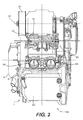
- Fig. 2 is a top plan view of the internal combustion engine shown in Fig. 1 , with an oil pump device of the engine shown in partial cross-section;
- Fig. 3 is a top view of internal components of the internal combustion engine shown in Figs. 1 and 2 ;
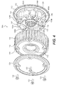
- Fig. 4 is an exploded view of a first embodiment of a power transmission wheel according to the present invention.
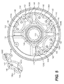
- Fig. 5 is an end view of the hub and elastomeric dampers of the power transmission wheel of Fig. 4 ;
- Fig. 6 is a perspective view of the rim and elastomeric dampers, some of which have been removed, of the power transmission wheel of Fig. 4 ;
- Fig. 7 is a side view of the power transmission wheel of Fig. 4 ;
- Fig. 8 is a cross-section of the power transmission wheel of Fig. 4 taken through line A-A of Fig. 7 ;
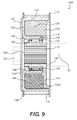
- Fig. 9 is a cross-section of the power transmission wheel of Fig. 4 taken through line B-B of Fig. 8 ;
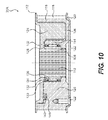
- Fig. 10 is a cross-section of the power transmission wheel of Fig. 4 taken through line C-C of Fig. 8 ;
- Fig. 11 is a side view of a second embodiment of a power transmission wheel according to the present invention.
- Fig. 12 is a cross-section of the power transmission wheel of Fig. 11 taken through line D-D of Fig. 11 ;
- Fig. 13 is a cross-section of the power transmission wheel of Fig. 11 taken through line E-E of Fig. 12 ;
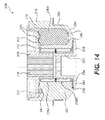
- Fig. 14 is a cross-section of the power transmission wheel of Fig. 11 taken through line F-F of Fig. 12 ;
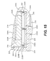
- Fig. 15 is a close-up view of area G of Fig. 13 ;
- Fig. 16 is a schematic diagram illustrating variations in the rotational speed of the crankshaft
- Fig. 17 is a side view of a motorcycle powered by the engine of Fig. 1 ;
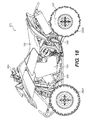
- Fig. 18 is a side view of an all-terrain vehicle (ATV) powered by the engine of Fig. 1 .
- ATV all-terrain vehicle
- an internal combustion engine 100 has a power unit case 1.
- the power unit case 1 includes a crankcase 2 that is divided into a cylinder block portion 3, which includes the upper part of the crankcase 2 and a cylinder block 5, and a lower crankcase half 6 along a separating plane 4.
- An oil sump 7 is secured to the lower crankcase half 6.
- a cylinder head assembly 62 sits atop the cylinder block 5.
- the cylinder block 5 has two cylinders (not shown) inside each of which one of the pistons 27 or 28 reciprocates. It is contemplated that the engine could also have one, three, or four cylinders.
- each of the pistons 27, 28 together with the side wall of its corresponding cylinder and the corresponding portion of the cylinder head assembly 62 forms a combustion chamber (not shown).
- the displacement of the engine 100 is preferably 750 cc (cubic centimeters).
- the displacement of the engine 100 is preferably at least 700 cc. It is also contemplated that the displacement of the engine 100 could be at least 800 cc or at least 1000 cc. It is also contemplated that the displacement of the engine 100 could be less than 1600 cc or less than 1200 cc
- the internal combustion engine 100 of the present invention is preferably a four-cycle engine, at least one intake valve per cylinder (not shown) and at least one exhaust valve per cylinder (not shown) are provided in the cylinder head assembly 62. Two intake valves and two exhaust valves per cylinder are preferably provided.
- a fuel injector (not shown) and a spark plug (not shown) per cylinder are also provided in the cylinder head assembly 62.
- a pair of throttle bodies 64 are used to regulate the quantity of air entering the combustion chambers.
- An air intake manifold (not shown) or an airbox (not shown) or both, are provided upstream of and in fluid communication with the throttle bodies 64.
- An exhaust manifold (not shown) in fluid communication with each combustion chamber is provided on the side of the cylinder block 5 opposite the side where the throttle bodies 64 are provided.
- the exhaust manifold is in fluid communication with the exhaust system of the vehicle incorporating the engine 100. It would be understood that the engine 100 also has other elements and systems not specifically shown and/or described in the present application. These can include, but are not limited to, a starter motor, an oil filter, a cooling system, an electrical system, and a fuel injection system.
- the power unit case 1 also includes an integrated transmission housing 42 which can be made integrally with the crankcase 2 or fastened to the crankcase 2, with bolts for example.
- the power unit case 1 would also include the transmission housing 42 even if it was not integrally formed with the crankcase 2.
- the side part of the power unit case 1 has a first housing cover 8 that is secured by at least one fastener 9, such as a screw, to the crankcase 2. When mounted, the first housing cover 8 forms part of the power unit case 1.
- the first housing cover 8 is an ignition cover which can be removed to provide access to an ignition chamber 33 ( Fig. 3 ).
- the ignition chamber 33 is the space inside the power unit case 1 within which the ignition system or generator-ignition system 32 ( Fig. 3 ) is located.
- the ignition chamber can be part of the crankcase 2 or can be partially separated from the crankcase 2.
- the oil pump cover 10 can be removed to provide access to an oil suction pump 15 and an oil pressure pump 18.
- the suction pump 15 draws oil from the oil pan (sump) into an oil tank, whereas the pressure pump 18 takes oil from the oil tank and supplies it to various lubrication points.
- the internal combustion engine 100 has a transmission shaft 20 defining a transmission shaft axis 21 and an output shaft 22 defining an output shaft axis 23.
- the transmission shaft 20 is connected to the crankshaft 24 by way of a primary drive 25 and a clutch 40.
- the output shaft 22 is connected through a series of gears 26, through a transmission gear box for example, to the transmission shaft 20.
- the crankshaft 24, the transmission shaft 20, and the output shaft 22 are parallel to each other and are each arranged and/or supported in bearings intersected by the separating plane 4 of the crankcase 2.
- cranks 27, 28 are connected to the crankshaft 24 by connecting rods 29, 30.
- the generator-ignition system 32 is disposed at the first end 41 of the crankshaft 24 and the primary drive 25, preferably a gear, for driving the transmission shaft 20 is disposed at the second end 31 of the crankshaft 24, opposite the first end.
- the generator-ignition system 32 is housed in the ignition chamber 33.
- the crankshaft 24 and the components disposed thereon and which rotate therewith about the crankshaft axis define the crank drive of the engine 100.
- the crank drive does not include the connecting rods 29, 30 even though they are connected to the crankshaft 24 as they do not rotate with the crankshaft 24 about the crankshaft axis.
- the crank drive consists of the crankshaft 24, the primary drive 25, the generator-ignition system 32 and the gears disposed on the crankshaft 24.
- the rotational inertia of the crank drive is less than 274 kg ⁇ cm 2 . More preferably, the rotational inertia of the crank drive is less than 250 kg ⁇ cm 2 . More preferably, the rotational inertia of the crank drive is less than 220 kg ⁇ cm 2 . More preferably, the rotational inertia of the crank drive is less than 200 kg ⁇ cm 2 . More preferably, the rotational inertia of the crank drive is less than 186 kg ⁇ cm 2 .
- the rotational inertia of the crank drive is less than 170 kg ⁇ cm 2 .
- the rotational inertia can be determined , by way of non-limiting example, experimentally by librating the crank drive or by calculations based on a 3-dimensional model of the crank drive as would be understood by a person skilled in the art.
- a power transmission wheel 35 is located on a portion of the output shaft 22 which extends from the crankcase 2.
- This power transmission wheel 35 can, by way of non-limiting example, be in the form of a notched belt pulley or a sprocket, and is used to drive another power transmission wheel operatively connected to a wheel or wheels of a vehicle via a flexible power transmitting element, such as a notched belt or chain, depending of the form of the power transmission wheels.
- a flexible power transmitting element such as a notched belt or chain
- Fig. 16 is a schematic illustration of the variation in the rotational speed of the crankshaft 24 of a two cylinder four-stroke engine during one working cycle. It is possible to quantify the amount of variation as a percentage. This percentage is referred to herein as the non-uniformity of rotation.
- the non-uniformity of rotation is determined during one working cycle when the engine 100 is running with the transmission in its highest gear at full load (i.e. fully opened throttle).
- the non-uniformity of rotation of the crankshaft 24 is calculated as: n MAX - n MIN ⁇ 100 / n AVG where n MAX is the maximum rotational speed of the crankshaft 24 during the working cycle, n MIN is the minimum rotational speed of the crankshaft 24 during the working cycle, and n AVG is the average rotational speed of the crankshaft 24 during the working cycle.
- the engine 100 according to the present invention has a non-uniformity of rotation of the crankshaft 24 of at least 4 % at an average rotational speed of the crankshaft 24 of 8000 RPM.
- the non-uniformity of rotation of the crankshaft 24 could also be at least 5, 6, 7, or 8 % at an average rotational speed of the crankshaft 24 of 8000 RPM.
- the engine 100 according to the present invention has a non-uniformity of rotation of the crankshaft 24 of at least 6 % at an average rotational speed of the crankshaft 24 of 6000 RPM. It is contemplated that the non-uniformity of rotation of the crankshaft 24 could also be at least 7, 9, or 11 % at an average rotational speed of the crankshaft 24 of 6000 RPM.
- the power transmission wheel 35A is made of a hub 102 and a rim 104 with elastomeric dampers 106A, 106B disposed between the two.
- the elastomeric dampers 106A, 106B permit the rim 104 to rotate partially relative to the hub 102 when torque fluctuations occur in the engine's output. This torsional damping results in a more uniform transfer of torque from the engine 100 to the wheel(s) of a vehicle during at least some operating conditions of the engine 100.
- the hub 102 has a central annular portion 108.
- the inner surface of the central annular portion 108 has splines 110 to operatively engage splines on the output shaft 22. It is contemplated that instead of splines 110, the central annular portion 108 could be keyed or otherwise configured to operatively engage a corresponding configuration of the output shaft 22.
- the hub 102 also has an integrated flange 112 which prevents axial displacement of the flexible power transmitting element, which in the embodiment shown is a notched belt, on the power transmission wheel 35A. It is contemplated that the flange 112 could be a separate element connected to the hub 102.
- the rim 104 has an inner annular portion 114 and an outer annular portion 116.
- the outer surface of the outer annular portion 116 has a plurality of teeth 118 thereon for engaging a flexible power transmitting element.
- the power transmission wheel 35A is a notched belt pulley and the teeth 118 are therefore configured to operatively engage a notched belt. It is contemplated that the power transmission wheel 35A could be a sprocket, in which case the teeth 118 would be configured to operatively engage a chain.
- a flange 120 is connected to the rim 104 via fasteners 122. The flange 120 prevents axial displacement of the flexible power transmitting element on the power transmission wheel 35A. It is contemplated that the flange 120 could be integrated with the rim 104.
- the hub 102 has four hub blades 124 which, as seen in Fig. 5 , are equally spaced around a circumference of the hub 102. As best seen in Fig. 9 , when the hub 102 is assembled with the rim 104, the hub blades 124 extend axially from the hub 102 towards the rim 104. As also seen in Fig. 9 , the hub blades 124 extend radially between the inner annular portion 114 and the outer annular portion 116 of the rim 104.
- the rim 104 has four rim blades 126 which, as seen in Fig. 6 , are equally spaced around a circumference of the rim 104. As seen in Fig. 10 , when the rim 104 is assembled with the hub 102, the rim blades 126 extend axially from the rim 104 towards the hub 102. The rim blades 126 extend radially from the inner annular portion 114 to the outer annular portion 116 of the rim 104. It is contemplated that the rim blades 126 could extend from the inner annular portion 114 towards the outer annular portion 116 of the rim 104, but without being connected to the outer annular portion 116. It is also contemplated that the rim blades 126 could extend from the outer annular portion 116 towards the inner annular portion 114 of the rim 104, but without being connected to the inner annular portion 114.
- a rolling-element bearing 128 is disposed between the outer surface of the central annular portion 108 and the inner surface of the inner annular portion 114.
- the rolling-element bearing 128 facilitates the partial rotation of the rim 104 relative to the hub 102 when torque fluctuations occur in the engine's output.
- the rolling-element bearing 128 is preferably a needle bearing having an outer race 130 containing the needle cage 132 and needles 134.
- the outer race 130, the needle cage 132, and the needles 134 are disposed around an inner sleeve 136.
- the needle bearing is lubricated by grease and sealing elements are integrated to the outer race 130.
- other types of rolling-element bearings could be used, such as a roller bearing or one or more ball bearings.
- the rolling-element bearing 128 is preferably at least partially axially aligned with the outer annular portion 116 of the rim 104 such that the tension in the flexible power transmitting element applies mostly radial forces to the rolling-element bearing 128 and applies little moment. In the embodiment shown, the rolling-element bearing 128 is axially aligned with the outer annular portion 116 (i.e. it does not extend axially beyond the outer annular portion 116).
- the hub 102 and the rim 104 are assembled together such that eight arcs 138A, 138B are defined between the four hub blades 124 and the four rim blades 126 along the outer surface of the outer annular portion 116 of the rim 104.
- the four arcs 138A are longer than the four arcs 138B.
- the arcs 138A and the arcs 138B alternate along a circumference of the outer surface of the outer annular portion 116.
- the power transmission wheel 35A is provided with two types of elastomeric dampers 106A and 106B.
- the four elastomeric dampers 106A have a generally reniform shape and have a first width 140A ( Fig. 5 ).
- the four elastomeric damper 106 B have a generally teardrop shape and have a second width 140B ( Fig. 5 ) which is less than the width 140A of the elastomeric dampers 106A.
- the volume of each of the four elastomeric dampers 106A is preferably greater than the volume of each of the four elastomeric dampers 106B.
- each of the four elastomeric dampers 106A is preferably two to three times greater than the volume of each of the four elastomeric dampers 106B.
- Each elastomeric damper 106A is connected to one elastomeric damper 106B by a connector 142 (see Fig. 5 ).
- the connector 142 is preferably made of the same material as the as the elastomeric dampers 106A, 106B.
- Each assembly of the elastomeric dampers 106A, 106B and the connector 142 is preferably integrally formed.
- Each of the four elastomeric dampers 106A is interposed between one of the hub blades 124 and one of the rim blades 126 which define therebetween one of the four arcs 138A.
- Each of the four elastomeric dampers 106B is interposed between one of the hub blades 124 and one of the rim blades 126 which define therebetween one of the four arcs 138B.
- the connectors 142 are each received in a groove 144 ( Figs. 6 and 10 ) in each rim blade 126.
- the elastomeric dampers 106A and 106B are provided with protrusions 146 on each side thereof (two per side for the elastomeric dampers 106A, one per side for the elastomeric dampers 106B).
- the protrusions 146 are the portions of the elastomeric dampers 106A, 106B which make axial contact with the hub 102 and the rim 104. The amount of friction between the protrusions 146 and the hub 102 and the rim 104 determines the amount of pre-tensioning in the elastomeric dampers 106A, 106B.
- Fig. 9 illustrates the arrangement of the power transmission wheel 35A on the output shaft 22.
- the power transmission wheel 35A is disposed on a splined portion of the shaft 22.
- the hub 102 On one side of the power transmission wheel 35A, the hub 102 abuts a shoulder 148 formed by the output shaft 22.
- a ring 150 is placed in a recess in the rim 104.
- a bolt 152 is fastened to the end of the output shaft 22. Since the ring 150 is disposed between the bolt 152 and the rim 104, the power transmission wheel 35A is retained on the output shaft between the ring 150 and the shoulder 148. Fastening the bolt 152 also causes the elastomeric dampers 106A, 106B to be axially compressed between the hub 102 and the rim 104.
- the hub 102 and the rim 104 rotate relative to each other.
- the elastomeric dampers 106A are compressed between the hub blades 124 and the rim blades 126.
- the elastomeric dampers 106B are compressed between the hub blades 124 and the rim blades 126.
- the power transmission wheel 35A provides torsional damping, which results in a more uniform torque transfer from the engine 100 to the wheel(s) of the vehicle which it powers during at least some operating conditions of the engine 100. It is possible to adjust the amount of torsional damping provided by the power transmission wheel 35A by modifying the amount of friction between the protrusions 146 and the hub 102 and the rim 104.
- Increasing the friction between the protrusions 146 and the hub 102 and the rim 104 results in less torsional damping.
- Decreasing the friction between the protrusions 146 and the hub 102 and the rim 104 results in more torsional damping.
- the power transmission wheel 35B is made of a hub 202, a rim 204, and an insert 205 with elastomeric dampers 206A, 206B disposed between the hub 202 and the rim 204.
- the elastomeric dampers 206A, 206B permit the rim 204 to rotate partially relative to the hub 202 when torque fluctuations occur in the engine's output. This torsional damping results in a more uniform transfer of torque from the engine 100 to the wheel(s) of a vehicle during at least some operating conditions of the engine 100.
- the hub 202 has a central annular portion 208.
- the inner surface of the central annular portion 208 has splines 210 to operatively engage splines on the output shaft 22. It is contemplated that instead of splines 210, the central annular portion 208 could be keyed or otherwise configured to operatively engage a corresponding configuration of the output shaft 22.
- the rim 204 has an inner annular portion 214 and an outer annular portion 216.
- the outer surface of the outer annular portion 216 has a plurality of teeth 218 thereon for engaging a flexible power transmitting element.
- the power transmission wheel 35B is a notched belt pulley and the teeth 218 are therefore configured to operatively engage a notched belt. It is contemplated that the power transmission wheel 35B could be a sprocket, in which case the teeth 218 would be configured to operatively engage a chain.
- a flange 220 is connected to the rim 204. The flange 220 prevents axial displacement of the flexible power transmitting element on the power transmission wheel 35B. It is contemplated that the flange 220 could be integrated with the rim 204.
- the hub 202 has three hub blades 224 which, as seen in Fig. 12 , are equally spaced around a circumference of the hub 202. As best seen in Fig. 13 , when the hub 202 is assembled with the rim 204, the hub blades 224 extend axially from the hub 202 towards the rim 204. As also seen in Fig. 13 , the hub blades 224 extend radially between the inner annular portion 214 and the outer annular portion 216 of the rim 204.
- the rim 204 has three rim blades 226 which, as seen in Fig. 12 , are equally spaced around a circumference of the rim 204. As seen in Fig. 14 , when the rim 204 is assembled with the hub 202, the rim blades 226 extend axially from the rim 204 towards the hub 202. The rim blades 226 extend radially from the inner annular portion 214 to the outer annular portion 216 of the rim 204. It is contemplated that the rim blades 226 could extend from the inner annular portion 214 towards the outer annular portion 216 of the rim 204, but without being connected to the outer annular portion 216. It is also contemplated that the rim blades 226 could extend from the outer annular portion 216 towards the inner annular portion 214 of the rim 204, but without being connected to the inner annular portion 214.
- a first rolling-element bearing 228A is disposed between the outer surface of the central annular portion 208 and the inner surface of the inner annular portion 214.
- a second rolling-element bearing 228B is disposed next to the first rolling-element bearing 228A between the outer surface of the cylindrical portion 222 of the insert 205 and the inner surface of the inner annular portion 214.
- the rolling-element bearings 228A, 228B facilitate the partial rotation of the rim 204 relative to the hub 202 when torque fluctuations occur in the engine's output.
- the rolling-element bearing 228A is preferably a needle bearing having an outer race 230A containing the needle cage 232A and needles 234A.
- the outer race 230A, the needle cage 232A, and the needles 234A are disposed around an inner sleeve 236A.
- the needle bearing is lubricated by grease and sealing elements are integrated to the outer race 230A.
- the rolling element bearing 228B is preferably a needle bearing having an outer race 230B, a needle cage 232B, and needles 234B disposed around an inner sleeve 236B. It is contemplated that other types of rolling-element bearings could be used, such as roller bearings or ball bearings.
- the rolling-element bearing 228A is preferably at least partially axially aligned with the outer annular portion 216 of the rim 204 such that the tension in the flexible power transmitting element applies mostly radial forces to the rolling-element bearing 228A and applies little moment. In the embodiment shown, the rolling-element bearing 228A is axially aligned with the outer annular portion 216 (i.e. it does not extend axially beyond the outer annular portion 216).
- the hub 202 and the rim 204 are assembled together such that six arcs 238A, 238B are defined between the three hub blades 224 and the three rim blades 226 along the outer surface of the outer annular portion 216 of the rim 204.
- the three arcs 238A are longer than the three arcs 238B.
- the arcs 238A and the arcs 238B alternate along a circumference of the outer surface of the outer annular portion 216.
- the power transmission wheel 35B is provided with two types of elastomeric dampers 206A and 206B.
- the three elastomeric dampers 206A are wider and more voluminous than the elastomeric dampers 206A.
- Each elastomeric damper 206A is connected to one elastomeric damper 206B by a connector 242 ( Fig. 14 ).
- the connector 242 is preferably made of the same material as the as the elastomeric dampers 206A, 206B.
- Each assembly of the elastomeric dampers 206A, 206B and the connector 242 is preferably integrally formed.
- Each of the three elastomeric dampers 206A is interposed between one of the hub blades 224 and one of the rim blades 226 which define therebetween one of the three arcs 238A.
- Each of the three elastomeric dampers 206B is interposed between one of the hub blades 224 and one of the rim blades 226 which define therebetween one of the three arcs 238B.
- the connectors 242 are each received in a groove 244 ( Fig. 14 ) in each rim blade 226.
- the elastomeric dampers 206A and 206B are provided with protrusions 246 on each side thereof ( Figs. 13 and 14 ).
- the protrusions 246 are the portions of the elastomeric dampers 206A, 206B which make axial contact with the hub 202 and the rim 204.
- the amount of friction between the protrusions 246 and the hub 202 and the rim 204 determines the amount of pre-tensioning in the elastomeric dampers 206A, 206B.
- Fig. 13 illustrates the arrangement of the power transmission wheel 35B on the output shaft 22.
- the power transmission wheel 35B is disposed on a splined portion of the shaft 22.
- the hub 202 On one side of the power transmission wheel 35B, the hub 202 abuts a shoulder 248 formed by the output shaft 22.
- the rim 204 is retained between the hub 202 and a flanged portion 240 of the insert 205.
- Friction rings 254, 256 are disposed between the flanged portion 240 of the insert 205 and the rim 204 to prevent wearing of the flanged portion 240 and to seal the cavity in which the bearings 228A, 228B are located.
- a ring 250 is placed in a recess in the insert 205.
- a bolt 252 is fastened to the end of the output shaft 22. Since the ring 250 is disposed between the bolt 252 and the insert 205, the power transmission wheel 35B is retained on the output shaft between the ring 250 and the shoulder 248. Fastening the bolt 252 also causes the elastomeric dampers 206A, 206B to be axially compressed between the hub 202 and the rim 204.
- the hub 202 and the rim 204 rotate relative to each other.
- the elastomeric dampers 206A are compressed between the hub blades 224 and the rim blades 226.
- the elastomeric dampers 206B are compressed between the hub blades 224 and the rim blades 226.
- the power transmission wheel 35B provides torsional damping, which results in a more uniform torque transfer from the engine 100 to the wheel(s) of the vehicle which it powers during at least some operating conditions of the engine 100. It is possible to adjust the amount of torsional damping provided by the power transmission wheel 35B by tightening or loosening the bolt 252. Tightening the bolt 252 increases the friction between the friction rings 254, 256 and the rim 204 which results in less torsional damping. Loosening the bolt 252 reduces the friction between the friction rings 254, 256 and the rim 204 which results in more torsional damping.
- the power transmission wheels 35A, 35B described above could be provided with more or less hub blades, rim, blades, and elastomeric dampers.
- the power transmission wheel 35A could be provided with one hub blade 124, one rim blade 126, and two elastomeric dampers 106 (one elastomeric dampers 106A and one elastomeric dampers 106B).
- the internal combustion engine 100 can be used to power a motorcycle 300, as shown in Fig. 17 .
- the motorcycle 300 has two wheels 302A, 302B, a handlebar 304 to steer the front wheel 302A, and a straddle-type seat 306.
- the engine 100 is mounted to the frame 308 of the motorcycle 300 below the seat 306.
- the engine 100 powers the motorcycle 300 by having a chain 310 engage the power transmission wheel 35 (a sprocket) disposed on the output shaft 22 of the engine 100 and the power transmission wheel 312 (a sprocket) operatively connected to the rear wheel 302B.
- the internal combustion engine 100 can also be used to power an ATV 350, as shown in Fig. 18 .
- the ATV 350 has two front wheels 352A, two rear wheels 352B, a handlebar 354 to steer the two front wheels 352A, and a straddle-type seat 356.
- the engine 100 is mounted to the frame 358 of the ATV 350 below the seat 356.
- the engine 100 powers the ATV 350 by having a notched belt 360 engage the power transmission wheel 35 (a notched belt pulley) disposed on the output shaft 22 of the engine 100 and the power transmission wheel 362 (a notched belt pulley) operatively connected to the two rear wheels 352B.
- the internal combustion engine 100 described above could also be used to power other motorized recreational vehicles such as three-wheeled straddle-type vehicles, snowmobiles, karts, and small utility vehicles.
Landscapes
- Engineering & Computer Science (AREA)
- General Engineering & Computer Science (AREA)
- Mechanical Engineering (AREA)
- Pulleys (AREA)
Applications Claiming Priority (1)
| Application Number | Priority Date | Filing Date | Title |
|---|---|---|---|
| US86879906P | 2006-12-06 | 2006-12-06 |
Publications (1)
| Publication Number | Publication Date |
|---|---|
| EP1930630A1 true EP1930630A1 (fr) | 2008-06-11 |
Family
ID=39247239
Family Applications (1)
| Application Number | Title | Priority Date | Filing Date |
|---|---|---|---|
| EP07122566A Withdrawn EP1930630A1 (fr) | 2006-12-06 | 2007-12-06 | Roue à transmission de puissance avec amortisseurs de vibration |
Country Status (2)
| Country | Link |
|---|---|
| US (1) | US20080283322A1 (fr) |
| EP (1) | EP1930630A1 (fr) |
Families Citing this family (6)
| Publication number | Priority date | Publication date | Assignee | Title |
|---|---|---|---|---|
| US20080234080A1 (en) * | 2007-03-21 | 2008-09-25 | Xinjian Fan | Motorcycle wheel isolator |
| CN103958248B (zh) | 2011-09-30 | 2016-08-24 | Brp传动系有限两合公司 | 混合动力车辆传动系统 |
| US10927939B1 (en) * | 2013-01-23 | 2021-02-23 | Dark Horse Products, LLC | Damped motorcycle primary drive sprocket system with dampers |
| US9945439B2 (en) * | 2015-01-16 | 2018-04-17 | Dayco Ip Holdings, Llc | Elastomer strip design for torsional vibration dampers and torsional vibration dampers having same |
| US10272913B2 (en) | 2015-06-17 | 2019-04-30 | Consortium de Recherche BRP—Universite de Sherbrooke S.E.N.C. | Regenerative braking system and method |
| EP4206019A1 (fr) | 2022-01-04 | 2023-07-05 | Carrier Corporation | Système de réfrigération de transport |
Citations (5)
| Publication number | Priority date | Publication date | Assignee | Title |
|---|---|---|---|---|
| US5956998A (en) * | 1996-06-06 | 1999-09-28 | Fenelon; Paul J. | Stress reduction gear and apparatus using same |
| US6131477A (en) * | 1997-09-23 | 2000-10-17 | Detroit Diesel Corporation | Drive gear having an internal flexible coupling |
| EP1577587A2 (fr) * | 2004-03-18 | 2005-09-21 | Halla Climate Control Corporation | Dispositif de transmission de force pour un compresseur sans embrayage |
| US20050261093A1 (en) * | 2004-05-21 | 2005-11-24 | Denso Corporation | Power transmission device |
| DE102005029351A1 (de) * | 2004-07-02 | 2006-01-26 | Luk Lamellen Und Kupplungsbau Beteiligungs Kg | Triebrad zum Antreiben eines Nebenaggregates eines Fahrzeuges |
Family Cites Families (27)
| Publication number | Priority date | Publication date | Assignee | Title |
|---|---|---|---|---|
| US1504279A (en) * | 1922-06-16 | 1924-08-12 | Spicer Mfg Corp | Flexible coupling and rollers therefor |
| US1561476A (en) * | 1923-04-02 | 1925-11-17 | Int Motor Co | Torque-cushioning device |
| US1892505A (en) * | 1925-08-24 | 1932-12-27 | Edwin R Evans | Method of making a shock insulating device |
| US2873590A (en) * | 1955-12-16 | 1959-02-17 | Louis P Croset | Flexible couplings, dampers, gearwheels and like devices |
| GB1104284A (en) * | 1964-08-07 | 1968-02-21 | Wellman Bibby Company Ltd | Improvements in or relating to flexible couplings |
| US3497043A (en) * | 1968-07-25 | 1970-02-24 | Ford Motor Co | Multiple ratio gearing for an automotive vehicle driveline |
| US3748851A (en) * | 1971-11-08 | 1973-07-31 | Gen Motors Corp | Hydrostatic transmission power package |
| US4462482A (en) * | 1977-09-25 | 1984-07-31 | Honda Giken Kogyo Kabushiki Kaisha | Motorized two-wheeled vehicle |
| US4194373A (en) * | 1978-02-13 | 1980-03-25 | Sportscoach Corporation | Shock isolation coupling |
| US4328879A (en) * | 1978-04-27 | 1982-05-11 | The Gates Rubber Company | Shock-absorbing sprocket, drive assembly, and the like |
| US4486183A (en) * | 1980-06-30 | 1984-12-04 | The Gates Rubber Company | Torsionally elastic power transmitting device and drive |
| US4355990A (en) * | 1980-09-22 | 1982-10-26 | The Gates Rubber Company | Torsionally elastic power transmitting device |
| US4465172A (en) * | 1981-08-28 | 1984-08-14 | Borg-Warner Corporation | Clutch disc with a variable torsional damper |
| JPH0511757Y2 (fr) * | 1986-09-25 | 1993-03-24 | ||
| JPH079252B2 (ja) * | 1986-09-30 | 1995-02-01 | アイシン精機株式会社 | トルク変動吸収装置 |
| GB2284038B (en) * | 1991-01-30 | 1995-08-16 | Automotive Products Plc | Twin mass flywheel |
| US5259347A (en) * | 1992-06-17 | 1993-11-09 | Yamaha Hatsudoki Kabushiki Kaisha | Engine output drive arrangement |
| US5797540A (en) * | 1997-01-27 | 1998-08-25 | Generac Corporation | Method of making a power-transmitting coupling |
| JP3003784B2 (ja) * | 1998-05-11 | 2000-01-31 | 株式会社シマノ | 自転車用緩衝装置 |
| DE19831158A1 (de) * | 1998-07-11 | 2000-01-13 | Freudenberg Carl Fa | Schwungrad |
| DE19952143A1 (de) * | 1998-11-05 | 2000-05-11 | Luk Lamellen & Kupplungsbau | Bauteil zur Verbindung mit einer Kurbelwelle und Verfahren zu dessen Herstellung |
| JP2001241507A (ja) * | 2000-02-25 | 2001-09-07 | Honda Motor Co Ltd | 自動二輪車の動力伝達機構 |
| JP2002098213A (ja) * | 2000-09-22 | 2002-04-05 | Toyota Industries Corp | 動力伝達機構 |
| US6802779B2 (en) * | 2000-10-27 | 2004-10-12 | Denso Corporation | Pulley type torque transmitting apparatus |
| JP4161742B2 (ja) * | 2003-03-03 | 2008-10-08 | 株式会社デンソー | トルク伝達装置 |
| US7163460B2 (en) * | 2004-02-13 | 2007-01-16 | Deere & Company | Engine to transmission coupler |
| US7083022B2 (en) * | 2004-04-14 | 2006-08-01 | Viper Motorcycle Company | Motorcycle drive train |
-
2007
- 2007-12-06 US US11/951,814 patent/US20080283322A1/en not_active Abandoned
- 2007-12-06 EP EP07122566A patent/EP1930630A1/fr not_active Withdrawn
Patent Citations (5)
| Publication number | Priority date | Publication date | Assignee | Title |
|---|---|---|---|---|
| US5956998A (en) * | 1996-06-06 | 1999-09-28 | Fenelon; Paul J. | Stress reduction gear and apparatus using same |
| US6131477A (en) * | 1997-09-23 | 2000-10-17 | Detroit Diesel Corporation | Drive gear having an internal flexible coupling |
| EP1577587A2 (fr) * | 2004-03-18 | 2005-09-21 | Halla Climate Control Corporation | Dispositif de transmission de force pour un compresseur sans embrayage |
| US20050261093A1 (en) * | 2004-05-21 | 2005-11-24 | Denso Corporation | Power transmission device |
| DE102005029351A1 (de) * | 2004-07-02 | 2006-01-26 | Luk Lamellen Und Kupplungsbau Beteiligungs Kg | Triebrad zum Antreiben eines Nebenaggregates eines Fahrzeuges |
Also Published As
| Publication number | Publication date |
|---|---|
| US20080283322A1 (en) | 2008-11-20 |
Similar Documents
| Publication | Publication Date | Title |
|---|---|---|
| US6896087B2 (en) | Component arrangement for an all terrain vehicle | |
| CN101210514B (zh) | 机动两轮车用发动机 | |
| USRE42841E1 (en) | Engine with transmission | |
| US7743758B2 (en) | Breather structure for internal combustion engine | |
| US6811504B2 (en) | Continuously variable transmission for an internal combustion engine | |
| US7665561B2 (en) | Power unit for a motorcycle, and motorcycle incorporating same | |
| US8468995B2 (en) | Compact second order balance shaft arrangement with low inertia driven shaft | |
| US6758197B2 (en) | Blow-by gas separator and decompressor for an internal combustion engine | |
| US8075432B2 (en) | Engine unit and straddle type vehicle | |
| US20080283322A1 (en) | Power transmission wheel with torsional dampers | |
| US20080081714A1 (en) | Power transmission device | |
| US20040255890A1 (en) | Engine starter unit | |
| US6557516B2 (en) | Engine unit for a vehicle | |
| US20090000589A1 (en) | Recreational vehicle engine design | |
| US6848406B2 (en) | Starting device for vehicular engine | |
| US20060128510A1 (en) | Engine incorporating a V-belt type continuously variable transmission | |
| JP2001233276A (ja) | 過給機を備えた自動二輪車 | |
| US7219646B2 (en) | In-line multicylinder combustion engine | |
| US7325527B2 (en) | Oil pump arrangement for an internal combustion engine | |
| US7748292B2 (en) | Bearing system and balancer | |
| EP1344925A1 (fr) | Moteur alternatif a combustion interne et son procede d'exploitation | |
| EP2031210A2 (fr) | Moteur et véhicule de type chariot cavalier | |
| US20250334177A1 (en) | Output assembly for driving a drive pulley of a continuously variable transmission and for supplying hydraulic fluid to the drive pulley for actuating the drive pulley | |
| EP3412932A1 (fr) | Unité de moteur | |
| EP1785611B1 (fr) | Système d'alimentation d'huile d'un moteur à combustion interne |
Legal Events
| Date | Code | Title | Description |
|---|---|---|---|
| PUAI | Public reference made under article 153(3) epc to a published international application that has entered the european phase |
Free format text: ORIGINAL CODE: 0009012 |
|
| AK | Designated contracting states |
Kind code of ref document: A1 Designated state(s): AT BE BG CH CY CZ DE DK EE ES FI FR GB GR HU IE IS IT LI LT LU LV MC MT NL PL PT RO SE SI SK TR |
|
| AX | Request for extension of the european patent |
Extension state: AL BA HR MK RS |
|
| AKX | Designation fees paid |
Designated state(s): AT BE BG CH CY CZ DE DK EE ES FI FR GB GR HU IE IS IT LI LT LU LV MC MT NL PL PT RO SE SI SK TR |
|
| STAA | Information on the status of an ep patent application or granted ep patent |
Free format text: STATUS: THE APPLICATION IS DEEMED TO BE WITHDRAWN |
|
| 18D | Application deemed to be withdrawn |
Effective date: 20081212 |