EP1930659B1 - Brennkammer eines Turbostrahltriebwerks - Google Patents
Brennkammer eines Turbostrahltriebwerks Download PDFInfo
- Publication number
- EP1930659B1 EP1930659B1 EP07122642.7A EP07122642A EP1930659B1 EP 1930659 B1 EP1930659 B1 EP 1930659B1 EP 07122642 A EP07122642 A EP 07122642A EP 1930659 B1 EP1930659 B1 EP 1930659B1
- Authority
- EP
- European Patent Office
- Prior art keywords
- combustion chamber
- chamber
- ribs
- planar portions
- upstream
- Prior art date
- Legal status (The legal status is an assumption and is not a legal conclusion. Google has not performed a legal analysis and makes no representation as to the accuracy of the status listed.)
- Active
Links
Images


Classifications
-
- F—MECHANICAL ENGINEERING; LIGHTING; HEATING; WEAPONS; BLASTING
- F23—COMBUSTION APPARATUS; COMBUSTION PROCESSES
- F23R—GENERATING COMBUSTION PRODUCTS OF HIGH PRESSURE OR HIGH VELOCITY, e.g. GAS-TURBINE COMBUSTION CHAMBERS
- F23R3/00—Continuous combustion chambers using liquid or gaseous fuel
- F23R3/002—Wall structures
-
- F—MECHANICAL ENGINEERING; LIGHTING; HEATING; WEAPONS; BLASTING
- F23—COMBUSTION APPARATUS; COMBUSTION PROCESSES
- F23R—GENERATING COMBUSTION PRODUCTS OF HIGH PRESSURE OR HIGH VELOCITY, e.g. GAS-TURBINE COMBUSTION CHAMBERS
- F23R3/00—Continuous combustion chambers using liquid or gaseous fuel
- F23R3/02—Continuous combustion chambers using liquid or gaseous fuel characterised by the air-flow or gas-flow configuration
- F23R3/04—Air inlet arrangements
-
- F—MECHANICAL ENGINEERING; LIGHTING; HEATING; WEAPONS; BLASTING
- F23—COMBUSTION APPARATUS; COMBUSTION PROCESSES
- F23R—GENERATING COMBUSTION PRODUCTS OF HIGH PRESSURE OR HIGH VELOCITY, e.g. GAS-TURBINE COMBUSTION CHAMBERS
- F23R3/00—Continuous combustion chambers using liquid or gaseous fuel
- F23R3/28—Continuous combustion chambers using liquid or gaseous fuel characterised by the fuel supply
- F23R3/283—Attaching or cooling of fuel injecting means including supports for fuel injectors, stems, or lances
-
- F—MECHANICAL ENGINEERING; LIGHTING; HEATING; WEAPONS; BLASTING
- F23—COMBUSTION APPARATUS; COMBUSTION PROCESSES
- F23R—GENERATING COMBUSTION PRODUCTS OF HIGH PRESSURE OR HIGH VELOCITY, e.g. GAS-TURBINE COMBUSTION CHAMBERS
- F23R3/00—Continuous combustion chambers using liquid or gaseous fuel
- F23R3/42—Continuous combustion chambers using liquid or gaseous fuel characterised by the arrangement or form of the flame tubes or combustion chambers
- F23R3/50—Combustion chambers comprising an annular flame tube within an annular casing
-
- F—MECHANICAL ENGINEERING; LIGHTING; HEATING; WEAPONS; BLASTING
- F23—COMBUSTION APPARATUS; COMBUSTION PROCESSES
- F23R—GENERATING COMBUSTION PRODUCTS OF HIGH PRESSURE OR HIGH VELOCITY, e.g. GAS-TURBINE COMBUSTION CHAMBERS
- F23R2900/00—Special features of, or arrangements for continuous combustion chambers; Combustion processes therefor
- F23R2900/00018—Manufacturing combustion chamber liners or subparts
-
- Y—GENERAL TAGGING OF NEW TECHNOLOGICAL DEVELOPMENTS; GENERAL TAGGING OF CROSS-SECTIONAL TECHNOLOGIES SPANNING OVER SEVERAL SECTIONS OF THE IPC; TECHNICAL SUBJECTS COVERED BY FORMER USPC CROSS-REFERENCE ART COLLECTIONS [XRACs] AND DIGESTS
- Y02—TECHNOLOGIES OR APPLICATIONS FOR MITIGATION OR ADAPTATION AGAINST CLIMATE CHANGE
- Y02T—CLIMATE CHANGE MITIGATION TECHNOLOGIES RELATED TO TRANSPORTATION
- Y02T50/00—Aeronautics or air transport
- Y02T50/60—Efficient propulsion technologies, e.g. for aircraft
-
- Y—GENERAL TAGGING OF NEW TECHNOLOGICAL DEVELOPMENTS; GENERAL TAGGING OF CROSS-SECTIONAL TECHNOLOGIES SPANNING OVER SEVERAL SECTIONS OF THE IPC; TECHNICAL SUBJECTS COVERED BY FORMER USPC CROSS-REFERENCE ART COLLECTIONS [XRACs] AND DIGESTS
- Y10—TECHNICAL SUBJECTS COVERED BY FORMER USPC
- Y10T—TECHNICAL SUBJECTS COVERED BY FORMER US CLASSIFICATION
- Y10T29/00—Metal working
- Y10T29/49—Method of mechanical manufacture
- Y10T29/49229—Prime mover or fluid pump making
- Y10T29/49236—Fluid pump or compressor making
Definitions
- the present invention relates to the technical field of combustion chambers for turbojet engines. It aims in particular a combustion chamber and a method of producing the chamber bottom. It finally aims a turbojet equipped with such a combustion chamber.
- a conventional combustion chamber is illustrated on the figure 6 , which is an axial section showing a half of the combustion chamber, the other half of which is deduced by symmetry with respect to the axis of the turbojet engine (not shown).
- the combustion chamber 110 is comprised in a diffusion chamber 130 which is an annular space defined between an outer casing 132 and an inner casing 134, into which a compressed oxidant originating upstream of a compressor (not shown) by the compressor is introduced. intermediate of an annular diffusion duct 136.
- This conventional combustion chamber 110 has an outer wall 112 and an inner wall 114, which are coaxial and substantially conical, and which flare upstream to downstream with a cone angle ⁇ substantially between 10 and 12 degrees .
- the outer 112 and inner 114 walls of the combustion chamber 110 are interconnected upstream of the combustion chamber by a chamber bottom 116.
- the chamber bottom 116 is a frustoconical annular piece, which extends between two substantially transverse planes flaring from downstream to upstream.
- the chamber bottom 116 is connected to each of the two outer 112 and inner 114 walls of the combustion chamber 110. Due to the small inclination of the combustion chamber 110, the chamber bottom 116 has a small taper. It is provided with injection openings 118 through which injection systems 120 pass. which introduce fuel to the upstream end of the combustion chamber 110 where the combustion reactions take place.
- thermal protection screens also called deflectors 122.
- deflectors 122 are substantially flat plates fixed by brazing on the chamber bottom 116. They are cooled by means of cooling air jets penetrating into the combustion chamber 110 through cooling holes 124 drilled in the bottom chamber 116. These air jets, flowing from upstream to downstream, are guided by chamber fairings 126, through the chamber bottom 116 through the openings of cooling, and impact an upstream face of the deflectors 122.
- the average outlet diameter of the high pressure compressor is greater than the average input diameter of the high pressure turbine.
- the outer and inner walls of the combustion chamber are inclined by flaring from downstream to upstream, and not from upstream to downstream as with conventional combustion chambers previously described, with an angle cone substantially between 25 and 35 degrees.
- the document EP1271059A discloses a combustion chamber according to the preamble of the object of claim 1. Such a steep inclination of the combustion chamber affects the taper of the chamber bottom and the position of the deflectors relative to the chamber bottom.
- Such a combustion chamber is partially illustrated at the figure 7 , in axial section. In this figure appear an axial direction 100 parallel to the axis of the turbojet, the main direction 200 of the combustion chamber 110, and the angle ⁇ between these two axes 100, 200. Due to the significant inclination of the chamber 110, the chamber bottom 116 has a larger conicity than a conventional combustion chamber bottom. This affects the distance D between the conical chamber bottom and the flat baffles.
- the object of the invention is to remedy these drawbacks, and proposes a turbojet combustion chamber whose chamber bottom is configured in such a way that the distance D between the chamber bottom and the baffles remains constant.
- the combustion chamber being an annular piece defined by an outer wall and an inner wall, said outer and inner walls being frustoconical, and said outer and inner walls being connected upstream by a wall constituting said chamber bottom, the combustion chamber being provided with a plurality of deflectors in the form of flat plates which are fixed on a face of said chamber bottom which is opposite the inside of the combustion chamber, said chamber bottom flaring from upstream to downstream in the form of a substantially frustoconical piece and being characterized in that it is constituted by a succession of adjacent flat portions.
- Each flat portion has a contour based on an angular sector, two sides of which are segments of straight lines from the same center.
- said planar portion contour has four sides whose two sides are concentric circle arcs of the same center, and the other two sides of which are segments of straight lines from said and which connect these two circular arcs.
- Each flat portion has an outline having four sides and resting on an angular sector, two sides of which are concentric circle arcs of the same center, and the other two sides of which are segments of straight lines coming from the same center and which connect these two arcs.
- At least one of said planar portions is traversed by an injection opening.
- the chamber bottom has ribs extending radially between said planar portions.
- the chamber bottom has cooling orifices along said ribs.
- said orifices of cooling extend along two lines arranged on each side of each rib.
- the invention relates to a method for producing a chamber bottom according to the first aspect of the invention, which comprises at least one stamping operation which deforms an initially planar chamber bottom in order to achieve flat portions.
- the method comprises at least one piercing operation for producing an injection opening through at least one planar portion.
- said stamping operation makes ribs between said planar portions.
- the method comprises at least one piercing operation for producing cooling orifices along said ribs.
- the invention relates to a combustion chamber comprising a chamber bottom with deflectors in the form of substantially flat plates, the number of said deflectors being equal to the number of flat portions of the chamber bottom, and each deflector being fixed on one of said flat portions, on a face facing the inside of said combustion chamber.
- said baffles comprise lateral flanges intended to cooperate with said ribs to prevent lateral leakage.
- the invention relates to a turbojet engine equipped with a combustion chamber according to the first aspect.
- the invention has the advantage that it is possible to keep constant the distance D between the chamber bottom and the baffles, by using planar baffles similar to those of the chambers of the conventional combustion chambers, which makes it possible to not generate additional costs associated with the manufacture of baffles with a complex geometry.
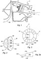
- FIG. 1 there is shown a portion of a turbojet engine 2 extending in an axial direction 100 and equipped with a combustion chamber 10 and with a centrifugal high pressure compressor output.
- This combustion chamber 10 comprises an outer wall 12 and an inner wall 14, which are coaxial and substantially frustoconical, and which flare from downstream upstream with a cone angle ⁇ substantially between 25 and 35 degrees.
- the combustion chamber 10 is comprised in a diffusion chamber 30 which is an annular space defined between an outer casing 32 and an inner casing 34, into which a compressed oxidant originating upstream of a compressor (not shown) by the compressor is introduced.
- the intermediate end of an annular diffusion duct 36 Because of the inclination of the combustion chamber 10, the upstream end thereof is radially further out than the downstream end thereof.
- the outer 12 and inner walls 14 of the combustion chamber 10 are connected to each other upstream of the combustion chamber by a chamber bottom 16, which is a substantially annular and frustoconical piece extending between two substantially transverse planes. flaring from upstream to downstream.
- the chamber bottom 16 is connected to each of the two outer 12 and inner 14 walls of the combustion chamber 10. It is provided with injection openings 18 through which injection systems 20 pass through the outer casing 32. and which introduce fuel to the upstream end of the combustion chamber 10 where the combustion reactions take place.
- the figure 2 shows schematically and in perspective a chamber bottom 16, which is a substantially frustoconical part, the axis 160 is coincident, in use, with the axis of the turbojet.
- the chamber bottom 16 has an upstream edge 162 and a downstream edge 164. It widens from the upstream edge 162 to the downstream edge 164. It is in the form of a frustoconical envelope having an inner face 80 and an outer face 82.
- the body of the chamber bottom is not continuously curved, but has flat portions 166, or facets, successive and adjacent. A flat portion 166 is shown in plan view at the figure 2a .
- It has a contour having four sides 172, 174, 176, 178 which is supported on an angular sector from a point 170.
- Two of the sides 172, 176 are concentric arcs and centered on the point 170.
- Both other sides 174, 178 are line segments from point 170 and resting on the angular sector, which connect the two circular arcs 172, 176.
- the figure 3 is a schematic representation of the same chamber bottom 16, seen in plan view from the downstream, as indicated by the arrow III of the figure 2 .
- the flat portions 166 which are regularly distributed on the body of the chamber bottom 16 between its upstream edge 162 and its downstream edge 164.
- the figure 4 is a partial view similar to the figure 3 more realistically showing a chamber bottom portion 16 seen in plan view from downstream.
- the chamber bottom has injection openings 18 formed through each of the flat portions 166. These injection openings 18 serve to pass the injection systems 20 already described with reference to FIG. figure 1 .
- Each injection opening 18 is substantially centered on the corresponding flat portion 166.
- the chamber floor 16 comprises ribs 40, which extend from its upstream edge 162 to its downstream edge 164, in a direction substantially rectilinear and perpendicular to said edges 162, 164. These ribs 40 form recesses on the inner face 80 of the chamber bottom 16 and bosses on its outer face 82.
- the ribs 40 have a substantially rectangular shape and have a relatively small thickness which can vary from 0 to 2 or 3 mm. They do not extend to each of the two upstream edges 162 and downstream 164, but stop slightly before them, at a distance substantially between 0.5 and 2 mm.
- the chamber bottom 16 has cooling orifices 24, the function of which will be described in more detail below. In the example shown, the cooling orifices 24 are aligned on either side of each rib 40 and are four in number on each side of each rib 40.
- the figure 5 is a view of the chamber bottom 16, in section along the plane VV of the figure 3 .
- This view shows the flat portions 166, and at the junction between the latter, the bosses formed by the ribs 40 on the outer face 82 of the chamber bottom 16.
- On each side of each rib 40 appear the cooling orifices 24 which are formed through the flat portions 166.
- the figure 5 also shows deflectors 22, which are substantially flat plates fixed on the chamber bottom 16. These baffles comprise lateral flanges 222 which each engage in one of the two ribs 40 which border the flat portion 166 receiving the deflector 22. The cooperation of these side flanges 222 with said ribs 40 avoids lateral leakage.
- Each deflector 22 also comprises a substantially central hole 226 facing the injection opening 18 of the flat portion 166 receiving the deflector 22, to allow the corresponding injection system 20 to pass (see FIG. figure 1 ).
- these central holes 226 are holes having fallen edges 224.
- the fixing of the deflectors 22 on the chamber bottom 16 is preferably made by brazing at the central holes 226.
- the distance D which separates each deflector 22 from the flat portion 166 which receives it remains constant, and the cooling of the deflectors 22 can be satisfactorily performed.
- the cooling is materialized to the right of the figure 5 by an arrow 44 which represents an air jet coming from upstream and passing through the cooling orifices 24 of a flat portion 166 of the chamber bottom 16, in order to impact the deflector 22 fixed on this flat portion 166.
- the embodiment of the chamber bottom 16 implements at least one pressure deformation operation and several drilling operations. It starts from a frustoconical piece of revolution that is deformed by a stamping operation to transform the body of the truncated cone into a succession of planar portions adjacent to each other. During this stamping operation, ribs are also formed between the planar portions.
- Drilling operations are then performed consisting of piercing injection openings substantially in the center of each flat portion, and piercing cooling orifices distributed in each flat portion and along each rib.
- the cooling orifices are pierced on each side of each rib.
- the number and positions of the cooling orifices are not limited.
Landscapes
- Engineering & Computer Science (AREA)
- Chemical & Material Sciences (AREA)
- Combustion & Propulsion (AREA)
- Mechanical Engineering (AREA)
- General Engineering & Computer Science (AREA)
- Turbine Rotor Nozzle Sealing (AREA)
- Structures Of Non-Positive Displacement Pumps (AREA)
- Cylinder Crankcases Of Internal Combustion Engines (AREA)
Claims (14)
- Ringförmige Brennkammer (10) eines Turbostrahltriebwerks (2), die durch eine äußere Wand (12) und eine innere Wand (14) begrenzt ist, wobei die äußere (12) und innere (14) Wand kegelstumpfförmig sind, und wobei die äußere (12) und innere (14) Wand vorne durch eine Wand verbunden sind, die einen Kammerboden (16) bildet, umfassend mehrere Abweiser (22), die die Form von ebenen Platten aufweisen, die auf einer Fläche (80) des Kammerbodens (16) befestigt sind, die dem Inneren der Verbrennungskammer (10) gegenüberliegt, wobei der Kammerboden (16), der sich von vorn nach hinten aufweitet, die Form eines im Wesentlichen kegelstumpfförmigen Teils aufweist und dadurch gekennzeichnet ist, dass er durch eine Abfolge von benachbarten ebenen Abschnitten (166) gebildet ist.
- Brennkammer (10) nach Anspruch 1, wobei jeder ebene Abschnitt (166) des Brennkammerbodens eine Kontur aufweist, die sich auf einen Winkelsektor stützt, dessen zwei Seiten (174, 178) Liniensegmente sind, die aus einem gleichen vorderen Zentrum (170) stammen.
- Brennkammer (10) nach Anspruch 2, wobei die Kontur des ebenen Abschnitts (166) vier Seiten (172, 174, 176, 178) aufweist, wovon zwei Seiten (172, 176) konzentrische Kreisbögen des gleichen Zentrums (170) sind, und wovon die zwei anderen Seiten (174, 178) Liniensegmente sind, die aus dem Zentrum (170) stammen und die diese zwei Kreisbögen (172, 176) verbinden.
- Brennkammer (10) nach einem der Ansprüche 1 bis 3, wobei mindestens einer der ebenen Abschnitte (166) von einer Einspritzöffnung (18) durchquert ist.
- Brennkammer (10) nach einem der Ansprüche 1 bis 4, umfassend Rippen (40), die sich radial zwischen den ebenen Abschnitte (166) erstrecken.
- Brennkammer (10) nach Anspruch 5, umfassend Kühlöffnungen (24) entlang der Rippen (40).
- Brennkammer (10) nach Anspruch 6, wobei sich die Kühlöffnungen (24) entlang zweier radialer Linien erstrecken, die auf jeder Seite von jeder Rippe (40) angeordnet sind.
- Brennkammer (10) nach Anspruch 1, dadurch gekennzeichnet, dass sie Abweiser (22) aufweist, die die Form von im Wesentlichen ebenen Platten aufweisen, wobei die Anzahl der Abweiser (22) gleich der Anzahl der ebenen Abschnitte (166) des Kammerbodens (16) ist, und dass jeder Abweiser (22) an einem der ebenen Abschnitte (166) auf einer Fläche (80) befestigt ist, die dem Inneren der Brennkammer (10) gegenüberliegt.
- Brennkammer (10) nach Anspruch 8, wobei die Abweiser (22) seitliche Ränder (222) aufweisen, die mit den Rippen (40) zusammenwirken, um seitliche Undichtigkeiten zu vermeiden.
- Turbostrahltriebwerk (2), dadurch gekennzeichnet, dass es eine Brennkammer (10) nach einem der Ansprüche 1 bis 9 aufweist.
- Verfahren zur Herstellung einer Brennkammer nach einem der Ansprüche 1 bis 7, dadurch gekennzeichnet, dass es mindestens einen Tiefziehvorgang aufweist, der einen Kammerboden, der ursprünglich eben ist, verformt, um ebene Abschnitte (166) zu erstellen.
- Verfahren nach Anspruch 11, dadurch gekennzeichnet, dass es mindestens einen Bohrvorgang aufweist, um eine Einspritzöffnung (18) durch mindestens einen ebenen Abschnitt (166) zu erstellen.
- Verfahren nach Anspruch 11 oder 12, dadurch gekennzeichnet, dass der Tiefziehvorgang Rippen (40) zwischen den ebenen Abschnitten (166) erstellt.
- Verfahren nach Anspruch 13, dadurch gekennzeichnet, dass es mindestens einen Bohrvorgang aufweist, um Kühlöffnungen (24) entlang der Rippen (40) zu erstellen.
Applications Claiming Priority (1)
| Application Number | Priority Date | Filing Date | Title |
|---|---|---|---|
| FR0655377A FR2909748B1 (fr) | 2006-12-07 | 2006-12-07 | Fond de chambre, procede de realisation de celui-ci, chambre de combustion le comportant et turboreacteur en etant equipe |
Publications (2)
| Publication Number | Publication Date |
|---|---|
| EP1930659A1 EP1930659A1 (de) | 2008-06-11 |
| EP1930659B1 true EP1930659B1 (de) | 2017-06-07 |
Family
ID=38222462
Family Applications (1)
| Application Number | Title | Priority Date | Filing Date |
|---|---|---|---|
| EP07122642.7A Active EP1930659B1 (de) | 2006-12-07 | 2007-12-07 | Brennkammer eines Turbostrahltriebwerks |
Country Status (6)
| Country | Link |
|---|---|
| US (1) | US7954327B2 (de) |
| EP (1) | EP1930659B1 (de) |
| JP (1) | JP4974295B2 (de) |
| CA (1) | CA2613268C (de) |
| FR (1) | FR2909748B1 (de) |
| RU (1) | RU2435108C2 (de) |
Families Citing this family (8)
| Publication number | Priority date | Publication date | Assignee | Title |
|---|---|---|---|---|
| FR2918443B1 (fr) * | 2007-07-04 | 2009-10-30 | Snecma Sa | Chambre de combustion comportant des deflecteurs de protection thermique de fond de chambre et moteur a turbine a gaz en etant equipe |
| FR2920525B1 (fr) * | 2007-08-31 | 2014-06-13 | Snecma | Separateur pour alimentation de l'air de refroidissement d'une turbine |
| FR2921462B1 (fr) * | 2007-09-21 | 2012-08-24 | Snecma | Chambre de combustion annulaire de moteur a turbine a gaz |
| FR2948988B1 (fr) | 2009-08-04 | 2011-12-09 | Snecma | Chambre de combustion de turbomachine comprenant des orifices d'entree d'air ameliores |
| DE102010023816A1 (de) * | 2010-06-15 | 2011-12-15 | Rolls-Royce Deutschland Ltd & Co Kg | Gasturbinenbrennkammeranordnung |
| DE102011108887A1 (de) | 2011-07-28 | 2013-01-31 | Rolls-Royce Deutschland Ltd & Co Kg | Gasturbinenzentripetalringbrennkammer sowie Verfahren zur Strömungsführung |
| FR2982010B1 (fr) * | 2011-10-26 | 2013-11-08 | Snecma | Chambre de combustion annulaire dans une turbomachine |
| US10234141B2 (en) * | 2016-04-28 | 2019-03-19 | United Technoloigies Corporation | Ceramic and ceramic matrix composite attachment methods and systems |
Citations (3)
| Publication number | Priority date | Publication date | Assignee | Title |
|---|---|---|---|---|
| US2560207A (en) | 1948-02-04 | 1951-07-10 | Wright Aeronautical Corp | Annular combustion chamber with circumferentially spaced double air-swirl burners |
| US2560223A (en) | 1948-02-04 | 1951-07-10 | Wright Aeronautical Corp | Double air-swirl baffle construction for fuel burners |
| US5581999A (en) | 1994-12-15 | 1996-12-10 | United Technologies Corporation | Bulkhead liner with raised lip |
Family Cites Families (28)
| Publication number | Priority date | Publication date | Assignee | Title |
|---|---|---|---|---|
| GB774592A (en) * | 1954-05-18 | 1957-05-15 | Havilland Engine Co Ltd | Adjustable propulsion nozzles |
| US4454711A (en) * | 1981-10-29 | 1984-06-19 | Avco Corporation | Self-aligning fuel nozzle assembly |
| US4567730A (en) * | 1983-10-03 | 1986-02-04 | General Electric Company | Shielded combustor |
| US4843825A (en) * | 1988-05-16 | 1989-07-04 | United Technologies Corporation | Combustor dome heat shield |
| US4914918A (en) * | 1988-09-26 | 1990-04-10 | United Technologies Corporation | Combustor segmented deflector |
| US4934145A (en) * | 1988-10-12 | 1990-06-19 | United Technologies Corporation | Combustor bulkhead heat shield assembly |
| FR2673454B1 (fr) * | 1991-02-28 | 1995-01-13 | Snecma | Chambre de combustion comportant une paroi de fond comprenant une pluralite de troncs de cones partiels. |
| US5289687A (en) * | 1992-03-30 | 1994-03-01 | General Electric Company | One-piece cowl for a double annular combustor |
| US5419115A (en) * | 1994-04-29 | 1995-05-30 | United Technologies Corporation | Bulkhead and fuel nozzle guide assembly for an annular combustion chamber |
| DE4427222A1 (de) * | 1994-08-01 | 1996-02-08 | Bmw Rolls Royce Gmbh | Hitzeschild für eine Gasturbinen-Brennkammer |
| US6070830A (en) * | 1997-09-29 | 2000-06-06 | General Electric Company | Faceted exhaust nozzle |
| US6438958B1 (en) * | 2000-02-28 | 2002-08-27 | General Electric Company | Apparatus for reducing heat load in combustor panels |
| US6557349B1 (en) * | 2000-04-17 | 2003-05-06 | General Electric Company | Method and apparatus for increasing heat transfer from combustors |
| US6546733B2 (en) * | 2001-06-28 | 2003-04-15 | General Electric Company | Methods and systems for cooling gas turbine engine combustors |
| US6792757B2 (en) * | 2002-11-05 | 2004-09-21 | Honeywell International Inc. | Gas turbine combustor heat shield impingement cooling baffle |
| US7121095B2 (en) * | 2003-08-11 | 2006-10-17 | General Electric Company | Combustor dome assembly of a gas turbine engine having improved deflector plates |
| US7093441B2 (en) * | 2003-10-09 | 2006-08-22 | United Technologies Corporation | Gas turbine annular combustor having a first converging volume and a second converging volume, converging less gradually than the first converging volume |
| US7051532B2 (en) * | 2003-10-17 | 2006-05-30 | General Electric Company | Methods and apparatus for film cooling gas turbine engine combustors |
| US7506511B2 (en) * | 2003-12-23 | 2009-03-24 | Honeywell International Inc. | Reduced exhaust emissions gas turbine engine combustor |
| US6983599B2 (en) * | 2004-02-12 | 2006-01-10 | General Electric Company | Combustor member and method for making a combustor assembly |
| US7140185B2 (en) * | 2004-07-12 | 2006-11-28 | United Technologies Corporation | Heatshielded article |
| FR2888631B1 (fr) * | 2005-07-18 | 2010-12-10 | Snecma | Turbomachine a distribution angulaire de l'air |
| FR2897145B1 (fr) * | 2006-02-08 | 2013-01-18 | Snecma | Chambre de combustion annulaire de turbomachine a fixations alternees. |
| FR2897417A1 (fr) * | 2006-02-10 | 2007-08-17 | Snecma Sa | Chambre de combustion annulaire d'une turbomachine |
| US8596071B2 (en) * | 2006-05-05 | 2013-12-03 | General Electric Company | Method and apparatus for assembling a gas turbine engine |
| CN101657682B (zh) * | 2006-09-14 | 2011-06-15 | 索拉透平公司 | 用于涡轮发动机的挡溅板拱座组件 |
| US7665306B2 (en) * | 2007-06-22 | 2010-02-23 | Honeywell International Inc. | Heat shields for use in combustors |
| US20100095680A1 (en) * | 2008-10-22 | 2010-04-22 | Honeywell International Inc. | Dual wall structure for use in a combustor of a gas turbine engine |
-
2006
- 2006-12-07 FR FR0655377A patent/FR2909748B1/fr active Active
-
2007
- 2007-11-27 US US11/945,580 patent/US7954327B2/en active Active
- 2007-11-28 JP JP2007307112A patent/JP4974295B2/ja active Active
- 2007-12-05 CA CA2613268A patent/CA2613268C/fr active Active
- 2007-12-06 RU RU2007145372/06A patent/RU2435108C2/ru active
- 2007-12-07 EP EP07122642.7A patent/EP1930659B1/de active Active
Patent Citations (3)
| Publication number | Priority date | Publication date | Assignee | Title |
|---|---|---|---|---|
| US2560207A (en) | 1948-02-04 | 1951-07-10 | Wright Aeronautical Corp | Annular combustion chamber with circumferentially spaced double air-swirl burners |
| US2560223A (en) | 1948-02-04 | 1951-07-10 | Wright Aeronautical Corp | Double air-swirl baffle construction for fuel burners |
| US5581999A (en) | 1994-12-15 | 1996-12-10 | United Technologies Corporation | Bulkhead liner with raised lip |
Also Published As
| Publication number | Publication date |
|---|---|
| FR2909748B1 (fr) | 2009-07-10 |
| JP4974295B2 (ja) | 2012-07-11 |
| CA2613268A1 (fr) | 2008-06-07 |
| US20080134661A1 (en) | 2008-06-12 |
| US7954327B2 (en) | 2011-06-07 |
| RU2435108C2 (ru) | 2011-11-27 |
| CA2613268C (fr) | 2015-02-03 |
| FR2909748A1 (fr) | 2008-06-13 |
| EP1930659A1 (de) | 2008-06-11 |
| RU2007145372A (ru) | 2009-06-20 |
| JP2008145098A (ja) | 2008-06-26 |
Similar Documents
| Publication | Publication Date | Title |
|---|---|---|
| EP1930659B1 (de) | Brennkammer eines Turbostrahltriebwerks | |
| EP2071242B1 (de) | Vorrichtung zum Einspritzen eines Gemisches aus Luft und Brennstoff in eine Brennkammer eines Turbotriebwerks | |
| EP2012061B2 (de) | Brennkammer eines Gasturbinentriebwerks | |
| EP2678610B1 (de) | Ringförmige brennkammer für eine turbinenmaschine mit verbesserten verdünnungsöffnungen | |
| FR2751054A1 (fr) | Chambre de combustion anti-nox a injection de carburant de type annulaire | |
| EP1939528B1 (de) | Deflektor für rückwärtigen Teil der Brennkammer, damit ausgestattete Brennkammer und Turbostrahltriebwerk, das beide umfasst | |
| EP2409085B1 (de) | Turbomotorbrennkammer mit einer verbesserten primärluft-zufuhreinrichtung | |
| FR2930591A1 (fr) | Optimisation du positionnement angulaire d'un distributeur de turbine en sortie d'une chambre de combustion de turbomachine | |
| EP3569929A1 (de) | Einheit für eine brennkammer eines turbotriebwerks | |
| FR3087847A1 (fr) | Melangeur a lobes favorisant le melange de flux confluents | |
| EP3039342B1 (de) | Gasturbinenverbrennungskammer mit homogenem lufteinlass durch die brennstoffeinspritzungsvorrichtungen | |
| EP3530908B1 (de) | Brennkammer, die zwei typen von injektoren umfasst, in denen die dichtungsorgane eine unterschiedliche öffnungsschwelle besitzen | |
| EP2040001A2 (de) | Ringförmige Brennkammer eines Gasturbinenmotors | |
| EP2705219B1 (de) | Turbinendüsenleitschaufelanordnung in einer turbomaschine | |
| EP3449185B1 (de) | Turbomaschineneinspritzsystem mit einem aerodynamischen deflektor an seinem einlass und einem lufteinlassverwirbler | |
| EP4179256B1 (de) | Ringbrennkammer für eine flugzeugturbomaschine | |
| EP4042070B1 (de) | Vorverdampfungsrohr für die brennkammer eines turbinenmotors | |
| FR2978200A1 (fr) | Diffuseur d'echappement de turbine basse pression avec turbulateurs | |
| FR2999277A1 (fr) | Paroi annulaire de chambre de combustion en aval d'un compresseur centrifuge | |
| WO2025242981A1 (fr) | Injecteur ondulé de dispositif d'injection pour chambre de combustion | |
| EP4327022A1 (de) | Kraftstoffeinspritzvorrichtung für nachbrenner eines turbostrahltriebwerks | |
| FR3022597A1 (fr) | Diffuseur a triple flux pour module de turbomachine comprenant des dispositifs de canalisation d'air entre les deux parois de separation du diffuseur |
Legal Events
| Date | Code | Title | Description |
|---|---|---|---|
| PUAI | Public reference made under article 153(3) epc to a published international application that has entered the european phase |
Free format text: ORIGINAL CODE: 0009012 |
|
| 17P | Request for examination filed |
Effective date: 20071207 |
|
| AK | Designated contracting states |
Kind code of ref document: A1 Designated state(s): AT BE BG CH CY CZ DE DK EE ES FI FR GB GR HU IE IS IT LI LT LU LV MC MT NL PL PT RO SE SI SK TR |
|
| AX | Request for extension of the european patent |
Extension state: AL BA HR MK RS |
|
| AKX | Designation fees paid |
Designated state(s): DE FR GB IT |
|
| RAP1 | Party data changed (applicant data changed or rights of an application transferred) |
Owner name: SNECMA |
|
| RAP1 | Party data changed (applicant data changed or rights of an application transferred) |
Owner name: SAFRAN AIRCRAFT ENGINES |
|
| GRAP | Despatch of communication of intention to grant a patent |
Free format text: ORIGINAL CODE: EPIDOSNIGR1 |
|
| STAA | Information on the status of an ep patent application or granted ep patent |
Free format text: STATUS: GRANT OF PATENT IS INTENDED |
|
| INTG | Intention to grant announced |
Effective date: 20161213 |
|
| GRAJ | Information related to disapproval of communication of intention to grant by the applicant or resumption of examination proceedings by the epo deleted |
Free format text: ORIGINAL CODE: EPIDOSDIGR1 |
|
| STAA | Information on the status of an ep patent application or granted ep patent |
Free format text: STATUS: REQUEST FOR EXAMINATION WAS MADE |
|
| GRAS | Grant fee paid |
Free format text: ORIGINAL CODE: EPIDOSNIGR3 |
|
| STAA | Information on the status of an ep patent application or granted ep patent |
Free format text: STATUS: GRANT OF PATENT IS INTENDED |
|
| GRAP | Despatch of communication of intention to grant a patent |
Free format text: ORIGINAL CODE: EPIDOSNIGR1 |
|
| INTC | Intention to grant announced (deleted) | ||
| INTG | Intention to grant announced |
Effective date: 20170222 |
|
| GRAA | (expected) grant |
Free format text: ORIGINAL CODE: 0009210 |
|
| STAA | Information on the status of an ep patent application or granted ep patent |
Free format text: STATUS: THE PATENT HAS BEEN GRANTED |
|
| AK | Designated contracting states |
Kind code of ref document: B1 Designated state(s): DE FR GB IT |
|
| REG | Reference to a national code |
Ref country code: GB Ref legal event code: FG4D Free format text: NOT ENGLISH |
|
| GRAA | (expected) grant |
Free format text: ORIGINAL CODE: 0009210 |
|
| REG | Reference to a national code |
Ref country code: DE Ref legal event code: R096 Ref document number: 602007051227 Country of ref document: DE |
|
| REG | Reference to a national code |
Ref country code: FR Ref legal event code: PLFP Year of fee payment: 11 |
|
| REG | Reference to a national code |
Ref country code: DE Ref legal event code: R026 Ref document number: 602007051227 Country of ref document: DE |
|
| PLBI | Opposition filed |
Free format text: ORIGINAL CODE: 0009260 |
|
| PLAX | Notice of opposition and request to file observation + time limit sent |
Free format text: ORIGINAL CODE: EPIDOSNOBS2 |
|
| 26 | Opposition filed |
Opponent name: UNITED TECHNOLOGIES CORPORATION Effective date: 20180307 |
|
| PLAB | Opposition data, opponent's data or that of the opponent's representative modified |
Free format text: ORIGINAL CODE: 0009299OPPO |
|
| R26 | Opposition filed (corrected) |
Opponent name: UNITED TECHNOLOGIES CORPORATION Effective date: 20180307 |
|
| PLBB | Reply of patent proprietor to notice(s) of opposition received |
Free format text: ORIGINAL CODE: EPIDOSNOBS3 |
|
| REG | Reference to a national code |
Ref country code: DE Ref legal event code: R100 Ref document number: 602007051227 Country of ref document: DE |
|
| PLCK | Communication despatched that opposition was rejected |
Free format text: ORIGINAL CODE: EPIDOSNREJ1 |
|
| PLBN | Opposition rejected |
Free format text: ORIGINAL CODE: 0009273 |
|
| STAA | Information on the status of an ep patent application or granted ep patent |
Free format text: STATUS: OPPOSITION REJECTED |
|
| 27O | Opposition rejected |
Effective date: 20190617 |
|
| PGFP | Annual fee paid to national office [announced via postgrant information from national office to epo] |
Ref country code: GB Payment date: 20251229 Year of fee payment: 19 |
|
| PGFP | Annual fee paid to national office [announced via postgrant information from national office to epo] |
Ref country code: FR Payment date: 20251222 Year of fee payment: 19 |
|
| PGFP | Annual fee paid to national office [announced via postgrant information from national office to epo] |
Ref country code: DE Payment date: 20251222 Year of fee payment: 19 |
|
| PGFP | Annual fee paid to national office [announced via postgrant information from national office to epo] |
Ref country code: IT Payment date: 20251231 Year of fee payment: 19 |