EP1930798A2 - Flussregelvorrichtung - Google Patents
Flussregelvorrichtung Download PDFInfo
- Publication number
- EP1930798A2 EP1930798A2 EP06024792A EP06024792A EP1930798A2 EP 1930798 A2 EP1930798 A2 EP 1930798A2 EP 06024792 A EP06024792 A EP 06024792A EP 06024792 A EP06024792 A EP 06024792A EP 1930798 A2 EP1930798 A2 EP 1930798A2
- Authority
- EP
- European Patent Office
- Prior art keywords
- hot
- valve
- outlet
- water
- bypass
- Prior art date
- Legal status (The legal status is an assumption and is not a legal conclusion. Google has not performed a legal analysis and makes no representation as to the accuracy of the status listed.)
- Withdrawn
Links
- XLYOFNOQVPJJNP-UHFFFAOYSA-N water Substances O XLYOFNOQVPJJNP-UHFFFAOYSA-N 0.000 claims abstract description 76
- 238000005496 tempering Methods 0.000 claims abstract description 13
- 239000002699 waste material Substances 0.000 abstract description 3
- 238000010586 diagram Methods 0.000 description 5
- 238000007792 addition Methods 0.000 description 3
- 238000003973 irrigation Methods 0.000 description 2
- 230000002262 irrigation Effects 0.000 description 2
- 230000004048 modification Effects 0.000 description 2
- 238000012986 modification Methods 0.000 description 2
- 238000009428 plumbing Methods 0.000 description 2
- 239000002023 wood Substances 0.000 description 2
- 241000894006 Bacteria Species 0.000 description 1
- 229920005549 butyl rubber Polymers 0.000 description 1
- 238000004140 cleaning Methods 0.000 description 1
- 238000001816 cooling Methods 0.000 description 1
- 229920001971 elastomer Polymers 0.000 description 1
- 230000005484 gravity Effects 0.000 description 1
- 238000010438 heat treatment Methods 0.000 description 1
- 238000009434 installation Methods 0.000 description 1
- 238000009413 insulation Methods 0.000 description 1
- 239000007788 liquid Substances 0.000 description 1
- 229920002635 polyurethane Polymers 0.000 description 1
- 239000004814 polyurethane Substances 0.000 description 1
- 238000011084 recovery Methods 0.000 description 1
Images



Classifications
-
- G—PHYSICS
- G05—CONTROLLING; REGULATING
- G05D—SYSTEMS FOR CONTROLLING OR REGULATING NON-ELECTRIC VARIABLES
- G05D23/00—Control of temperature
- G05D23/01—Control of temperature without auxiliary power
- G05D23/13—Control of temperature without auxiliary power by varying the mixing ratio of two fluids having different temperatures
- G05D23/1306—Control of temperature without auxiliary power by varying the mixing ratio of two fluids having different temperatures for liquids
- G05D23/132—Control of temperature without auxiliary power by varying the mixing ratio of two fluids having different temperatures for liquids with temperature sensing element
- G05D23/134—Control of temperature without auxiliary power by varying the mixing ratio of two fluids having different temperatures for liquids with temperature sensing element measuring the temperature of mixed fluid
- G05D23/136—Control of temperature without auxiliary power by varying the mixing ratio of two fluids having different temperatures for liquids with temperature sensing element measuring the temperature of mixed fluid with pressure equalizing means
Definitions
- This invention concerns devices for delivering a liquid stream at a predetermined temperature.
- the invention will be described with particular reference to supplying hot water facilities in buildings and saving water in dwellings which have a hot water service.
- the bypass may direct cold water to a collector at the same water pressure as the supply pressure. In gas or other water heating installations this will be mains pressure, namely greater than 400kPa. Such a feed pressure will send water a useful distance in an urban setting, for example a pool, a garden watering system, or storage tank. On rural properties the supply pressure will not have mains pressure but pump pressure or pressure created by a gravity feed header tank. The cold outlet may therefore return water to the storage tank for re-use.
- WO2004088051 describes a water recovery system in which bypass water is diverted by a valve assembly until it is sufficiently hot and a venturi situated between the mains inlet and the mains outlet "sucks in” bypassed water from a storage tank and returns it to the system.
- the aim of this invention is not to capture bypass water, but to make it available for use rather than running it to waste.
- a valve assembly comprising
- the thermostatic valve may be a wax element tempering valve connected for reverse operation.
- the diaphragm valve may be connected by capillary conduit to the hot outlet.
- inlet/outlet connections of the assembly may be substantially aligned and all point in the same direction.
- the hot inlet of the assembly may be connected to the hot inlet of a basin and the hot outlet may be connected to conduits which service other hot water outlets in the vicinity including the hot tap supplying the basin while the bypass water is collected. Accordingly the assembly may be fitted in the basin cabinet and plumbed into the other outlets in the bathroom such as the shower or bath. It may also be placed in any location adjacent to the multiple outlets to be supplied.
- the hot outlet of the assembly is connected to the hot inlet of a tempering valve which has a cold inlet for cooling the hot flow and an outlet for tempered flow.
- the tempering valve may be adjustable to deliver tempered flow at 44°C. Placing the assembly in a basin cabinet allows access for repair and adjustment.
- gas/electric/oil/wood/other heater 2 receives a cold water supply 4 at mains pressure and through the wall via pipe 6.
- Hot water main 8 travels across the dwelling to washbasin 12.
- Hot main 8 supplies bypass component 12.
- Bypassed cold water leaves component 12 through pipe 14 which joins a drip irrigation system or other (not shown).
- Hot outlet 16 serves basin tap 18 and shower 20. Screw valve 22 in the shower controls shower flow in known manner.
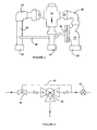
- component 12 has three unions 24, 26, 28.
- Union 24 admits hot water from hot water main 8 to the outlet of a thermostatic valve 30 against the flow direction marked with the arrow.
- the valve contains a wax element and is a standard plumbing component.
- the COLD side marked “C” is connected to a bend 32 and a stub 34 which ends in union 26.
- the HOT side marked “H” is connected via bend 36 to diaphragm valve 38 which is also a standard plumbing component.
- diaphragm valve 38 which is also a standard plumbing component.
- One side of the diaphragm is connected by capillary tube 40 to stub 34.
- the cold bypass water leaves union 28. to join pipe 14.
- valve 42 when the user opens valve 42, water from the heater issues at varying temperature and pressure. If the wax element is not thermally activated, water enters at port A and leaves via port B to bypass. C is adjusted to open above a target temperature. As the arriving water rises in temperature, the wax element closes port B and opens port C. When valve 42 closes, pressure rises at port C via the capillary tube and the diaphragm valve closes and remains closed until valve 42 reopens.
- FIG 4 an assembly is shown which uses mains hot and cold water and bypasses water during the warm up period.
- the assembly is intended to deliver hot water at a uniform temperature.
- the bypass component 12 receives flow at 50°C or greater from hot main 8.
- Cold and warm water leave the assembly through bypass 14.
- Hot water leaves component 12 through stub 34 and enters tempering valve 44.
- Cold main 4 supplies sufficient flow to reduce the temperature by a few degrees.
- the hot flow is delivered by tempering valve 44 at 44°C.
- the tempering valve is connected to hot and cold flows the conventional way round.
- FIG 5 shows an alternative configuration to the Figure 4 assembly.
- the thermostatic valve 30 and diaphragm valve are arranged as in Figure 4 but there are four unions.
- gas/electric/oil/wood/other heater 2 receives a cold water supply 4 at mains pressure and through the wall via pipe 6.
- Hot water main 8 travels across the dwelling to washbasin 10.
- Hot main 8 supplies bypass component 12.
- Bypassed cold water leaves component 12 through pipe 14 which joins a drip irrigation system or other (not shown).
- Cold water from main 6 enters temperature control module 44 where it is mixed with hot water from 12 which is delivered to pipe 16 at target temperature of 44°C approximately to serve basin 18, shower 22 and bath 24 via screw valves to control water flow in known manner.
Landscapes
- Physics & Mathematics (AREA)
- General Physics & Mathematics (AREA)
- Engineering & Computer Science (AREA)
- Automation & Control Theory (AREA)
- Domestic Hot-Water Supply Systems And Details Of Heating Systems (AREA)
Priority Applications (1)
| Application Number | Priority Date | Filing Date | Title |
|---|---|---|---|
| EP06024792A EP1930798A2 (de) | 2006-11-30 | 2006-11-30 | Flussregelvorrichtung |
Applications Claiming Priority (1)
| Application Number | Priority Date | Filing Date | Title |
|---|---|---|---|
| EP06024792A EP1930798A2 (de) | 2006-11-30 | 2006-11-30 | Flussregelvorrichtung |
Publications (1)
| Publication Number | Publication Date |
|---|---|
| EP1930798A2 true EP1930798A2 (de) | 2008-06-11 |
Family
ID=39278965
Family Applications (1)
| Application Number | Title | Priority Date | Filing Date |
|---|---|---|---|
| EP06024792A Withdrawn EP1930798A2 (de) | 2006-11-30 | 2006-11-30 | Flussregelvorrichtung |
Country Status (1)
| Country | Link |
|---|---|
| EP (1) | EP1930798A2 (de) |
Citations (1)
| Publication number | Priority date | Publication date | Assignee | Title |
|---|---|---|---|---|
| WO2004088051A1 (en) | 2003-04-02 | 2004-10-14 | Innovative Environmental Solutions Pty Ltd | Water recovery systems and control valves |
-
2006
- 2006-11-30 EP EP06024792A patent/EP1930798A2/de not_active Withdrawn
Patent Citations (1)
| Publication number | Priority date | Publication date | Assignee | Title |
|---|---|---|---|---|
| WO2004088051A1 (en) | 2003-04-02 | 2004-10-14 | Innovative Environmental Solutions Pty Ltd | Water recovery systems and control valves |
Similar Documents
| Publication | Publication Date | Title |
|---|---|---|
| AU2018280129B2 (en) | Recirculating fluid heating systems | |
| US5331996A (en) | Dual mode hot water circulation apparatus | |
| US7773868B2 (en) | Method and system for recirculating hot water | |
| US5872891A (en) | System for providing substantially instantaneous hot water | |
| RU2449220C2 (ru) | Устройство для распределения воды с различной температурой | |
| US5518022A (en) | Aspirator water circulation apparatus | |
| US9255644B1 (en) | Prompt hot water and water conservation system and method | |
| US20060289065A1 (en) | Rapid hot water apparatus and method | |
| US20100263604A1 (en) | Water heater with passive automatic hot water circulation through a home or building | |
| AU2010338399B2 (en) | Pressure enhancing device | |
| US5671771A (en) | Hot water system | |
| US11112126B2 (en) | Method and device for saving heat energy and water in a sanitary facility | |
| CA2485010C (en) | Temperate water supply system | |
| US20090165875A1 (en) | Assembly for saving water | |
| US20090288715A1 (en) | Hot water recirculator using piping venturi | |
| US20080128521A1 (en) | Flow Control Device | |
| US6164307A (en) | Non-circulating, rapid, hot tap water apparatus and method | |
| US20050166313A1 (en) | Insulated hot water storage tank for sink | |
| AU2006202441A1 (en) | Flow control device | |
| CN101788163A (zh) | 一种带储水箱的热水器及其供水系统 | |
| RU2188359C1 (ru) | Квартирная система отопления | |
| US11118813B2 (en) | Tankless water heater and manifold system | |
| AU2007100748A4 (en) | OZCIRC - A Methodology to Save Water & Energy | |
| IL199687A (en) | Heated water recirculation system | |
| KR100634112B1 (ko) | 수용기기장착 배관방법 |
Legal Events
| Date | Code | Title | Description |
|---|---|---|---|
| PUAI | Public reference made under article 153(3) epc to a published international application that has entered the european phase |
Free format text: ORIGINAL CODE: 0009012 |
|
| AK | Designated contracting states |
Kind code of ref document: A2 Designated state(s): AT BE BG CH CY CZ DE DK EE ES FI FR GB GR HU IE IS IT LI LT LU LV MC NL PL PT RO SE SI SK TR |
|
| AX | Request for extension of the european patent |
Extension state: AL BA HR MK RS |
|
| STAA | Information on the status of an ep patent application or granted ep patent |
Free format text: STATUS: THE APPLICATION IS DEEMED TO BE WITHDRAWN |
|
| 18D | Application deemed to be withdrawn |
Effective date: 20090603 |