EP1930985A2 - Elektrischer Steckverbinder - Google Patents
Elektrischer Steckverbinder Download PDFInfo
- Publication number
- EP1930985A2 EP1930985A2 EP07122430A EP07122430A EP1930985A2 EP 1930985 A2 EP1930985 A2 EP 1930985A2 EP 07122430 A EP07122430 A EP 07122430A EP 07122430 A EP07122430 A EP 07122430A EP 1930985 A2 EP1930985 A2 EP 1930985A2
- Authority
- EP
- European Patent Office
- Prior art keywords
- section
- rotary
- connector
- latch member
- type connector
- Prior art date
- Legal status (The legal status is an assumption and is not a legal conclusion. Google has not performed a legal analysis and makes no representation as to the accuracy of the status listed.)
- Withdrawn
Links
Images





Classifications
-
- H—ELECTRICITY
- H01—ELECTRIC ELEMENTS
- H01R—ELECTRICALLY-CONDUCTIVE CONNECTIONS; STRUCTURAL ASSOCIATIONS OF A PLURALITY OF MUTUALLY-INSULATED ELECTRICAL CONNECTING ELEMENTS; COUPLING DEVICES; CURRENT COLLECTORS
- H01R13/00—Details of coupling devices of the kinds covered by groups H01R12/70 or H01R24/00 - H01R33/00
- H01R13/62—Means for facilitating engagement or disengagement of coupling parts or for holding them in engagement
- H01R13/627—Snap or like fastening
- H01R13/6275—Latching arms not integral with the housing
-
- H—ELECTRICITY
- H01—ELECTRIC ELEMENTS
- H01R—ELECTRICALLY-CONDUCTIVE CONNECTIONS; STRUCTURAL ASSOCIATIONS OF A PLURALITY OF MUTUALLY-INSULATED ELECTRICAL CONNECTING ELEMENTS; COUPLING DEVICES; CURRENT COLLECTORS
- H01R12/00—Structural associations of a plurality of mutually-insulated electrical connecting elements, specially adapted for printed circuits, e.g. printed circuit boards [PCB], flat or ribbon cables, or like generally planar structures, e.g. terminal strips, terminal blocks; Coupling devices specially adapted for printed circuits, flat or ribbon cables, or like generally planar structures; Terminals specially adapted for contact with, or insertion into, printed circuits, flat or ribbon cables, or like generally planar structures
- H01R12/70—Coupling devices
- H01R12/71—Coupling devices for rigid printing circuits or like structures
-
- H—ELECTRICITY
- H01—ELECTRIC ELEMENTS
- H01R—ELECTRICALLY-CONDUCTIVE CONNECTIONS; STRUCTURAL ASSOCIATIONS OF A PLURALITY OF MUTUALLY-INSULATED ELECTRICAL CONNECTING ELEMENTS; COUPLING DEVICES; CURRENT COLLECTORS
- H01R12/00—Structural associations of a plurality of mutually-insulated electrical connecting elements, specially adapted for printed circuits, e.g. printed circuit boards [PCB], flat or ribbon cables, or like generally planar structures, e.g. terminal strips, terminal blocks; Coupling devices specially adapted for printed circuits, flat or ribbon cables, or like generally planar structures; Terminals specially adapted for contact with, or insertion into, printed circuits, flat or ribbon cables, or like generally planar structures
- H01R12/70—Coupling devices
- H01R12/82—Coupling devices connected with low or zero insertion force
- H01R12/85—Coupling devices connected with low or zero insertion force contact pressure producing means, contacts activated after insertion of printed circuits or like structures
- H01R12/88—Coupling devices connected with low or zero insertion force contact pressure producing means, contacts activated after insertion of printed circuits or like structures acting manually by rotating or pivoting connector housing parts
-
- H—ELECTRICITY
- H01—ELECTRIC ELEMENTS
- H01R—ELECTRICALLY-CONDUCTIVE CONNECTIONS; STRUCTURAL ASSOCIATIONS OF A PLURALITY OF MUTUALLY-INSULATED ELECTRICAL CONNECTING ELEMENTS; COUPLING DEVICES; CURRENT COLLECTORS
- H01R12/00—Structural associations of a plurality of mutually-insulated electrical connecting elements, specially adapted for printed circuits, e.g. printed circuit boards [PCB], flat or ribbon cables, or like generally planar structures, e.g. terminal strips, terminal blocks; Coupling devices specially adapted for printed circuits, flat or ribbon cables, or like generally planar structures; Terminals specially adapted for contact with, or insertion into, printed circuits, flat or ribbon cables, or like generally planar structures
- H01R12/50—Fixed connections
- H01R12/59—Fixed connections for flexible printed circuits, flat or ribbon cables or like structures
-
- H—ELECTRICITY
- H01—ELECTRIC ELEMENTS
- H01R—ELECTRICALLY-CONDUCTIVE CONNECTIONS; STRUCTURAL ASSOCIATIONS OF A PLURALITY OF MUTUALLY-INSULATED ELECTRICAL CONNECTING ELEMENTS; COUPLING DEVICES; CURRENT COLLECTORS
- H01R12/00—Structural associations of a plurality of mutually-insulated electrical connecting elements, specially adapted for printed circuits, e.g. printed circuit boards [PCB], flat or ribbon cables, or like generally planar structures, e.g. terminal strips, terminal blocks; Coupling devices specially adapted for printed circuits, flat or ribbon cables, or like generally planar structures; Terminals specially adapted for contact with, or insertion into, printed circuits, flat or ribbon cables, or like generally planar structures
- H01R12/70—Coupling devices
- H01R12/71—Coupling devices for rigid printing circuits or like structures
- H01R12/712—Coupling devices for rigid printing circuits or like structures co-operating with the surface of the printed circuit or with a coupling device exclusively provided on the surface of the printed circuit
- H01R12/716—Coupling device provided on the PCB
-
- H—ELECTRICITY
- H01—ELECTRIC ELEMENTS
- H01R—ELECTRICALLY-CONDUCTIVE CONNECTIONS; STRUCTURAL ASSOCIATIONS OF A PLURALITY OF MUTUALLY-INSULATED ELECTRICAL CONNECTING ELEMENTS; COUPLING DEVICES; CURRENT COLLECTORS
- H01R9/00—Structural associations of a plurality of mutually-insulated electrical connecting elements, e.g. terminal strips or terminal blocks; Terminals or binding posts mounted upon a base or in a case; Bases therefor
- H01R9/03—Connectors arranged to contact a plurality of the conductors of a multiconductor cable, e.g. tapping connections
- H01R9/031—Connectors arranged to contact a plurality of the conductors of a multiconductor cable, e.g. tapping connections for multiphase cables, e.g. with contact members penetrating insulation of a plurality of conductors
Definitions
- the present invention relates to an electrical connector.
- Japanese Patent Application Publication No. 7-272793 discloses a card connector including a card discharging mechanism with a structure in which an arm bar for pushing a card out of the card connector is rotatably connected, without using a pin, to its lift blade that is a part of the main body.
- the arm bar is fixed, like a rivet, to its lift blade made of a metallic plate as follows. Specifically, a cylindrical rotary shaft is formed in the lift blade by burring, and then the front end of the rotary shaft is expanded in the radial directions with the rotary shaft passing through an opening formed in the arm bar. This requires specialized steps for performing the burring process, and for expanding the front end of the shaft, as well as facilities for the processes.
- the present invention has been made in view of the above circumstances, and provides a cost-saving electrical connector in which a latch member is easily installed.
- an electrical connector comprising an insulating housing in which contacts for electrically connecting the electrical connector to its counterpart connector are arranged; and a latch member which is rotatably supported by the insulating housing, and which is arranged to lock to the counterpart connector, wherein the latch member includes a rotary section which is provided with a rotary-shaft forming piece, and which has arc-shaped edges in its periphery, the rotary-shaft forming piece having a sheared and folded substantially U-shaped part; and a locking section integral with the rotary section and which is arranged to lock to the counterpart connector, and wherein the insulating housing includes a circular concave section which receives and rotatably supports the rotary-shaft forming piece; and an abutment section which is provided peripherally with respect to the circular concave section, and which is arranged to abut the arc-shaped edges.
- the rotary-shaft forming piece is received by the concave section in the insulating housing, and thus operates as the rotary shaft.
- the arc-shaped edge abuts on its corresponding abutment section. This causes the latch member to be securely supported by both the concave section and the abutment sections.
- the rotary-shaft forming pieces can be formed by shearing its corresponding portion from the rotary section of the latch member in the form of an almost U shape, and by bending the sheared piece.
- the rotary structure of the latch member can be constructed without using a pin or the like with a low cost.
- the latch member can be attached to the insulating housing by only inserting the latch member into the insulating housing by facing forward a side of the latch member in which side its rotary-shaft forming piece is connected to the rotary section. This makes it easy to attach the latch member to the insulating housing without using a specialized processing facility.
- the latch member may be metallic.
- the abutment section includes a wall section whose shape agrees with an arc of a concentric circle about a point in the concave section.
- the rotary-shaft forming piece has a hook-like shape.
- the U-shaped front edge of the rotary-shaft forming piece abuts the inner wall of the corresponding circular concave section at an almost right angle. This checks the rotary-shaft forming piece from being deformed due to a force which the rotary-shaft forming piece receives from the inner wall of the concave section.
- the present invention provides a cost-saving electrical connector in which a latch member is easily attached to the insulating housing.
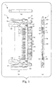
- Fig. 1 is a diagram showing a plug-type connector as an embodiment of the electrical connector according to the present invention.
- Part (a) of Fig. 1 is a right side view of the plug-type connector.
- Part (b) of Fig. 1 is a plan view of the plug-type connector.
- Part (c) of Fig. 1 is a front view of the plug-type connector.
- the plug-type connector 1 shown in Fig. 1 is used in conjunction with a receptacle-type connector 2 (see Fig. 2 ), which will be described later.
- the plug-type connector 1 is an electric part which electrically connects electric wires to a board.
- the plug-type connector 1 is mated with the receptacle-type connector 2 (see Fig. 2 ) as its counterpart connector, with its front shown in Fig. 1(c) being faced toward the receptacle-type connector 2.
- the plug-type connector 1 includes: multiple contacts 11 and 12 which carry an electrical connection between the plug-type connector 1 and the counterpart connector 2; an insulating housing 13 which holds these contacts 11 and 12; and latch members 14 which are engaged with the counterpart connector.
- the plug-type connector 1 is actually used with a metallic shielding cover 16 (see Fig. 3 ) being attached to the outer periphery of a main body section 131 of the insulating housing 13.
- Fig. 1 shows the plug-type connector 1 with the shielding cover 16 being removed from the main body part 131 for ease of view.
- the insulating housing 13 includes a main body section 131 and a plate-shaped mating section 132 protruding out in a mating direction D from an abutment surface 13a in this main body section 131, which abuts on the counterpart connector.
- the mating section 132 extends in the same width direction W as the insulating housing 13 extends.
- a pair of guide sections 133 protrude out, in the same direction as the mating section 132, from the two respective ends of the abutment surface 13a with the mating section 132 being therebetween in the width direction W.
- the insulating housing 13 is made of an insulating resin material.
- the main body section 131, the mating section 132 and the guide sections 133 are formed integrally into the insulating housing 13.
- the contacts 11 and the contacts 12 are arranged in rows in the same width direction W as the mating section 132 extends, on the two surfaces of the plate-shaped mating section 132.
- the contacts 11 and the contacts 12 are alternately arranged in a staggered manner on the two surfaces of the mating section 132.
- the contacts 11 and the contacts 12 extend from the mating section 132 to the main body section 131, and are arranged in a single row in the main body section 131.
- Multiple electric wires which are not illustrated, are connected to the contacts 11 and the contacts 12 on the main body section 131, by soldering or the like.
- the pair of latch members 14 are attached to the two sides of the insulating housing 13 in the width direction W.
- column-shaped supporting openings 13b are formed in the insulating housing 13.
- the latch members 14 are rotatably supported by the insulating member 13 and rotate about the insides of the supporting openings 13b, respectively.
- Each of the latch members 14 includes the locking section 141 which is locked into the counterpart connector. In response to a rotation of the latch member 14, the locking section 141 juts out from its guide section 133, or retracts into the guide section 133.
- each of the latch members 14 includes a spring section 142. A biasing force is applied by this spring section 142 in the same direction as the locking section 141 juts out from the guide section 133.
- Fig. 2 is an external view of the receptacle-type connector to which the plug-type connector shown in Fig. 1 is connected.
- Part (a) of Fig. 2 is a right side view of the receptacle-type connector.
- Part (b) of Fig. 2 is a front view of the receptacle-type connector.
- Part (c) of Fig. 2 is a plan view of the receptacle-type connector.
- the receptacle-type connector 2 shown in Fig. 2 includes contacts 21 and 22, and an insulating housing 23 which holds these contacts 21 and 22.
- the insulating housing 23 is provided with an elongated mating groove 231 which is open to an abutment surface 23a to abut on the plug-type connector 1.
- the contacts 21 and the contacts 22 are arranged side by side, in the same direction as the mating groove 231 extends, i.e., in the width direction W, on sidewalls 231a and 231b on the two sides of the mating groove 231.
- the contacts 21 and the contacts 22 are alternately arranged in a staggered manner on the sidewalls 231a and 231b of the mating groove 231.
- the contacts 21 and the contacts 22 are arranged in a row.
- the contacts 21 and the contacts 22 are arranged to jut from a surface on the opposite side of the abutment surface 23a of the insulating housing 23, and their jutting parts are folded.
- the contacts 21 and 22 are connected to a board (not illustrated) by soldering or the like.
- a pair of guide openings 233 are provided respectively to the two sides of the insulating housing 23 with the mating groove 231 being therebetween in the width direction W.
- Each of the guide openings 233 is continuously provided with a locking opening 233b (see Part (a) of Fig. 8 ) .
- the locking section 141 see Fig.
- Holding protrusions 232 which hold the plug-type connector 1 from both sides, are provided to protrude from the abutment surface 23a of the insulating housing 23 in the same mating direction D as the holding protrusions 232 are mated into the plug-type connector 1.
- Fig. 3 is a diagram illustrating how the plug-type connector 1 shown in Fig. 1 is connected to the receptacle-type connector 2 shown in Fig. 2 .
- Fig. 3 shows the plug-type connector 1 with the shielding cover 16 attached thereto.
- Fig. 3 shows how the mating section 132 of the plug-type connector 1 looks when seen in section.
- the plug-type connector 1 and the receptacle-type connector 2 are connected to each other with their fronts facing each other so that the abutment surface 13a of the plug-type connector 1 abuts on the abutment surface 23a of the receptacle-type connector 2.
- the mating section 132 of the plug-type connector 1 is fitted into the mating groove 231 (see Fig. 2 ) of the receptacle-type connector 2.
- the contacts 11 and the contacts 12 contact the contacts 21 and the contacts 22 (see Fig. 2 ), respectively.
- the guide sections 133 of the plug-type connector 1 are fitted into the guide openings 233 of the receptacle-type connector 2.
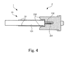
- Fig. 4 is a cross-sectional view schematically showing the plug-type connector 1 shown in Fig. 1 being connected to the receptacle-type connector 2 shown in Fig. 2 .
- each of the holding protrusions 232 of the receptacle-type connector 2 is provided in a way that the holding protrusion 232 has a space whose height is almost equal to the height of the plug-type connector 1 with the shielding cover 16 being attached thereto. For this reason, while the plug-type connector 1 and the receptacle-type connector 2 are mated with each other, the main body section 131 of the insulating housing 13 in the plug-type connector 1 is held between the two holding protrusion 232 in the receptacle-type connector 2.
- Fig. 5 is an external view showing one of the latch members 14 provided to the plug-type connector 1 shown in Fig. 1 .
- Part (a) of Fig. 5 is a front view of the latch member 14, and Part (b) of Fig. 5 is a bottom view of the latch member 14.
- the latch member 14 is a member formed by punching a corresponding piece out of a metallic plate and folding the punched-out piece.
- the latch member 14 includes: a plate-shaped rotary section 143; the hook-shaped locking section 141 provided continuously from the rotary section; and the spring section 142 continuously provided from the rotary section, in an integrated manner.
- Two arc-shaped edges 143a and 143b are formed in the periphery of the rotary section 143.
- the locking section 141 extends from between the two arc-shaped edges 143a and 143b.
- the rotary section 143 is provided with a rotary-shaft forming piece 144.
- the rotary-shaft forming piece 144 has a shape obtained by shearing a part of the rotary section 143 in an almost U shape, and by folding up the sheared part. As shown in Part (b) of Fig. 5 in detail, the rotary-shaft forming piece 144 is shaped like a hook in a manner that: a portion the rotary-shaft forming piece 144 connected to the rotary section 143 is folded up at an almost right angle to the rotary section 143; and its middle portion is additionally bent so that its front end portion is almost in parallel with the rotary section 143.
- This rotary-shaft forming piece 144 is formed by shearing its corresponding part from the rotary section 143 in the form of the U shape, and bending the sheared part.
- Fig. 6 is a magnified view showing the guide section 133 and its periphery in the insulating housing 13 shown in Fig. 1 .
- a housing compartment 135 which houses the latch member 14 is provided inside of the insulating housing 13.
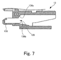
- Fig. 7 is a cross-sectional view of the insulating housing 13 shown in Fig. 6 at a location of the housing compartment 135.
- the housing compartment 135 is formed to penetrate the main body section 131 in the mating direction D and to continuously reach the inside of the guide section 133.
- the column-shaped supporting openings 13b are formed in the insulating housing 13.
- the supporting openings 13b penetrates to the housing compartment 135 from the outside of the insulating housing 13.
- An abutment section 136 consisting of two wall sections 136a and 136b is provided in a periphery of the supporting opening 13b in the housing compartment 135.
- the wall sections 136a and 136b have shapes which respectively agree with arcs of concentric circles about a point in the supporting opening 13b.
- a guide groove 137 continuous from the housing compartment 135 is formed in the insulating housing 13 as well.
- the arc-shaped edge 143b of the latch member 14 is brought into contact with the guide groove 137, and the latch member 14 is pushed and inserted into the housing compartment 135 with the locking section 141 facing the insulating housing 13.
- the height of the housing compartment 135 is less than the thickness of the latch member 14 inclusive of the rotary-shaft forming piece 144.
- the rotary-shaft forming piece 144 is pushed into the housing compartment 135 because the latch member 14 and the insulating housing 13 are elastically deformed. Once the rotary-shaft forming piece 144 reaches a location of the supporting opening 13b, the rotary-shaft forming piece 144 is received by the supporting opening 13b, and thus the latch member 14 is attached to the insulating housing 13.
- Fig. 8 is a cross-sectional view showing the latch member 14 being attached to the insulating housing 13.
- Part (a) of Fig. 8 is a diagram showing the cross-section of the insulating housing 13 at the location of the housing compartment 135 as in the case of Fig. 7 , along with the supporting opening 13b and a part of the receptacle-type connector 2.
- Part (b) of Fig. 8 is a diagram schematically showing the cross-section when viewed in a direction indicated by A in Part (a).
- the rotary-shaft forming piece 144 operates as a rotary shaft about which the latch member 14 rotates.
- a front end 144a of the U-shaped rotary-shaft forming piece 144 abuts on the inner wall of the column-shaped supporting opening 13b at an almost right angle.
- the arc-shaped edges 143a and 143b of the latch member 14 respectively abut on the two wall sections 136a and 136b constituting the abutment section 136. This prevents the rotary-shaft forming piece 144 from being detached from the supporting opening 13b, and accordingly prevents the latch member 14 from shifting toward the guide section 133, while the latch member 14 is being attached to the insulating housing 13.
- the latch member 14 is attached to the insulating housing 13, the front end of the rotary-shaft forming piece 144, and the two arc-shaped edges 143a and 143b are arranged to be distributed in almost equal intervals in a circumferential direction of concentric circles about a point in the supporting opening 13b. Furthermore, a portion of the supporting opening 13b which abuts on the rotary-shaft forming piece 144, the two wall sections 136a and 136b corresponding to the arc-shaped edges 143a and 143b are arranged to be distributed in almost equal intervals in a circumferential direction of concentric circles about the point in the supporting opening 13b.
- the guide section 133 of the plug-type connector 1 is inserted into the guide opening 233 of the receptacle-type connector 2.
- the locking section 141 is pressed by the sidewall of the guide opening 233, and the latch member 14 rotates about the point in the supporting opening 13b in a direction which causes the locking section 141 to be housed in the guide section 133.
- the latch member 14 gains in a posture indicated by the alternate long and short dash line in Part (a) of Fig. 8 .
- the latch member 14 rotates in a direction in which the locking section 141 juts out from the guide section 133 due to a biasing force of the spring section 142. As a result, the latch member 14 returns to a posture indicated by the continuous line in Part (a) of Fig. 8 .
- the latch member 14 is securely supported by the abutments at the three locations distributed in the almost equal intervals in the circumference about the rotational center in the supporting opening 13b, that is to say, the abutment between the rotary-shaft forming piece 144 and the inner surface of the supporting opening 13b, the abutment between the arc-shaped edge 143a of the latch member 14 and the wall section 136a, and the abutment between the arc-shaped edge 143b of the latch member 14 and the wall section 136b.
- the inner wall of the supporting opening 13b, the two wall sections 136a and 136b have shapes which agree with three arcs of concentric circles about the rotational center in the supporting opening 13b.
- the latch member 14 rotates smoothly while sliding the rotary-shaft forming piece 144 and the two arc-shaped edges 143a and 143b on the inner surface of the supporting opening 13b, the wall section 136a and the wall section 136b.
- the present invention is not limited to this example.
- the present invention is applicable to any other type of electrical connector, such as the receptacle-type connector.
- the embodiment has been described citing the column-shaped supporting opening 13b as an example of a member which receives the rotary-shaft forming piece 144, the present invention is not limited to this example. Any other member serves the purpose of receiving the rotary-shaft forming piece, as long as the member is a circular concave section.
- a spherical concave or the like may be provided to the housing compartment 135, and be used as the member which receives the rotary-shaft forming piece.
- the present invention is not limited to this example.
- the number of wall sections abutting on each of the arc-shaped edges may be one, or three or more.
Landscapes
- Details Of Connecting Devices For Male And Female Coupling (AREA)
- Connector Housings Or Holding Contact Members (AREA)
Applications Claiming Priority (1)
| Application Number | Priority Date | Filing Date | Title |
|---|---|---|---|
| JP2006332533A JP2008147008A (ja) | 2006-12-08 | 2006-12-08 | 電気コネクタ |
Publications (4)
| Publication Number | Publication Date |
|---|---|
| EP1930985A2 true EP1930985A2 (de) | 2008-06-11 |
| EP1930985A3 EP1930985A3 (de) | 2009-05-06 |
| EP1930985A8 EP1930985A8 (de) | 2009-07-15 |
| EP1930985A9 EP1930985A9 (de) | 2009-08-05 |
Family
ID=39131034
Family Applications (1)
| Application Number | Title | Priority Date | Filing Date |
|---|---|---|---|
| EP07122430A Withdrawn EP1930985A3 (de) | 2006-12-08 | 2007-12-05 | Elektrischer Steckverbinder |
Country Status (6)
| Country | Link |
|---|---|
| US (1) | US7628636B2 (de) |
| EP (1) | EP1930985A3 (de) |
| JP (1) | JP2008147008A (de) |
| KR (1) | KR20080053216A (de) |
| CN (1) | CN101197475B (de) |
| TW (1) | TWM336597U (de) |
Cited By (2)
| Publication number | Priority date | Publication date | Assignee | Title |
|---|---|---|---|---|
| WO2011017282A1 (en) * | 2009-08-07 | 2011-02-10 | 3M Innovative Properties Company | Floating connector |
| WO2013186585A1 (en) * | 2012-06-12 | 2013-12-19 | Fci | Connector comprising a locking device |
Families Citing this family (10)
| Publication number | Priority date | Publication date | Assignee | Title |
|---|---|---|---|---|
| CN101800378A (zh) * | 2009-11-09 | 2010-08-11 | 合兴集团汽车电子有限公司 | 具有防止匹配连接器意外脱落功能的电气连接器 |
| JP5491328B2 (ja) * | 2010-09-01 | 2014-05-14 | 株式会社東海理化電機製作所 | プラグロック構造 |
| CN202930658U (zh) | 2011-08-12 | 2013-05-08 | Fci公司 | 电连接器和电连接器组件 |
| US11637400B2 (en) | 2017-06-13 | 2023-04-25 | Samtec, Inc. | Electrical cable connector |
| USD964291S1 (en) | 2017-07-21 | 2022-09-20 | Samtec, Inc. | Electrical connector |
| TWI854328B (zh) * | 2017-07-21 | 2024-09-01 | 美商山姆科技公司 | 具有鎖扣的電連接器以及包含電連接器的系統 |
| USD896183S1 (en) | 2018-01-08 | 2020-09-15 | Samtec, Inc. | Electrical cable connector |
| CN208045748U (zh) * | 2018-01-10 | 2018-11-02 | 连展科技电子(昆山)有限公司 | 插头电连接器 |
| CN110829098B (zh) * | 2019-11-25 | 2025-10-10 | 中航光电科技股份有限公司 | 一种插座及使用该插座的头座组件 |
| US11581681B2 (en) * | 2021-04-14 | 2023-02-14 | Hewlett Packard Enterprise Development Lp | Electronic plug having a locking assembly for securing to an electronic port |
Citations (2)
| Publication number | Priority date | Publication date | Assignee | Title |
|---|---|---|---|---|
| JPH07272793A (ja) | 1994-03-10 | 1995-10-20 | Whitaker Corp:The | カードコネクタ及びそのカード排出機構 |
| JP2003297482A (ja) | 2002-02-01 | 2003-10-17 | Japan Aviation Electronics Industry Ltd | プルタブを用いたロック解除機構及びコネクタ |
Family Cites Families (8)
| Publication number | Priority date | Publication date | Assignee | Title |
|---|---|---|---|---|
| FR2664754B1 (fr) * | 1990-07-11 | 1992-10-16 | Interconnection Inf | Connecteur male pour reseau de communication informatique et/ou telephonique. |
| US5154629A (en) * | 1990-08-08 | 1992-10-13 | Icontec, Inc. | Energy transmission cable connector with latching mechanism |
| US5383794A (en) * | 1993-07-16 | 1995-01-24 | The Whitaker Corporation | Latch actuator for a connector |
| JPH0935816A (ja) * | 1995-07-19 | 1997-02-07 | Whitaker Corp:The | ラッチ付電気コネクタ |
| JP3479770B2 (ja) * | 2000-05-10 | 2003-12-15 | 日本航空電子工業株式会社 | コネクタロック構造および相手側コネクタロック構造 |
| US6726501B2 (en) * | 2002-06-21 | 2004-04-27 | Molex Incorporated | Latching system for electrical connectors |
| US6758695B2 (en) * | 2002-06-28 | 2004-07-06 | Tyco Electronics Corporation | Connector assembly with a floating shield dividing contacts formed in differential pairs |
| JP2005267970A (ja) * | 2004-03-17 | 2005-09-29 | Japan Aviation Electronics Industry Ltd | コネクタ |
-
2006
- 2006-12-08 JP JP2006332533A patent/JP2008147008A/ja not_active Withdrawn
-
2007
- 2007-10-29 TW TW096218135U patent/TWM336597U/zh not_active IP Right Cessation
- 2007-12-05 EP EP07122430A patent/EP1930985A3/de not_active Withdrawn
- 2007-12-06 US US11/951,758 patent/US7628636B2/en not_active Expired - Fee Related
- 2007-12-07 CN CN2007101989069A patent/CN101197475B/zh not_active Expired - Fee Related
- 2007-12-07 KR KR1020070126660A patent/KR20080053216A/ko not_active Withdrawn
Patent Citations (2)
| Publication number | Priority date | Publication date | Assignee | Title |
|---|---|---|---|---|
| JPH07272793A (ja) | 1994-03-10 | 1995-10-20 | Whitaker Corp:The | カードコネクタ及びそのカード排出機構 |
| JP2003297482A (ja) | 2002-02-01 | 2003-10-17 | Japan Aviation Electronics Industry Ltd | プルタブを用いたロック解除機構及びコネクタ |
Cited By (3)
| Publication number | Priority date | Publication date | Assignee | Title |
|---|---|---|---|---|
| WO2011017282A1 (en) * | 2009-08-07 | 2011-02-10 | 3M Innovative Properties Company | Floating connector |
| WO2013186585A1 (en) * | 2012-06-12 | 2013-12-19 | Fci | Connector comprising a locking device |
| US9733437B2 (en) | 2012-06-12 | 2017-08-15 | FCI Asia Pte. Ltd. | Connector comprising a locking device |
Also Published As
| Publication number | Publication date |
|---|---|
| EP1930985A8 (de) | 2009-07-15 |
| US7628636B2 (en) | 2009-12-08 |
| CN101197475A (zh) | 2008-06-11 |
| CN101197475B (zh) | 2012-08-22 |
| TWM336597U (en) | 2008-07-11 |
| JP2008147008A (ja) | 2008-06-26 |
| KR20080053216A (ko) | 2008-06-12 |
| EP1930985A9 (de) | 2009-08-05 |
| US20080139032A1 (en) | 2008-06-12 |
| EP1930985A3 (de) | 2009-05-06 |
Similar Documents
| Publication | Publication Date | Title |
|---|---|---|
| EP1930985A2 (de) | Elektrischer Steckverbinder | |
| EP2235799B1 (de) | Elektrischer steckverbinder | |
| EP1936749B1 (de) | Anschlusskontakt, Steckverbinder und Herstellungsverfahren | |
| JP3995174B2 (ja) | 電気コネクタ | |
| EP2346120B1 (de) | Abgeschirmter Verbinder und Herstellungsverfahren davon | |
| EP1856771B1 (de) | Elektrische verbinderanordnung mit einem hebel der eine vorrichtung zum niederhalten einer verriegelung hat | |
| US7785146B2 (en) | Locking device for connector elements and a connector provided with said device | |
| US6679714B2 (en) | Low insertion force type connector | |
| JP5193888B2 (ja) | コネクタ | |
| EP3067990B1 (de) | Elektrischer steckverbinder | |
| EP3764480B1 (de) | Hebelartiger anschluss | |
| CN101218714B (zh) | 带有接线端位置保证装置的连接器组件 | |
| EP1882287B1 (de) | Elektrischer verbinder mit einem verriegelungsmechanismus | |
| EP1821372B1 (de) | Steckverbinder und Methode der Montage | |
| CN104508913A (zh) | 连接器 | |
| JPH0677178U (ja) | ラッチ付き回路基板用電気コネクタ | |
| EP1973203B1 (de) | Elektrischer Verbinder mit Hebel und Hebelschutzmantel | |
| US9407047B1 (en) | Electrical connector assembly | |
| EP1739798A2 (de) | Elektrischer Verbinder mit Abschirmung | |
| EP2162958B1 (de) | Niedrigprofilkurzschlusslasche für elektrischen steckverbinder | |
| JP7500868B2 (ja) | フラットワイピング接点のための自己保持の板バネ | |
| JP2010135159A (ja) | コネクタの組立方法 | |
| EP1995828A1 (de) | Hebelsteckverbinder und Montageverfahren dafür | |
| JP5426273B2 (ja) | 端子金具 | |
| JP2012074191A (ja) | コネクタ |
Legal Events
| Date | Code | Title | Description |
|---|---|---|---|
| PUAI | Public reference made under article 153(3) epc to a published international application that has entered the european phase |
Free format text: ORIGINAL CODE: 0009012 |
|
| AK | Designated contracting states |
Kind code of ref document: A2 Designated state(s): AT BE BG CH CY CZ DE DK EE ES FI FR GB GR HU IE IS IT LI LT LU LV MC MT NL PL PT RO SE SI SK TR |
|
| AX | Request for extension of the european patent |
Extension state: AL BA HR MK RS |
|
| PUAL | Search report despatched |
Free format text: ORIGINAL CODE: 0009013 |
|
| AK | Designated contracting states |
Kind code of ref document: A3 Designated state(s): AT BE BG CH CY CZ DE DK EE ES FI FR GB GR HU IE IS IT LI LT LU LV MC MT NL PL PT RO SE SI SK TR |
|
| AX | Request for extension of the european patent |
Extension state: AL BA HR MK RS |
|
| RIC1 | Information provided on ipc code assigned before grant |
Ipc: H01R 13/627 20060101AFI20090331BHEP |
|
| RAP1 | Party data changed (applicant data changed or rights of an application transferred) |
Owner name: TYCO HOLDINGS (BERMUDA) VII LTD. Owner name: TYCO ELECTRONICS AMP K.K. |
|
| AKX | Designation fees paid | ||
| REG | Reference to a national code |
Ref country code: DE Ref legal event code: 8566 |
|
| STAA | Information on the status of an ep patent application or granted ep patent |
Free format text: STATUS: THE APPLICATION IS DEEMED TO BE WITHDRAWN |
|
| 18D | Application deemed to be withdrawn |
Effective date: 20091107 |