EP1931014A2 - Support élastique pour un générateur à haute vitesse de rotation utilisé pour applications aerospaciales - Google Patents
Support élastique pour un générateur à haute vitesse de rotation utilisé pour applications aerospaciales Download PDFInfo
- Publication number
- EP1931014A2 EP1931014A2 EP07122165A EP07122165A EP1931014A2 EP 1931014 A2 EP1931014 A2 EP 1931014A2 EP 07122165 A EP07122165 A EP 07122165A EP 07122165 A EP07122165 A EP 07122165A EP 1931014 A2 EP1931014 A2 EP 1931014A2
- Authority
- EP
- European Patent Office
- Prior art keywords
- rotor
- centering ring
- high speed
- rotating electrical
- electrical machinery
- Prior art date
- Legal status (The legal status is an assumption and is not a legal conclusion. Google has not performed a legal analysis and makes no representation as to the accuracy of the status listed.)
- Withdrawn
Links
- 239000000463 material Substances 0.000 claims description 10
- 229910052751 metal Inorganic materials 0.000 description 4
- 239000002184 metal Substances 0.000 description 4
- 238000013016 damping Methods 0.000 description 3
- 238000004519 manufacturing process Methods 0.000 description 3
- 238000000034 method Methods 0.000 description 3
- RTAQQCXQSZGOHL-UHFFFAOYSA-N Titanium Chemical compound [Ti] RTAQQCXQSZGOHL-UHFFFAOYSA-N 0.000 description 2
- 239000002131 composite material Substances 0.000 description 2
- 230000003247 decreasing effect Effects 0.000 description 2
- 229910001092 metal group alloy Inorganic materials 0.000 description 2
- 150000002739 metals Chemical class 0.000 description 2
- 238000005096 rolling process Methods 0.000 description 2
- 239000007858 starting material Substances 0.000 description 2
- 239000010936 titanium Substances 0.000 description 2
- 229910052719 titanium Inorganic materials 0.000 description 2
- 238000013459 approach Methods 0.000 description 1
- 238000009826 distribution Methods 0.000 description 1
- 238000012986 modification Methods 0.000 description 1
- 230000004048 modification Effects 0.000 description 1
- 230000000452 restraining effect Effects 0.000 description 1
- 238000003466 welding Methods 0.000 description 1
Images

Classifications
-
- H—ELECTRICITY
- H02—GENERATION; CONVERSION OR DISTRIBUTION OF ELECTRIC POWER
- H02K—DYNAMO-ELECTRIC MACHINES
- H02K5/00—Casings; Enclosures; Supports
- H02K5/04—Casings or enclosures characterised by the shape, form or construction thereof
- H02K5/16—Means for supporting bearings, e.g. insulating supports or means for fitting bearings in the bearing-shields
- H02K5/173—Means for supporting bearings, e.g. insulating supports or means for fitting bearings in the bearing-shields using bearings with rolling contact, e.g. ball bearings
- H02K5/1732—Means for supporting bearings, e.g. insulating supports or means for fitting bearings in the bearing-shields using bearings with rolling contact, e.g. ball bearings radially supporting the rotary shaft at both ends of the rotor
-
- F—MECHANICAL ENGINEERING; LIGHTING; HEATING; WEAPONS; BLASTING
- F16—ENGINEERING ELEMENTS AND UNITS; GENERAL MEASURES FOR PRODUCING AND MAINTAINING EFFECTIVE FUNCTIONING OF MACHINES OR INSTALLATIONS; THERMAL INSULATION IN GENERAL
- F16C—SHAFTS; FLEXIBLE SHAFTS; ELEMENTS OR CRANKSHAFT MECHANISMS; ROTARY BODIES OTHER THAN GEARING ELEMENTS; BEARINGS
- F16C27/00—Elastic or yielding bearings or bearing supports, for exclusively rotary movement
- F16C27/04—Ball or roller bearings, e.g. with resilient rolling bodies
-
- H—ELECTRICITY
- H02—GENERATION; CONVERSION OR DISTRIBUTION OF ELECTRIC POWER
- H02K—DYNAMO-ELECTRIC MACHINES
- H02K7/00—Arrangements for handling mechanical energy structurally associated with dynamo-electric machines, e.g. structural association with mechanical driving motors or auxiliary dynamo-electric machines
- H02K7/14—Structural association with mechanical loads, e.g. with hand-held machine tools or fans
- H02K7/16—Structural association with mechanical loads, e.g. with hand-held machine tools or fans for operation above the critical speed of vibration of the rotating parts
-
- F—MECHANICAL ENGINEERING; LIGHTING; HEATING; WEAPONS; BLASTING
- F16—ENGINEERING ELEMENTS AND UNITS; GENERAL MEASURES FOR PRODUCING AND MAINTAINING EFFECTIVE FUNCTIONING OF MACHINES OR INSTALLATIONS; THERMAL INSULATION IN GENERAL
- F16C—SHAFTS; FLEXIBLE SHAFTS; ELEMENTS OR CRANKSHAFT MECHANISMS; ROTARY BODIES OTHER THAN GEARING ELEMENTS; BEARINGS
- F16C19/00—Bearings with rolling contact, for exclusively rotary movement
- F16C19/02—Bearings with rolling contact, for exclusively rotary movement with bearing balls essentially of the same size in one or more circular rows
- F16C19/04—Bearings with rolling contact, for exclusively rotary movement with bearing balls essentially of the same size in one or more circular rows for radial load mainly
- F16C19/06—Bearings with rolling contact, for exclusively rotary movement with bearing balls essentially of the same size in one or more circular rows for radial load mainly with a single row or balls
-
- F—MECHANICAL ENGINEERING; LIGHTING; HEATING; WEAPONS; BLASTING
- F16—ENGINEERING ELEMENTS AND UNITS; GENERAL MEASURES FOR PRODUCING AND MAINTAINING EFFECTIVE FUNCTIONING OF MACHINES OR INSTALLATIONS; THERMAL INSULATION IN GENERAL
- F16C—SHAFTS; FLEXIBLE SHAFTS; ELEMENTS OR CRANKSHAFT MECHANISMS; ROTARY BODIES OTHER THAN GEARING ELEMENTS; BEARINGS
- F16C2326/00—Articles relating to transporting
- F16C2326/43—Aeroplanes; Helicopters
-
- F—MECHANICAL ENGINEERING; LIGHTING; HEATING; WEAPONS; BLASTING
- F16—ENGINEERING ELEMENTS AND UNITS; GENERAL MEASURES FOR PRODUCING AND MAINTAINING EFFECTIVE FUNCTIONING OF MACHINES OR INSTALLATIONS; THERMAL INSULATION IN GENERAL
- F16C—SHAFTS; FLEXIBLE SHAFTS; ELEMENTS OR CRANKSHAFT MECHANISMS; ROTARY BODIES OTHER THAN GEARING ELEMENTS; BEARINGS
- F16C2380/00—Electrical apparatus
- F16C2380/26—Dynamo-electric machines or combinations therewith, e.g. electro-motors and generators
Definitions
- the present invention generally relates to a mount for high speed rotating machinery and more specifically, to a resilient mount that may migrate rotor critical speeds of high speed rotating electrical machinery out of the rotor operating speed range.
- variable frequency electric generators rotate throughout a range of speeds within an operating speed range.
- the operating speed range may typically be from about 10,800 to about 24,000 revolutions per minute (rpm).
- rpm revolutions per minute
- Potentially large centrifugal forces can be imposed on the rotors of generators operating at such speeds.
- the generator rotors must be precisely balanced to avoid vibration which may lead to deviation of the rotor shaft axis from its intended axis of rotation. Practically achieving and maintaining this precision balance can be difficult due to variations in the manufacture and assembly process of generators.
- Rotor critical speed and machine response is a function of the rotor mass, the distribution of that mass, the flexibility of the shaft, the bearing support locations and the stiffness of the rotor, bearings, housing and interface between the housing and the bearings.
- Typical aerospace generators and starter generators employ rolling element bearings which have very high stiffness which may allow very little rotor variations from the rotor's intended axis of rotation. These rolling element bearings, because they have very high stiffness, places the first critical speed slightly above the maximum operating speed. As the rotor approaches the critical speed, unbalance load increases significantly resulting in large bearing loads and vibration. If an unbalanced rotor is rotating for prolonged periods of time at one of its critical speeds, it may be damaged, even catastrophically. If one of the rotor critical speeds is below the operating range, unbalance loads will be low while passing through it. Once above the first critical speed, the rotor will rotating about its mass center, resulting in low bearing loads and vibration.
- U.S. Patent No. 5,357,547 issued to Obermeyer et al. , describes vibration damping of a tubular member.
- the vibration damper uses an annular sleeve which is attachable to the inside surface of a guide thimble tube which is sized to surround the rotating instrumentation tube. Dimples are attached to the interior wall of the sleeve for radially supporting the instrumentation tube.
- the wall of the sleeve has a flexible spring member which is formed from the wall for biasing the instrumentation tube into abutment with the dimples. Flow-induced vibration of the instrumentation tube will cause it to move out of contact with the dimples and further engage the spring member, restraining further movement of the instrumentation tube.
- the Obermeyer vibration damping method may be useful for instrumentation tubes in nuclear power reactor pressure vessels, however, this method may not be particularly useful in aerospace applications, including damping vibration in high speed rotating electrical machinery.
- a high speed rotating electrical machinery comprises a rotor; a first bearing supporting the rotor; a housing supporting the first bearing; and a first centering ring positioned between the first bearing and the housing, wherein the first centering ring has a stiffness that migrates rotor critical speeds outside an operating speed range of the high speed generator.
- a centering ring comprises an annular band of material; a plurality of ID bumps equally spaced apart along an inside diameter of the annular band of material; and a plurality of OD bumps equally spaced apart along an outside diameter of the annular band of material.
- a centering ring comprises a flange on a first end of the centering ring, the flange attached to a housing of a rotating machine; a tube spring attached to the flange; and a plurality of slots cut in the tube spring.
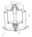
- Figure 1 is a cross-sectional view of a generator incorporating a centering ring according to one embodiment of the present invention
- Figure 2 is a perspective view of the centering ring of Figure 1 ;
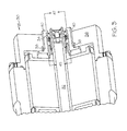
- Figure 3 is a cross-sectional view of a generator incorporating a centering ring according to another embodiment of the present invention.
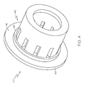
- Figure 4 is a perspective view of the centering ring of Figure 3 .
- the present invention provides a centering ring for modifying the combined resonance of a rotor and its support assembly to migrate the rotor critical speeds such that they can be engineered out of the rotor operating speed range.
- the centering rings of the present invention may be useful for any rotating electrical machinery, especially in high speed aerospace applications, such as generators and starter-generators.
- the centering rings used in the present invention may use designs, such as alternating OD bumps and ID bumps along an annular band to migrate rotor critical speeds outside of the rotor operating speed range. Furthermore, unlike conventional systems, there is no need for complex designs to effectively migrate the rotor speed out of the rotor operating speed range because the present invention uses centering rings to effectively migrate the rotor speed out of the rotor operating speed range without a complex design.
- stiffness may refer to the resiliency of an object to deformation.
- a centering ring may have a given stiffness to being deformed radially by a shaft inserted therein. Stiffness may be measured in thousands of pounds per inch (klb/in) which refers to the amount of force needed to deflect the object (centering ring, for example) one inch.
- the stiffness of the centering ring may be non-isotropic.
- FIG. 1 there is shown a cross-sectional view of a conventional generator 10 having a centering ring 20 according to an embodiment of the present invention.
- the centering ring 20 may be installed on a drive end (DE) 28 or on an opposite drive end (ODE) 29.
- Generator 10 may include a rotating shaft 12 supported by a bearing 14.
- the centering ring 20 may be disposed between the bearing 14, having an outside diameter 27, and a housing 16.
- the centering ring 20 may include a band 22 of material with a number of equally spaced support bumps along an outside diameter (OD) of the band 22, also referred to as OD bumps 24. In between the OD bumps 24 may be disposed an equal number of bumps along an inside diameter (ID) of the band 22, also referred to as ID bumps 26.
- ID bumps 26 By placing the centering ring 20 into position around the outside diameter of the bearing 14, the OD bumps 24 and ID bumps 26 may act as lands which may contact the outside diameter 27 of the bearing 14 and the inside diameter of the housing 16 (see Figure 1 ).
- the band 22 of material between the OD bumps 24 and ID bumps 26 may deflect due to the vibration of the shaft 12 within the bearing 14.
- the presence of the centering ring 20 between the bearing 14 and the housing 16 may provide a resilient stiffness to migrate the critical speed of the shaft 12 outside of the operating speed range of the generator 10.
- the band 22 may have an inside diameter 25 essentially the same as the outside diameter 27 of the bearing 14 (see Figure 1 ). In other words, the band 22 should fit around the bearing 14 with the ID bumps 26 of the bearing 14 engaging the outside diameter 27 of the bearing 14.
- the band 22 may be made of any material such as metal, composite and the like. Suitable metals may include titanium or a metal alloy such as InconelTM.
- the band 22 may have a thickness T adequate to provide resilience to vibration in order to migrate the critical speeds of the shaft 12 (see Figure 1 ) outside of the shaft operating speed range.
- the number of bumps 24, 26 and a spacing 23 therebetween may be determined based on the critical speeds of the system and the stiffness needed to migrate the rotor critical speeds outside of the rotor operating speed range.
- the stiffness of the centering ring 20 may increase, thereby absorbing less vibrations of the shaft 12.
- the centering ring 20 may be designed to have an overall stiffness between about 5 klb/in and about 1000 klb/in.
- the stiffness of the centering spring will depend on the stiffness required to maintain critical speeds below and above the operating speed range. Too low of stiffness might place a critical speed significantly below the minimum operating speed, however, this could results in a critical speed close to the maximum operating speed. In some cases, centering springs of different stiffness might need to be incorporated at each bearing to maintain critical speed margin with respect to the minimum operating speed and the maximum operating speed.
- Generator 30 may include a rotating shaft 32 supported by a bearing 34.
- the centering ring 40 may be attached, for example, by bolts 38 to a housing 36.
- the centering ring 40 may have an inside diameter 45 that may fit about an outside diameter 47 of the bearing 34.
- the centering ring 40 may be a tube spring 46 having a flange 42 formed on a first end 44.
- the tube spring 46 may be attached to the flange 42 by conventional means, such as welding, or may be formed integrally with the flange 42 during manufacture.
- the flange 42 may be attached, by bolts (not shown) for example, to the housing 36.
- the tube spring 46 of the centering ring 40 may be installed about the bearing 34.
- the bearing 34 may be cantilevered from the housing 36 in the centering ring 40. Under bearing load, the centering ring 40 may deflect due to the vibration of the shaft 32 within the bearing 34.
- the presence of the centering ring 40 between the bearing 34 and the housing 36 may provide a resilient stiffness to migrate the critical speed of the shaft 32 outside of the operating speed range of the generator 30.
- the centering ring may include a plurality of slots 48 cut along an axial direction of the centering ring 40 as shown in Figure 4 .
- the number and size of the slots 48 may be determined based on the critical speeds of the system and the stiffness needed to migrate the rotor critical speeds outside of the rotor operating speed range. For example, by decreasing the number of slots 48, the stiffness of the centering ring 40 may increase, thereby absorbing less vibrations of the shaft 32.
- the centering ring 40 may be designed to have an overall stiffness between about 5 klb/in and about 1000 klb/in.
- a centering ring 40 having a greater relative stiffness may migrate the rotor critical speeds to a lesser extent as compared to a centering ring 40 having a lower relative stiffness.
- the centering ring 40 may be mounted on either the drive end (DE) or on the opposite drive end (ODE) of the generator 30 shown in Figure 3 .
- the centering ring 40 may have an inside diameter 45 essentially the same as the outside diameter 47 of the bearing 34.
- the centering ring 40 may be made of any material such as metal, composite and the like. Suitable metals may include titanium or a metal alloy such as InconelTM.
- Either of the centering rings 20, 40 may be used to modify the combined resonance of the rotor 12, 32 and support assembly (housing 16, 36). This may be achieved in any number of ways.
- the first rotor critical speed may be migrated such that the operating speed range of the rotor falls below this first critical speed.
- the rotor critical speeds may be migrated such that the first rotor critical speed is below the operating speed range of the rotor and a second rotor critical speed is above the operating speed range of the rotor.
- rotor critical speeds may be migrated by adjusting the resilience of the centering ring 20, 40 according to the present invention.
Landscapes
- Engineering & Computer Science (AREA)
- Power Engineering (AREA)
- General Engineering & Computer Science (AREA)
- Mechanical Engineering (AREA)
- Motor Or Generator Frames (AREA)
- Connection Of Motors, Electrical Generators, Mechanical Devices, And The Like (AREA)
- Support Of The Bearing (AREA)
Applications Claiming Priority (1)
| Application Number | Priority Date | Filing Date | Title |
|---|---|---|---|
| US11/566,881 US7589447B2 (en) | 2006-12-05 | 2006-12-05 | High speed aerospace generator resilient mount |
Publications (1)
| Publication Number | Publication Date |
|---|---|
| EP1931014A2 true EP1931014A2 (fr) | 2008-06-11 |
Family
ID=38961331
Family Applications (1)
| Application Number | Title | Priority Date | Filing Date |
|---|---|---|---|
| EP07122165A Withdrawn EP1931014A2 (fr) | 2006-12-05 | 2007-12-03 | Support élastique pour un générateur à haute vitesse de rotation utilisé pour applications aerospaciales |
Country Status (2)
| Country | Link |
|---|---|
| US (1) | US7589447B2 (fr) |
| EP (1) | EP1931014A2 (fr) |
Families Citing this family (6)
| Publication number | Priority date | Publication date | Assignee | Title |
|---|---|---|---|---|
| US8337090B2 (en) * | 2009-09-10 | 2012-12-25 | Pratt & Whitney Canada Corp. | Bearing support flexible ring |
| US9057415B1 (en) | 2011-06-17 | 2015-06-16 | The United States Of America As Represented By The Secretary Of The Navy | Adaptable multi-element vibration isolator |
| EP2899854B8 (fr) * | 2014-01-23 | 2016-09-21 | General Electric Technology GmbH | Segment de doigt d'amortisseur |
| US9845860B2 (en) * | 2015-07-20 | 2017-12-19 | Dayco Ip Holdings, Llc | Retaining clamp for molded plastics |
| CN109256884A (zh) * | 2017-10-13 | 2019-01-22 | 朱卫 | 一种用钛金属生产的马达外壳 |
| CN115614384B (zh) * | 2022-10-13 | 2024-07-19 | 中国航发四川燃气涡轮研究院 | 一种鼠笼加弹性环组合式弹性支承的刚度分配方法 |
Citations (1)
| Publication number | Priority date | Publication date | Assignee | Title |
|---|---|---|---|---|
| US5357547A (en) | 1992-03-18 | 1994-10-18 | Westinghouse Electric Corporation | Vibration dampener for dampening vibration of a tubular member |
Family Cites Families (20)
| Publication number | Priority date | Publication date | Assignee | Title |
|---|---|---|---|---|
| US1386255A (en) * | 1919-04-29 | 1921-08-02 | John George William Gruban | Roller, ball, and other bearing |
| US3097895A (en) * | 1960-11-10 | 1963-07-16 | Thompson Ramo Wooldridge Inc | Bearing suspension |
| US3503121A (en) * | 1967-11-09 | 1970-03-31 | Textron Inc | Self-locking bearing ring |
| US3557421A (en) * | 1968-06-20 | 1971-01-26 | Textron Inc | Method for making a self-locking ring |
| US3679279A (en) * | 1970-03-26 | 1972-07-25 | Textron Inc | Self-locking ring construction |
| US4682065A (en) * | 1985-11-13 | 1987-07-21 | Nidec-Torin Corporation | Molded plastic motor housing with integral stator mounting and shaft journalling projection |
| US5044789A (en) * | 1990-04-16 | 1991-09-03 | Eaton Corporation | Roller and ball bearing bearing isolator |
| JPH05161299A (ja) * | 1991-12-03 | 1993-06-25 | Mabuchi Motor Co Ltd | 小型モータの軸受装置 |
| US5564903A (en) * | 1993-11-23 | 1996-10-15 | Alliedsignal Inc. | In-line ram air turbine power system |
| US5527115A (en) * | 1994-07-11 | 1996-06-18 | The Hoover Company | Bearing mounting arrangement |
| US5505587A (en) | 1995-01-05 | 1996-04-09 | Northrop Grumman Corporation | RAM air turbine generating apparatus |
| US5848461A (en) * | 1996-05-28 | 1998-12-15 | Ford Motor Company | Electrical machine having a rotor with an improved rotor stop |
| US5899443A (en) | 1996-10-22 | 1999-05-04 | The United States Of America As Represented By The Secretary Of The Navy | Passive-active vibration isolation |
| DE19648854C2 (de) * | 1996-11-26 | 2003-10-02 | Ina Schaeffler Kg | Pendelkugellager |
| CA2441622C (fr) * | 2001-03-16 | 2010-06-08 | Altech Generating Systems Llc | Alternateur et procede de fabrication dudit alternateur |
| US6695294B2 (en) | 2001-07-20 | 2004-02-24 | Lord Corporation | Controlled equilibrium device with displacement dependent spring rates and integral damping |
| US6746005B1 (en) | 2001-10-04 | 2004-06-08 | The United States Of America As Represented By The Secretary Of The Navy | Constant natural frequency passive-active mount |
| KR20040094742A (ko) * | 2002-02-28 | 2004-11-10 | 룩라멜렌운트쿠플룽스바우베타일리궁스카게 | 베이스에 샤프트를 장착하기 위한 디커플링 장치 및레이디얼 웨이브 와셔 |
| US6939052B1 (en) * | 2003-01-27 | 2005-09-06 | Precision Components, Inc. | Bearing with integrated mounting features |
| JP3983690B2 (ja) * | 2003-02-18 | 2007-09-26 | 三菱電機株式会社 | 回転電機 |
-
2006
- 2006-12-05 US US11/566,881 patent/US7589447B2/en active Active
-
2007
- 2007-12-03 EP EP07122165A patent/EP1931014A2/fr not_active Withdrawn
Patent Citations (1)
| Publication number | Priority date | Publication date | Assignee | Title |
|---|---|---|---|---|
| US5357547A (en) | 1992-03-18 | 1994-10-18 | Westinghouse Electric Corporation | Vibration dampener for dampening vibration of a tubular member |
Also Published As
| Publication number | Publication date |
|---|---|
| US20080129134A1 (en) | 2008-06-05 |
| US7589447B2 (en) | 2009-09-15 |
Similar Documents
| Publication | Publication Date | Title |
|---|---|---|
| EP1895178A2 (fr) | Montage souple à rigidité uniforme | |
| EP1965093B1 (fr) | Appareil pour l'amortissement du rotor | |
| EP1490583B1 (fr) | Amortisseur a support anisotrope pour palier de turbine a gaz | |
| US7857519B2 (en) | Compact bearing support | |
| US10107378B2 (en) | Systems and methods for a gas turbine engine with combined multi-directional gearbox deflection limiters and dampers | |
| JP5187593B2 (ja) | 真空ポンプ | |
| EP1891332B2 (fr) | Pompe a vide | |
| EP1931014A2 (fr) | Support élastique pour un générateur à haute vitesse de rotation utilisé pour applications aerospaciales | |
| JP5585082B2 (ja) | 真空ポンプ | |
| US4046430A (en) | Damped intershaft bearing and stabilizer | |
| EP1942291A1 (fr) | Montage résilient de générateur aérospatial haute vitesse, ressort central combiné et amortisseur de film compressé | |
| US6817266B1 (en) | Stiff metal hub for an energy storage rotor | |
| JP2002535571A (ja) | 柔軟なベアリング支持体 | |
| AU2022235620B2 (en) | Damper bearing and damper | |
| USRE30210E (en) | Damped intershaft bearing and stabilizer | |
| JP7523087B2 (ja) | 軸受構造 | |
| JP2009174692A (ja) | 軸受装置及び遠心圧縮機 | |
| JP6767720B2 (ja) | ターボ機械 | |
| EP4308823B1 (fr) | Amortisseur de palier de rotor pour pompe à vide | |
| JPH07167216A (ja) | 回転体の振動緩和装置 | |
| WO2026024271A1 (fr) | Système de réduction de vibrations dans un rotor | |
| EP2386779B1 (fr) | Rotors pour machines électriques | |
| WO2026024272A1 (fr) | Système et procédé de commande de vibrations dans un rotor | |
| JPS5951108A (ja) | 蒸気タ−ビン |
Legal Events
| Date | Code | Title | Description |
|---|---|---|---|
| PUAI | Public reference made under article 153(3) epc to a published international application that has entered the european phase |
Free format text: ORIGINAL CODE: 0009012 |
|
| 17P | Request for examination filed |
Effective date: 20071203 |
|
| AK | Designated contracting states |
Kind code of ref document: A2 Designated state(s): AT BE BG CH CY CZ DE DK EE ES FI FR GB GR HU IE IS IT LI LT LU LV MC MT NL PL PT RO SE SI SK TR |
|
| AX | Request for extension of the european patent |
Extension state: AL BA HR MK RS |
|
| STAA | Information on the status of an ep patent application or granted ep patent |
Free format text: STATUS: THE APPLICATION HAS BEEN WITHDRAWN |
|
| 18W | Application withdrawn |
Effective date: 20100429 |