EP1931085B1 - Modulare Netzwerkverbindungsvorrichtung - Google Patents
Modulare Netzwerkverbindungsvorrichtung Download PDFInfo
- Publication number
- EP1931085B1 EP1931085B1 EP06125497A EP06125497A EP1931085B1 EP 1931085 B1 EP1931085 B1 EP 1931085B1 EP 06125497 A EP06125497 A EP 06125497A EP 06125497 A EP06125497 A EP 06125497A EP 1931085 B1 EP1931085 B1 EP 1931085B1
- Authority
- EP
- European Patent Office
- Prior art keywords
- module
- chassis
- uplink
- network
- connection
- Prior art date
- Legal status (The legal status is an assumption and is not a legal conclusion. Google has not performed a legal analysis and makes no representation as to the accuracy of the status listed.)
- Not-in-force
Links
- 238000009434 installation Methods 0.000 claims description 10
- 238000000034 method Methods 0.000 claims description 10
- 229920006235 chlorinated polyethylene elastomer Polymers 0.000 description 10
- 239000000835 fiber Substances 0.000 description 10
- 230000003287 optical effect Effects 0.000 description 3
- 101150012579 ADSL gene Proteins 0.000 description 1
- 102100020775 Adenylosuccinate lyase Human genes 0.000 description 1
- 108700040193 Adenylosuccinate lyases Proteins 0.000 description 1
- 241000282326 Felis catus Species 0.000 description 1
- 238000000136 cloud-point extraction Methods 0.000 description 1
- 230000008878 coupling Effects 0.000 description 1
- 238000010168 coupling process Methods 0.000 description 1
- 238000005859 coupling reaction Methods 0.000 description 1
- 238000011161 development Methods 0.000 description 1
- 230000018109 developmental process Effects 0.000 description 1
- 239000013307 optical fiber Substances 0.000 description 1
- 230000000750 progressive effect Effects 0.000 description 1
- 230000001681 protective effect Effects 0.000 description 1
Images


Classifications
-
- H—ELECTRICITY
- H04—ELECTRIC COMMUNICATION TECHNIQUE
- H04L—TRANSMISSION OF DIGITAL INFORMATION, e.g. TELEGRAPHIC COMMUNICATION
- H04L12/00—Data switching networks
- H04L12/28—Data switching networks characterised by path configuration, e.g. LAN [Local Area Networks] or WAN [Wide Area Networks]
- H04L12/2803—Home automation networks
- H04L12/2805—Home Audio Video Interoperability [HAVI] networks
-
- H—ELECTRICITY
- H05—ELECTRIC TECHNIQUES NOT OTHERWISE PROVIDED FOR
- H05K—PRINTED CIRCUITS; CASINGS OR CONSTRUCTIONAL DETAILS OF ELECTRIC APPARATUS; MANUFACTURE OF ASSEMBLAGES OF ELECTRICAL COMPONENTS
- H05K5/00—Casings, cabinets or drawers for electric apparatus
- H05K5/30—Side-by-side or stacked arrangements
-
- Y—GENERAL TAGGING OF NEW TECHNOLOGICAL DEVELOPMENTS; GENERAL TAGGING OF CROSS-SECTIONAL TECHNOLOGIES SPANNING OVER SEVERAL SECTIONS OF THE IPC; TECHNICAL SUBJECTS COVERED BY FORMER USPC CROSS-REFERENCE ART COLLECTIONS [XRACs] AND DIGESTS
- Y10—TECHNICAL SUBJECTS COVERED BY FORMER USPC
- Y10T—TECHNICAL SUBJECTS COVERED BY FORMER US CLASSIFICATION
- Y10T29/00—Metal working
- Y10T29/49—Method of mechanical manufacture
- Y10T29/49002—Electrical device making
- Y10T29/49117—Conductor or circuit manufacturing
Definitions
- This invention relates to a modular apparatus for installation in a customer's premises and for connection to a network.
- the invention is particularly applicable to use with broadband networks such as triple-play networks.
- a single network connection is used to provide voice (telephony), internet and TV connectivity.
- a single cable often an optical cable is run to a customer's premises, e.g. a house, apartment, etc., and the customer then attaches suitable equipment (telephones, TV sets, computers, etc.) to this single connection.
- suitable equipment telephones, TV sets, computers, etc.
- a cable is run to the customer's premises and connected to equipment that provides the functional connection for the various devices.
- This equipment is often known generically as 'customer premise equipment' or 'CPE'. More specifically, as the equipment involves a switch function, it can be know as 'customer premise switch' or CPS.
- the cable connection to the customer premises is just that, a simple cable run into the premises.
- termination units are often provided to secure the customer end of the cable.
- these units are know as 'fibre termination units' or 'FTUs'.
- termination units are merely mechanical devices that secure the end of the fibre to a surface such as a wall, and provide a connector into which the fibre is connected and onto which the customer can connect appropriate equipment.
- More sophisticated FTUs can include functional elements such as a cable TV module to convert TV signals on the fibre into a normal antenna signal that can be connected to a TV.
- CPS 300 of PacketFront Sweden One example of a CPS used with an FTU is the CPS 300 of PacketFront Sweden.
- Each device is served by a multi-media processing modules, which receives a multi-media signal from a network interface module and routes at least one multi-media signal to a corresponding multi-media device; and US6059614 which discloses a modular home information center includes a number of processing modules having substantially identical housings with each of the modules having an operating structure and a multi-bus connector within the housing of the module.
- This invention seeks to provide an apparatus that allows progressive increase in functionality without the need to incur large up-front costs.
- This invention provides apparatus for connecting to a broadband network as described in claim 1.
- the uplink module preferably includes a cable terminator, a converter for providing a signal input and output from and to the cable and converting between received cable signals and electrical network signals, and a power source.
- the switch module which can be connected to the uplink module so as to be able to send and receive electrical network signals and receive power, and providing one or more ports for connection of network devices, a port for connection of the voice over IP module and a port for connection of the wireless network module.
- the voice over IP and/or wireless network module can be connected to the switch module so as to be able to exchange network signals therewith and connected to the uplink module so as to receive power therefrom.
- Dummy modules can be provided for use when not all of the functional modules are installed on the chassis.
- the invention also provides a method of providing a broadband network connection to a location as described in claim 6.
- the method can also comprise the further steps of: installing on the chassis a switch module providing one or more ports for connection of network devices, a port for connection of a voice over IP module and a port for connection of a wireless network module and connecting the switch module to the uplink module so as to be able to send and receive electrical network signals and receive power; installing on the chassis a voice over IP module and connecting the voice over IP module to the switch module so as to be able to exchange network signals therewith and connected to the uplink module so as to receive power therefrom; and installing on the chassis a wireless network module and connecting the wireless network module to the switch module so as to be able to exchange network signals therewith and connected to the uplink module so as to receive power therefrom.
- one or more dummy modules can be installed.
- the dummy modules can then be removed at a later time when the relevant functional module is installed.
- the cover can be replaced after installing the module(s).
- the invention also offers a new business model, comprising:
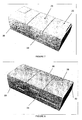
- the apparatus shown in Figure 1 comprises a CPE suitable for residential uses. It broadly comprises a base unit 10 comprising a chassis 12 that can be fixed to a wall (not shown), and a cover 14 that can be fixed to the chassis 12 to define a housing. The cover 14 can be removed to allow functional parts of the CPE to be installed as are discussed in more detail below.
- the chassis comprises a fibre termination unit (FTU) 16 which provides a mechanical connection to which a network cable can be connected and which provides termination and a connection including a cover 18 to which other modules can be connected as shown in Figure 2 . While optical fibre is seen as the most common use for this apparatus, other network cable can also be accommodated.
- the chassis also comprises a number of mounting points into which other modules can be fitted.
- the base unit 10 comprises no electronic or electrical function but merely provides a mechanical location of the network cable entering the premises and protective covers 14, 18.
- the base unit 10 can be made at relatively low cost and can be installed in all premises served by the network, whether or not any network service are provided.
- the chassis 12 and the covers 14, 18 provide physical protection for the end of the cable and a convenient location into which functional modules can be connected.
- the first functional module that must be connected to provide network functions is an uplink module 20 (sometimes called a 'managed media converter').
- the uplink module 20 provides functional termination of the fibre and a converter to convert the optical signals on the fibre to electrical network signals such as Ethernet signals which can be provided on a standard Ethernet output connection 21.
- the uplink converter 20 is also provided with a power supply with a connector for connection to an electrical supply and, optionally, an RF overlay option that converts cable TV signals provided on the fibre to conventional TV antenna signals that can be provided by a conventional TV antenna output 22, and a standard telephone socket to which conventional telephone equipment can be connected.
- the uplink module 20 can also be provided with a power switch and LED indicators showing function and status of the device.
- the uplink module 20 is installed on the FTU 16 by removing the cover 14 and sliding the module 20 (arrow A of Figure 3 ) into the fittings to connect to the FTU at the side of the cover 18.
- the uplink module also provides connections to provide power and network connections for other functional modules to be housed in the base unit 10.
- a basic Ethernet card 23 can be connected to the uplink module 20 by sliding (arrow B of Figure 4 ) to connect to the connector 21.
- Dummy modules 25 are provided on top of the Ethernet card 23 to complete the installation ( Figure 5 ).
- the next module to be connected is a switch module 24.
- the switch module 24 is installed in a similar way to the Ethernet card 23 and connects to the power supply and Ethernet output 21 of the uplink module 20 and provided a number of Ethernet connection ports, typically eight ports. Typically two of these ports will be dedicated to specific functional modules as is described below. The remainder of the ports are provided with conventions connection sockets to allow Ethernet devices to be attached in the normal manner.
- Dummy modules 25 can be provided as described above (see Figure 6 ).
- a voice over IP (VOIP) module 26 can be connected.
- the VOIP module 26 connects to the assigned Ethernet port on the switch module 24 and to the power supply of the uplink module 20 and is provided with a suitable connection for telephony devices.
- the VOIP module 26 converts the VOIP signals on the network to and from PSTN signals allowing conventional telephony devices to be used.
- the other dedicated Ethernet port is arranged so that a wireless network module 28 can be installed.
- the wireless network module 28 similarly connects to the assigned Ethernet port of the switch module 24 and to the power supply of the uplink module 20 in a similar manner to the VOIP module 26 described above and is shown in Figure 8 .
- An antenna 30 is provided on the wireless module 28.
- the wireless network module converts the conventional Ethernet signals to and from wireless Ethernet signals to one or more wireless devices.
- the wireless module 28 can also be installed without the VOIP module 26, in which case a dummy module could be installed.
- the uplink module 20 can be used to terminate passive optical network (PON), active Ethernet FTTH (fibre to the home), or TP (cat 5)-based Ethernet.
- PON passive optical network
- FTTH active Ethernet FTTH
- TP cat 5-based Ethernet
- the modular nature of the apparatus according to the invention means that the various functional modules can be added or removed as the service provision to the residence changes. By simply removing the cover and/or dummy modules, each module can be attached, using the power and network connections provided. This also allows the network provider to avoid the cost of supplying all of the functional network modules ab initio. Thus the cost of providing the necessary hardware can be borne by the user and/or the service provider, lowering the up-front cost of providing network connection to premises.
- the network owner might provide the base unit and uplink module as the basic network infrastructure, the subscriber might purchase the switch module so as to be able to extend use of the network connection to other devices (much as in the way that users buy routers for connection to ADSL services today) and the service provider(s) provide the VOIP and wireless modules as part of a service package.
- the modular device With providing the modular device with the common connections, it is possible to treat the CPE as a single device both physically and logically in network administration.
Landscapes
- Engineering & Computer Science (AREA)
- Microelectronics & Electronic Packaging (AREA)
- Multimedia (AREA)
- Automation & Control Theory (AREA)
- Computer Networks & Wireless Communication (AREA)
- Signal Processing (AREA)
- Mobile Radio Communication Systems (AREA)
- Telephonic Communication Services (AREA)
- Small-Scale Networks (AREA)
- Details Of Indoor Wiring (AREA)
Claims (13)
- Gerät zum Anschließen eines Breitbandnetzwerkes, umfassend:- ein Chassis (12), das Montagepunkte für ein Aufwärtsstreckenmodul und für Schalt-, VoIP- und drahtlose Netzwerkmodule (23, 24, 26) umfasst, die auch funktionsmäßig an das Aufwärtsstreckenmodul für Energie und Netzwerkanschluss angeschlossen sind;- eine Kabelabschlusseinheit (16), die an dem Chassis montiert ist; und- einen Deckel (14), der an dem Chassis montiert ist und einfach abzunehmen ist, um einen mühelosen Zugriff auf das Chassis zu ermöglichen,dadurch gekennzeichnet, dass das Chassis (12) dazu konfiguriert ist, eine Ebene zu definieren, und das Aufwärtsstreckenmodul (20) an dem Gerät in einer Richtung, die zu der Ebene im Wesentlichen parallel ist, gleitbar angeschlossen ist.
- Gerät nach Anspruch 1, umfassend ein Aufwärtsstreckenmodul, das einen Kabelabschluss, einen Wandler zum Bereitstellen einer Signaleingabe in und Signalausgabe aus dem Kabel und zum Umwandeln zwischen empfangenen Kabelsignalen und elektrischen Netzwerksignalen und eine Energiequelle umfasst.
- Gerät nach Anspruch 2, umfassend ein Schaltmodul, das an das Aufwärtsstreckenmodul angeschlossen ist, um elektrische Netzwerksignale senden und empfangen, und Energie empfangen zu können, und das eine oder mehrere Schnittstellen zum Anschluss von Netzwerkvorrichtungen, eine Schnittstelle zum Anschluss des VoIP-Moduls und eine Schnittstelle zum Anschluss des drahtlosen Netzwerkmoduls bereitstellt.
- Gerät nach Anspruch 3, ferner umfassend ein VoIP-Modul, das an das Schaltmodul angeschlossen ist, um damit Netzwerksignale austauschen zu können, und das an das Aufwärtsstreckenmodul angeschlossen ist, um davon Energie zu empfangen.
- Gerät nach Anspruch 3 oder 4, ferner umfassend ein drahtloses Netzwerkmodul, das an das Schaltmodul angeschlossen ist, um damit Netzwerksignale austauschen zu können, und das an das Aufwärtsstreckenmodul angeschlossen ist, um davon Energie zu empfangen.
- Verfahren zum Bereitstellen eines Breitbandnetzwerkanschlusses für einen Standort, umfassend folgende Schritte:i) Installieren einer Basiseinheit an dem Standort, wobei die Basiseinheit Folgendes umfasst:- ein Chassis (12), das Montagepunkte für ein Aufwärtsstreckenmodul und für Schalt-, VoIP- und drahtlose Netzwerkmodule (23, 24, 26) umfasst, die auch funktionsmäßig an das Aufwärtsstreckenmodul für Energie und Netzwerkanschluss angeschlossen sind;- eine Kabelabschlusseinheit (16), die an dem Chassis montiert ist; und- einen Deckel (14), der an dem Chassis montiert ist und einfach abzunehmen ist, um einen mühelosen Zugriff auf das Chassis zu ermöglichen,ii) Anschließen eines Breitbandnetzwerkkabels an die Basiseinheit;iii) anschließend Abnehmen des Deckels und Installieren eines Aufwärtsstreckenmoduls auf dem Chassis, wobei das Aufwärtsstreckenmodul einen Kabelabschluss, einen Wandler zum Bereitstellen von Signaleingabe in und Signalausgabe von dem Kabel und zum Umwandeln zwischen empfangenen Kabelsignalen und elektrischen Netzwerksignalen und eine Energiequelle umfasst; undiv) Anschließen des Kabels an das Aufwärtsstreckenmodul,dadurch gekennzeichnet, dass das Chassis (12) eine Ebene definiert, und das Aufwärtsstreckenmodul (20) an das Gerät in einer Richtung, die zu der Ebene im Wesentlichen parallel ist, gleitbar angeschlossen ist.
- Verfahren nach Anspruch 6, ferner umfassend folgende Schritte:v) Installieren auf dem Chassis eines Schaltmoduls, das eine oder mehrere Schnittstellen zum Anschluss von Netzwerkvorrichtungen, eine Schnittstelle zum Anschluss eines VoIP-Moduls und eine Schnittstelle zum Anschluss eines drahtlosen Netzwerkmoduls bereitstellt, und Anschließen des Schaltmoduls an das Aufwärtsstreckenmodul, um elektrische Netzwerksignale senden und empfangen und Energie empfangen zu können.
- Verfahren nach Anspruch 7, ferner umfassend folgende Schritte:vi) Installieren auf dem Chassis eines VoIP-Moduls und Anschließen des VoIP-Moduls an das Schaltmodul, um damit Netzwerksignale austauschen zu können, und das an das Aufwärtsstreckenmodul angeschlossen ist, um davon Energie empfangen zu können.
- Verfahren nach Anspruch 7 oder 8, ferner umfassend folgende Schritte:vii) Installieren auf dem Chassis eines drahtlosen Netzwerkmoduls und Anschließen des drahtlosen Netzwerkmoduls an das Schaltmodul, um damit Netzwerksignale austauschen zu können, und das an das Aufwärtsstreckenmodul angeschlossen ist, um davon Energie zu empfangen.
- Verfahren nach Anspruch 6, ferner umfassend nach der Installation des Aufwärtsstreckenmoduls, das Installieren auf dem Chassis von:- einem Schaltmodul, das eine oder mehrere Schnittstellen zum Anschluss von Netzwerkvorrichtungen, eine Schnittstelle zum Anschluss eines VoIP-Moduls und eine Schnittstelle zum Anschluss eines drahtlosen Netzwerkmoduls bereitstellt, und Anschließen des Schaltmoduls an das Aufwärtsstreckenmodul, um elektrische Netzwerksignale senden und empfangen und Energie empfangen zu können; und- einem oder mehreren abnehmbaren Blindmodulen, die später abgenommen werden können, um weitere funktionsfähige Module zu installieren.
- Verfahren nach Anspruch 10, ferner umfassend folgende Schritte nach der Installation des Schaltmoduls:a) Abnehmen eines Blindmoduls; undb) Installieren an seiner Stelle eines VoIP-Moduls und Anschließen des VoIP-Moduls an das Schaltmodul, um damit Netzwerksignale austauschen zu können, und das an das Aufwärtsstreckenmodul angeschlossen ist, um davon Energie zu empfangen.
- Verfahren nach Anspruch 10 oder 11, ferner umfassend folgende Schritte nach der Installation des Schaltmoduls:a) Abnehmen eines Blindmoduls; undb) Installieren an seiner Stelle eines drahtlosen Netzwerkmoduls und Anschließen des drahtlosen Netzwerkmoduls an das Schaltmodul, um damit Netzwerksignale austauschen zu können, und das an das Aufwärtsstreckenmodul angeschlossen ist, um davon Energie zu empfangen.
- Verfahren nach einem der Ansprüche 6 bis 12, ferner umfassend das Wiederanbringens des Deckels nach der Installation eines oder mehrerer Module.
Priority Applications (5)
| Application Number | Priority Date | Filing Date | Title |
|---|---|---|---|
| EP06125497A EP1931085B1 (de) | 2006-12-06 | 2006-12-06 | Modulare Netzwerkverbindungsvorrichtung |
| CN200780045045A CN101632258A (zh) | 2006-12-06 | 2007-12-06 | 模块式网络连接设备 |
| PCT/EP2007/063467 WO2008068316A1 (en) | 2006-12-06 | 2007-12-06 | Modular network connection equipment |
| US12/517,728 US8326108B2 (en) | 2006-12-06 | 2007-12-06 | Modular network connection equipment |
| EP07847937A EP2095573B1 (de) | 2006-12-06 | 2007-12-06 | Modulare netzwerkverbindungsgeräte |
Applications Claiming Priority (1)
| Application Number | Priority Date | Filing Date | Title |
|---|---|---|---|
| EP06125497A EP1931085B1 (de) | 2006-12-06 | 2006-12-06 | Modulare Netzwerkverbindungsvorrichtung |
Publications (2)
| Publication Number | Publication Date |
|---|---|
| EP1931085A1 EP1931085A1 (de) | 2008-06-11 |
| EP1931085B1 true EP1931085B1 (de) | 2012-07-18 |
Family
ID=37945924
Family Applications (2)
| Application Number | Title | Priority Date | Filing Date |
|---|---|---|---|
| EP06125497A Not-in-force EP1931085B1 (de) | 2006-12-06 | 2006-12-06 | Modulare Netzwerkverbindungsvorrichtung |
| EP07847937A Not-in-force EP2095573B1 (de) | 2006-12-06 | 2007-12-06 | Modulare netzwerkverbindungsgeräte |
Family Applications After (1)
| Application Number | Title | Priority Date | Filing Date |
|---|---|---|---|
| EP07847937A Not-in-force EP2095573B1 (de) | 2006-12-06 | 2007-12-06 | Modulare netzwerkverbindungsgeräte |
Country Status (4)
| Country | Link |
|---|---|
| US (1) | US8326108B2 (de) |
| EP (2) | EP1931085B1 (de) |
| CN (1) | CN101632258A (de) |
| WO (1) | WO2008068316A1 (de) |
Families Citing this family (8)
| Publication number | Priority date | Publication date | Assignee | Title |
|---|---|---|---|---|
| EP1931085B1 (de) | 2006-12-06 | 2012-07-18 | Genexis B.V. | Modulare Netzwerkverbindungsvorrichtung |
| EP1973269B1 (de) | 2007-03-22 | 2013-04-24 | PacketFront Software Solutions AB | Konfigurationsvorprozessorsprache |
| EP2048848B1 (de) | 2007-10-12 | 2013-12-18 | PacketFront Network Products AB | Optische Datenkommunikation |
| ATE464733T1 (de) | 2007-10-12 | 2010-04-15 | Packetfront Systems Ab | Konfiguration von routern für dhcp-dienstanfragen |
| NL2004168C2 (nl) * | 2010-01-28 | 2011-07-29 | Genexis Bv | Inrichting voor gebruik op de locatie van een klant van een breedbandnetwerk en breedbandnetwerk systeem gebruikmakend van een dergelijke inrichting. |
| DE102014212098A1 (de) * | 2014-06-24 | 2015-12-24 | BSH Hausgeräte GmbH | Haushaltsgerätevorrichtung |
| EP3185527B1 (de) * | 2015-12-22 | 2019-02-13 | Deutsche Telekom AG | Zugangsvorrichtung für internet- und telefonanschlüsse |
| CN110000100B (zh) * | 2019-05-07 | 2024-04-05 | 中山市镭通激光科技有限公司 | 一种ftu自动插拔检测设备 |
Citations (1)
| Publication number | Priority date | Publication date | Assignee | Title |
|---|---|---|---|---|
| US5687063A (en) * | 1995-06-26 | 1997-11-11 | Aeg Schneider Automation | Subrack for electronic modules |
Family Cites Families (77)
| Publication number | Priority date | Publication date | Assignee | Title |
|---|---|---|---|---|
| DE3004271C2 (de) * | 1980-02-06 | 1984-10-11 | Büchele, Karl, 8000 München | Aus modulartigen Elementen zusammengesetztes Gehäuse |
| JPH0394495A (ja) | 1989-09-06 | 1991-04-19 | Mitsubishi Electric Corp | シャッター付ダミーカード |
| JP3094495B2 (ja) | 1991-04-02 | 2000-10-03 | ソニー株式会社 | ディスククランプ装置 |
| US5963556A (en) | 1993-06-23 | 1999-10-05 | Digital Equipment Corporation | Device for partitioning ports of a bridge into groups of different virtual local area networks |
| US5832503A (en) | 1995-02-24 | 1998-11-03 | Cabletron Systems, Inc. | Method and apparatus for configuration management in communications networks |
| US6028769A (en) * | 1996-05-20 | 2000-02-22 | Adc Telecommunication, Inc. | Multiple integrated service unit for communication system |
| US5689598A (en) * | 1996-06-11 | 1997-11-18 | Siecor Corporation | Connector block and method for simultaneously mating a plurality of optical fiber connector pairs |
| US5802042A (en) | 1996-06-28 | 1998-09-01 | Cisco Systems, Inc. | Autosensing LMI protocols in frame relay networks |
| US5913037A (en) | 1996-07-03 | 1999-06-15 | Compaq Computer Corporation | Dynamic management information base manager |
| US6059614A (en) | 1996-11-20 | 2000-05-09 | Lucent Technologies Inc. | Modular information and processing center |
| US6222852B1 (en) | 1997-10-10 | 2001-04-24 | Nortel Networks Limited | Method and apparatus for transmitting dual speed ethernet information (10BASE-T and 100BASE-TX) across a physical layer device service interface |
| US6393472B1 (en) | 1997-12-10 | 2002-05-21 | At&T Corp. | Automatic aggregation of network management information in spatial, temporal and functional forms |
| US6769124B1 (en) | 1998-07-22 | 2004-07-27 | Cisco Technology, Inc. | Persistent storage of information objects |
| US6885657B1 (en) | 1998-11-30 | 2005-04-26 | Broadcom Corporation | Network telephony system |
| US6430621B1 (en) | 1998-12-29 | 2002-08-06 | Nortel Networks Limited | System using different tag protocol identifiers to distinguish between multiple virtual local area networks |
| US7086077B2 (en) | 1999-04-01 | 2006-08-01 | Sedna Patent Services, Llc | Service rate change method and apparatus |
| US6839348B2 (en) | 1999-04-30 | 2005-01-04 | Cisco Technology, Inc. | System and method for distributing multicasts in virtual local area networks |
| US6680945B1 (en) | 1999-05-24 | 2004-01-20 | Advanced Micro Devices, Inc. | Method and apparatus for support of tagging and untagging per VLAN per port |
| KR20010038481A (ko) | 1999-10-25 | 2001-05-15 | 서평원 | 라우터에서 디에이취씨피 서버와 릴레이 에이전트 병합 방법 |
| US7031266B1 (en) | 2000-02-25 | 2006-04-18 | Cisco Technology, Inc. | Method and system for configuring wireless routers and networks |
| US20020038419A1 (en) | 2000-03-20 | 2002-03-28 | Garrett John W. | Service selection in a shared access network using tunneling |
| US7200145B1 (en) | 2000-05-22 | 2007-04-03 | Cisco Technology, Inc. | Private VLANs |
| US7082463B1 (en) | 2000-06-07 | 2006-07-25 | Cisco Technology, Inc. | Time-based monitoring of service level agreements |
| AU2002213367A1 (en) | 2000-10-20 | 2002-05-06 | Nomadix, Inc. | Systems and methods for providing dynamic network authorization, authentication and accounting |
| US20020075844A1 (en) | 2000-12-15 | 2002-06-20 | Hagen W. Alexander | Integrating public and private network resources for optimized broadband wireless access and method |
| US7134075B2 (en) | 2001-04-26 | 2006-11-07 | International Business Machines Corporation | Conversion of documents between XML and processor efficient MXML in content based routing networks |
| US6876667B1 (en) | 2001-04-30 | 2005-04-05 | Cisco Technology, Inc. | Method and apparatus for establishing class of service configuration in a network device of a broadband cable network using dynamic host configuration protocol |
| US6674649B2 (en) * | 2001-07-23 | 2004-01-06 | Intel Corporation | Systems having modules sharing on module terminations |
| US6580402B2 (en) * | 2001-07-26 | 2003-06-17 | The Boeing Company | Antenna integrated ceramic chip carrier for a phased array antenna |
| US7065086B2 (en) | 2001-08-16 | 2006-06-20 | International Business Machines Corporation | Method and system for efficient layer 3-layer 7 routing of internet protocol (“IP”) fragments |
| US20030056225A1 (en) | 2001-09-18 | 2003-03-20 | Bione Angelo A. | Remote control method and system for operating devices served by a modular multi-media converged services portal |
| US7139818B1 (en) | 2001-10-04 | 2006-11-21 | Cisco Technology, Inc. | Techniques for dynamic host configuration without direct communications between client and server |
| CA2361971A1 (en) | 2001-11-14 | 2003-05-14 | Michael Gazier | A system and method for increasing the speed of activating dsl service |
| US7054309B1 (en) | 2001-11-21 | 2006-05-30 | Marvell International Ltd. | Ethernet automatic fiber/copper media selection logic |
| WO2003053084A1 (en) | 2001-12-14 | 2003-06-26 | California Institute Of Technology | Reconfigurable protocols and architectures for wireless networks |
| WO2003055153A2 (en) | 2001-12-21 | 2003-07-03 | Muirhead Charles S | System for supply chain management of virtual private network services |
| US7082460B2 (en) | 2002-04-19 | 2006-07-25 | Axeda Corporation | Configuring a network gateway |
| US8611363B2 (en) | 2002-05-06 | 2013-12-17 | Adtran, Inc. | Logical port system and method |
| JP2004140776A (ja) | 2002-07-12 | 2004-05-13 | Nec Corp | ネットワークにおけるフレーム転送方法及びノード、フレーム転送プログラム |
| US20040172412A1 (en) | 2002-07-19 | 2004-09-02 | Kirby Files | Automated configuration of packet routed networks |
| EP1467515A1 (de) | 2002-08-22 | 2004-10-13 | Agilent Technologies Inc. a Delaware Corporation | Erweiterung einer Schablone in einem Netzwerk Verwaltungssystem |
| TW589832B (en) | 2002-11-12 | 2004-06-01 | Inst Information Industry | QoS router for effectively processing fragmented packets and method thereof |
| US7801133B2 (en) | 2002-11-14 | 2010-09-21 | Northrop Grumman Corporation | Secure network-routed voice multicast dissemination |
| US7099158B1 (en) * | 2003-02-13 | 2006-08-29 | Bellsouth Intellectual Property Corp. | Housing for modules |
| US9126328B2 (en) | 2003-03-03 | 2015-09-08 | Zeev Brandeis | Tool holder unit |
| CN1531282A (zh) | 2003-03-12 | 2004-09-22 | ���µ�����ҵ��ʽ���� | 分组中继装置 |
| WO2004090808A2 (en) * | 2003-04-07 | 2004-10-21 | Definiens Ag | Computer-implemented system and method for progressively transmitting knowledge and computer program product related thereto |
| US20040258074A1 (en) | 2003-06-20 | 2004-12-23 | Williams Aidan Michael | Method and apparatus for allocating addresses in integrated zero-configured and manually configured networks |
| US20050049886A1 (en) | 2003-08-28 | 2005-03-03 | Sbc Knowledge Ventures, L.P. | System and method for managing digital rights and content assets |
| US6983095B2 (en) * | 2003-11-17 | 2006-01-03 | Fiber Optic Network Solutions Corporation | Systems and methods for managing optical fibers and components within an enclosure in an optical communications network |
| US7990994B1 (en) | 2004-02-13 | 2011-08-02 | Habanero Holdings, Inc. | Storage gateway provisioning and configuring |
| US7218827B2 (en) * | 2004-06-18 | 2007-05-15 | Adc Telecommunications, Inc. | Multi-position fiber optic connector holder and method |
| US8155117B2 (en) | 2004-06-29 | 2012-04-10 | Qualcomm Incorporated | Filtering and routing of fragmented datagrams in a data network |
| KR100641238B1 (ko) | 2004-07-09 | 2006-11-02 | 엘지전자 주식회사 | 장치 관리 시스템 및 그 시스템에서의 장치관리 명령스케줄링 방법 |
| JP4545619B2 (ja) | 2005-03-15 | 2010-09-15 | 富士通株式会社 | ネットワークシステム、レイヤ3通信装置、レイヤ2通信装置および経路選択方法 |
| US8001245B2 (en) | 2005-06-01 | 2011-08-16 | International Business Machines Corporation | System and method for autonomically configurable router |
| US7870500B2 (en) * | 2005-07-15 | 2011-01-11 | Microsoft Corporation | Positioning of floating objects in electronic documents |
| GB0516208D0 (en) * | 2005-08-05 | 2005-09-14 | Rolls Royce Plc | Fuel injector |
| US7688829B2 (en) | 2005-09-14 | 2010-03-30 | Cisco Technology, Inc. | System and methods for network segmentation |
| ATE437497T1 (de) | 2005-10-31 | 2009-08-15 | Packetfront Systems Ab | Netzwerkkonfiguration |
| US8234361B2 (en) | 2006-01-13 | 2012-07-31 | Fortinet, Inc. | Computerized system and method for handling network traffic |
| KR100743491B1 (ko) | 2006-01-26 | 2007-07-30 | 삼성전자주식회사 | 범용 인터페이스 장치 및 방법 |
| US7853708B2 (en) | 2006-02-24 | 2010-12-14 | Cisco Technology, Inc. | Techniques for replacing point to point protocol with dynamic host configuration protocol |
| US7760984B2 (en) * | 2006-05-04 | 2010-07-20 | Adc Telecommunications, Inc. | Fiber distribution hub with swing frame and wrap-around doors |
| JP5086585B2 (ja) | 2006-08-11 | 2012-11-28 | アラクサラネットワークス株式会社 | ネットワーク中継装置 |
| EP1931085B1 (de) * | 2006-12-06 | 2012-07-18 | Genexis B.V. | Modulare Netzwerkverbindungsvorrichtung |
| CA2678154C (en) | 2007-02-12 | 2013-11-12 | Huseyin Cahit Akin | Access line bonding and splitting methods and apparatus |
| EP1973269B1 (de) | 2007-03-22 | 2013-04-24 | PacketFront Software Solutions AB | Konfigurationsvorprozessorsprache |
| EP1973270B1 (de) | 2007-03-22 | 2018-01-03 | PacketFront Software Solutions AB | Breitbanddienstleistung |
| EP2023545B1 (de) | 2007-08-08 | 2009-10-28 | PacketFront Systems AB | VLAN-Datenrahmen und -übertragung |
| EP2031806A1 (de) | 2007-08-31 | 2009-03-04 | PacketFront Systems AB | Verfahren und System zur Verwaltung der Übertragung von fragmentierten Datenpaketen |
| US20090066587A1 (en) | 2007-09-12 | 2009-03-12 | Gerard James Hayes | Electronic device with cap member antenna element |
| ATE464733T1 (de) | 2007-10-12 | 2010-04-15 | Packetfront Systems Ab | Konfiguration von routern für dhcp-dienstanfragen |
| EP2048857A1 (de) | 2007-10-12 | 2009-04-15 | PacketFront Systems AB | Verfahren zur Routerkonfiguration über externe Server |
| EP2048848B1 (de) | 2007-10-12 | 2013-12-18 | PacketFront Network Products AB | Optische Datenkommunikation |
| WO2009143886A1 (en) | 2008-05-28 | 2009-12-03 | Packetfront Systems Ab | Data retrieval in a network of tree structure |
| US9298722B2 (en) * | 2009-07-16 | 2016-03-29 | Novell, Inc. | Optimal sequential (de)compression of digital data |
-
2006
- 2006-12-06 EP EP06125497A patent/EP1931085B1/de not_active Not-in-force
-
2007
- 2007-12-06 US US12/517,728 patent/US8326108B2/en not_active Expired - Fee Related
- 2007-12-06 CN CN200780045045A patent/CN101632258A/zh active Pending
- 2007-12-06 WO PCT/EP2007/063467 patent/WO2008068316A1/en not_active Ceased
- 2007-12-06 EP EP07847937A patent/EP2095573B1/de not_active Not-in-force
Patent Citations (1)
| Publication number | Priority date | Publication date | Assignee | Title |
|---|---|---|---|---|
| US5687063A (en) * | 1995-06-26 | 1997-11-11 | Aeg Schneider Automation | Subrack for electronic modules |
Also Published As
| Publication number | Publication date |
|---|---|
| EP1931085A1 (de) | 2008-06-11 |
| CN101632258A (zh) | 2010-01-20 |
| EP2095573A1 (de) | 2009-09-02 |
| US8326108B2 (en) | 2012-12-04 |
| WO2008068316A1 (en) | 2008-06-12 |
| US20100247050A1 (en) | 2010-09-30 |
| EP2095573B1 (de) | 2012-07-18 |
Similar Documents
| Publication | Publication Date | Title |
|---|---|---|
| JP4624353B2 (ja) | モジュラーコンセント | |
| US6154774A (en) | In-wall data translator and a structured premise wiring environment including the same | |
| US8089973B2 (en) | Outdoor hardened exo-modular and multi-phy switch | |
| EP2095573B1 (de) | Modulare netzwerkverbindungsgeräte | |
| KR20090117845A (ko) | 패킷 전화 통신 어댑터를 갖는 전화 인출구 및 이를 이용한 네트워크 | |
| US20160309043A1 (en) | Methods, Systems, and Products for Providing Modem Functions | |
| US20110134937A1 (en) | Method and apparatus for universal xdsl demarcation interface with multi-functional capability and signal performance enhancement | |
| US7660409B1 (en) | Multi-dwelling unit module for passive optical networks | |
| US9378158B2 (en) | Universal network interface device | |
| US9380357B2 (en) | Universal network interface device base module | |
| US20070286405A1 (en) | VoIP adapter for network interface device | |
| US20070283406A1 (en) | Twisted pair to coax adapter for network interface device | |
| US8873577B2 (en) | System and method of providing a broadband digital loop carrier cabinet | |
| EP3291494B1 (de) | Verteilungspunkteinheit zum austausch von kommunikationsdaten zwischen einem dienstanbieter und teilnehmern | |
| US20060239691A1 (en) | Optical transceiver with connector | |
| CN1913650A (zh) | 与数字用户线远端同地安排的射频扩充器 | |
| CN110089052B (zh) | 网络节点和通信网络 | |
| KR200390078Y1 (ko) | 다중 신호 송/수신 장치 | |
| EP2238738B1 (de) | Verfahren und gerät für eine universale xdsl teilungsschnittstelle mit fähigkeit zu mehreren funktionen und verbesserung der leistung eines signals | |
| KR200387880Y1 (ko) | 서지 보호기 및 스플리터가 일체화된 장치 | |
| WO2012058554A1 (en) | Universal network interface device base module | |
| KR20080000005U (ko) | 매입형 전화선 및 랜 아우트렛 |
Legal Events
| Date | Code | Title | Description |
|---|---|---|---|
| PUAI | Public reference made under article 153(3) epc to a published international application that has entered the european phase |
Free format text: ORIGINAL CODE: 0009012 |
|
| AK | Designated contracting states |
Kind code of ref document: A1 Designated state(s): AT BE BG CH CY CZ DE DK EE ES FI FR GB GR HU IE IS IT LI LT LU LV MC NL PL PT RO SE SI SK TR |
|
| AX | Request for extension of the european patent |
Extension state: AL BA HR MK RS |
|
| RAP1 | Party data changed (applicant data changed or rights of an application transferred) |
Owner name: PACKETFRONT SYSTEMS AB |
|
| 17P | Request for examination filed |
Effective date: 20081211 |
|
| 17Q | First examination report despatched |
Effective date: 20090109 |
|
| AKX | Designation fees paid |
Designated state(s): AT BE BG CH CY CZ DE DK EE ES FI FR GB GR HU IE IS IT LI LT LU LV MC NL PL PT RO SE SI SK TR |
|
| RAP1 | Party data changed (applicant data changed or rights of an application transferred) |
Owner name: PACKETFRONT INTERNATIONAL AB |
|
| GRAP | Despatch of communication of intention to grant a patent |
Free format text: ORIGINAL CODE: EPIDOSNIGR1 |
|
| GRAS | Grant fee paid |
Free format text: ORIGINAL CODE: EPIDOSNIGR3 |
|
| RAP1 | Party data changed (applicant data changed or rights of an application transferred) |
Owner name: GENEXIS B.V. |
|
| GRAA | (expected) grant |
Free format text: ORIGINAL CODE: 0009210 |
|
| AK | Designated contracting states |
Kind code of ref document: B1 Designated state(s): AT BE BG CH CY CZ DE DK EE ES FI FR GB GR HU IE IS IT LI LT LU LV MC NL PL PT RO SE SI SK TR |
|
| REG | Reference to a national code |
Ref country code: GB Ref legal event code: FG4D |
|
| REG | Reference to a national code |
Ref country code: CH Ref legal event code: EP |
|
| REG | Reference to a national code |
Ref country code: IE Ref legal event code: FG4D Ref country code: AT Ref legal event code: REF Ref document number: 567259 Country of ref document: AT Kind code of ref document: T Effective date: 20120815 |
|
| REG | Reference to a national code |
Ref country code: DE Ref legal event code: R096 Ref document number: 602006030817 Country of ref document: DE Effective date: 20120913 |
|
| REG | Reference to a national code |
Ref country code: NL Ref legal event code: T3 |
|
| RAP2 | Party data changed (patent owner data changed or rights of a patent transferred) |
Owner name: GENEXIS HOLDING B.V. |
|
| REG | Reference to a national code |
Ref country code: AT Ref legal event code: MK05 Ref document number: 567259 Country of ref document: AT Kind code of ref document: T Effective date: 20120718 |
|
| REG | Reference to a national code |
Ref country code: LT Ref legal event code: MG4D Effective date: 20120718 |
|
| REG | Reference to a national code |
Ref country code: NL Ref legal event code: SD Effective date: 20130111 |
|
| PG25 | Lapsed in a contracting state [announced via postgrant information from national office to epo] |
Ref country code: CY Free format text: LAPSE BECAUSE OF FAILURE TO SUBMIT A TRANSLATION OF THE DESCRIPTION OR TO PAY THE FEE WITHIN THE PRESCRIBED TIME-LIMIT Effective date: 20120718 Ref country code: FI Free format text: LAPSE BECAUSE OF FAILURE TO SUBMIT A TRANSLATION OF THE DESCRIPTION OR TO PAY THE FEE WITHIN THE PRESCRIBED TIME-LIMIT Effective date: 20120718 Ref country code: AT Free format text: LAPSE BECAUSE OF FAILURE TO SUBMIT A TRANSLATION OF THE DESCRIPTION OR TO PAY THE FEE WITHIN THE PRESCRIBED TIME-LIMIT Effective date: 20120718 Ref country code: LT Free format text: LAPSE BECAUSE OF FAILURE TO SUBMIT A TRANSLATION OF THE DESCRIPTION OR TO PAY THE FEE WITHIN THE PRESCRIBED TIME-LIMIT Effective date: 20120718 Ref country code: IS Free format text: LAPSE BECAUSE OF FAILURE TO SUBMIT A TRANSLATION OF THE DESCRIPTION OR TO PAY THE FEE WITHIN THE PRESCRIBED TIME-LIMIT Effective date: 20121118 Ref country code: BE Free format text: LAPSE BECAUSE OF FAILURE TO SUBMIT A TRANSLATION OF THE DESCRIPTION OR TO PAY THE FEE WITHIN THE PRESCRIBED TIME-LIMIT Effective date: 20120718 |
|
| REG | Reference to a national code |
Ref country code: DE Ref legal event code: R081 Ref document number: 602006030817 Country of ref document: DE Owner name: GENEXIS HOLDING B.V., NL Free format text: FORMER OWNER: GENEXIS B.V., EINDHOVEN, NL Effective date: 20121212 |
|
| PG25 | Lapsed in a contracting state [announced via postgrant information from national office to epo] |
Ref country code: GR Free format text: LAPSE BECAUSE OF FAILURE TO SUBMIT A TRANSLATION OF THE DESCRIPTION OR TO PAY THE FEE WITHIN THE PRESCRIBED TIME-LIMIT Effective date: 20121019 Ref country code: LV Free format text: LAPSE BECAUSE OF FAILURE TO SUBMIT A TRANSLATION OF THE DESCRIPTION OR TO PAY THE FEE WITHIN THE PRESCRIBED TIME-LIMIT Effective date: 20120718 Ref country code: SI Free format text: LAPSE BECAUSE OF FAILURE TO SUBMIT A TRANSLATION OF THE DESCRIPTION OR TO PAY THE FEE WITHIN THE PRESCRIBED TIME-LIMIT Effective date: 20120718 Ref country code: PT Free format text: LAPSE BECAUSE OF FAILURE TO SUBMIT A TRANSLATION OF THE DESCRIPTION OR TO PAY THE FEE WITHIN THE PRESCRIBED TIME-LIMIT Effective date: 20121119 Ref country code: SE Free format text: LAPSE BECAUSE OF FAILURE TO SUBMIT A TRANSLATION OF THE DESCRIPTION OR TO PAY THE FEE WITHIN THE PRESCRIBED TIME-LIMIT Effective date: 20120718 Ref country code: PL Free format text: LAPSE BECAUSE OF FAILURE TO SUBMIT A TRANSLATION OF THE DESCRIPTION OR TO PAY THE FEE WITHIN THE PRESCRIBED TIME-LIMIT Effective date: 20120718 |
|
| REG | Reference to a national code |
Ref country code: GB Ref legal event code: 732E Free format text: REGISTERED BETWEEN 20130207 AND 20130214 |
|
| PG25 | Lapsed in a contracting state [announced via postgrant information from national office to epo] |
Ref country code: ES Free format text: LAPSE BECAUSE OF FAILURE TO SUBMIT A TRANSLATION OF THE DESCRIPTION OR TO PAY THE FEE WITHIN THE PRESCRIBED TIME-LIMIT Effective date: 20121029 Ref country code: RO Free format text: LAPSE BECAUSE OF FAILURE TO SUBMIT A TRANSLATION OF THE DESCRIPTION OR TO PAY THE FEE WITHIN THE PRESCRIBED TIME-LIMIT Effective date: 20120718 Ref country code: DK Free format text: LAPSE BECAUSE OF FAILURE TO SUBMIT A TRANSLATION OF THE DESCRIPTION OR TO PAY THE FEE WITHIN THE PRESCRIBED TIME-LIMIT Effective date: 20120718 Ref country code: EE Free format text: LAPSE BECAUSE OF FAILURE TO SUBMIT A TRANSLATION OF THE DESCRIPTION OR TO PAY THE FEE WITHIN THE PRESCRIBED TIME-LIMIT Effective date: 20120718 Ref country code: CZ Free format text: LAPSE BECAUSE OF FAILURE TO SUBMIT A TRANSLATION OF THE DESCRIPTION OR TO PAY THE FEE WITHIN THE PRESCRIBED TIME-LIMIT Effective date: 20120718 |
|
| PLBE | No opposition filed within time limit |
Free format text: ORIGINAL CODE: 0009261 |
|
| STAA | Information on the status of an ep patent application or granted ep patent |
Free format text: STATUS: NO OPPOSITION FILED WITHIN TIME LIMIT |
|
| PG25 | Lapsed in a contracting state [announced via postgrant information from national office to epo] |
Ref country code: IT Free format text: LAPSE BECAUSE OF FAILURE TO SUBMIT A TRANSLATION OF THE DESCRIPTION OR TO PAY THE FEE WITHIN THE PRESCRIBED TIME-LIMIT Effective date: 20120718 Ref country code: SK Free format text: LAPSE BECAUSE OF FAILURE TO SUBMIT A TRANSLATION OF THE DESCRIPTION OR TO PAY THE FEE WITHIN THE PRESCRIBED TIME-LIMIT Effective date: 20120718 |
|
| 26N | No opposition filed |
Effective date: 20130419 |
|
| PG25 | Lapsed in a contracting state [announced via postgrant information from national office to epo] |
Ref country code: MC Free format text: LAPSE BECAUSE OF NON-PAYMENT OF DUE FEES Effective date: 20121231 Ref country code: BG Free format text: LAPSE BECAUSE OF FAILURE TO SUBMIT A TRANSLATION OF THE DESCRIPTION OR TO PAY THE FEE WITHIN THE PRESCRIBED TIME-LIMIT Effective date: 20121018 |
|
| REG | Reference to a national code |
Ref country code: CH Ref legal event code: PL |
|
| REG | Reference to a national code |
Ref country code: DE Ref legal event code: R097 Ref document number: 602006030817 Country of ref document: DE Effective date: 20130419 |
|
| REG | Reference to a national code |
Ref country code: IE Ref legal event code: MM4A |
|
| PG25 | Lapsed in a contracting state [announced via postgrant information from national office to epo] |
Ref country code: IE Free format text: LAPSE BECAUSE OF NON-PAYMENT OF DUE FEES Effective date: 20121206 Ref country code: CH Free format text: LAPSE BECAUSE OF NON-PAYMENT OF DUE FEES Effective date: 20121231 Ref country code: LI Free format text: LAPSE BECAUSE OF NON-PAYMENT OF DUE FEES Effective date: 20121231 |
|
| PG25 | Lapsed in a contracting state [announced via postgrant information from national office to epo] |
Ref country code: TR Free format text: LAPSE BECAUSE OF FAILURE TO SUBMIT A TRANSLATION OF THE DESCRIPTION OR TO PAY THE FEE WITHIN THE PRESCRIBED TIME-LIMIT Effective date: 20120718 |
|
| PG25 | Lapsed in a contracting state [announced via postgrant information from national office to epo] |
Ref country code: LU Free format text: LAPSE BECAUSE OF NON-PAYMENT OF DUE FEES Effective date: 20121206 |
|
| PG25 | Lapsed in a contracting state [announced via postgrant information from national office to epo] |
Ref country code: HU Free format text: LAPSE BECAUSE OF FAILURE TO SUBMIT A TRANSLATION OF THE DESCRIPTION OR TO PAY THE FEE WITHIN THE PRESCRIBED TIME-LIMIT Effective date: 20061206 |
|
| REG | Reference to a national code |
Ref country code: FR Ref legal event code: PLFP Year of fee payment: 10 |
|
| PGFP | Annual fee paid to national office [announced via postgrant information from national office to epo] |
Ref country code: GB Payment date: 20151229 Year of fee payment: 10 |
|
| PGFP | Annual fee paid to national office [announced via postgrant information from national office to epo] |
Ref country code: FR Payment date: 20151217 Year of fee payment: 10 |
|
| PGFP | Annual fee paid to national office [announced via postgrant information from national office to epo] |
Ref country code: NL Payment date: 20151211 Year of fee payment: 10 |
|
| PGFP | Annual fee paid to national office [announced via postgrant information from national office to epo] |
Ref country code: DE Payment date: 20151229 Year of fee payment: 10 |
|
| REG | Reference to a national code |
Ref country code: DE Ref legal event code: R119 Ref document number: 602006030817 Country of ref document: DE |
|
| REG | Reference to a national code |
Ref country code: NL Ref legal event code: MM Effective date: 20170101 |
|
| GBPC | Gb: european patent ceased through non-payment of renewal fee |
Effective date: 20161206 |
|
| PG25 | Lapsed in a contracting state [announced via postgrant information from national office to epo] |
Ref country code: NL Free format text: LAPSE BECAUSE OF NON-PAYMENT OF DUE FEES Effective date: 20170101 |
|
| REG | Reference to a national code |
Ref country code: FR Ref legal event code: ST Effective date: 20170831 |
|
| PG25 | Lapsed in a contracting state [announced via postgrant information from national office to epo] |
Ref country code: FR Free format text: LAPSE BECAUSE OF NON-PAYMENT OF DUE FEES Effective date: 20170102 |
|
| PG25 | Lapsed in a contracting state [announced via postgrant information from national office to epo] |
Ref country code: DE Free format text: LAPSE BECAUSE OF NON-PAYMENT OF DUE FEES Effective date: 20170701 Ref country code: GB Free format text: LAPSE BECAUSE OF NON-PAYMENT OF DUE FEES Effective date: 20161206 |