EP1931118A2 - Tragbare Vorrichtung bestehend aus drei beweglichen Gehäuseteilen - Google Patents
Tragbare Vorrichtung bestehend aus drei beweglichen Gehäuseteilen Download PDFInfo
- Publication number
- EP1931118A2 EP1931118A2 EP07254676A EP07254676A EP1931118A2 EP 1931118 A2 EP1931118 A2 EP 1931118A2 EP 07254676 A EP07254676 A EP 07254676A EP 07254676 A EP07254676 A EP 07254676A EP 1931118 A2 EP1931118 A2 EP 1931118A2
- Authority
- EP
- European Patent Office
- Prior art keywords
- enclosure
- portable device
- movement
- operation part
- moves
- Prior art date
- Legal status (The legal status is an assumption and is not a legal conclusion. Google has not performed a legal analysis and makes no representation as to the accuracy of the status listed.)
- Granted
Links
- 230000033001 locomotion Effects 0.000 claims description 76
- 230000007246 mechanism Effects 0.000 claims description 71
- 238000001514 detection method Methods 0.000 claims description 29
- 230000009471 action Effects 0.000 abstract description 3
- 230000007704 transition Effects 0.000 description 8
- 238000003825 pressing Methods 0.000 description 6
- 230000002265 prevention Effects 0.000 description 6
- 230000002349 favourable effect Effects 0.000 description 5
- 230000001413 cellular effect Effects 0.000 description 4
- 230000005540 biological transmission Effects 0.000 description 3
- 239000012528 membrane Substances 0.000 description 3
- 230000008859 change Effects 0.000 description 2
- 238000010586 diagram Methods 0.000 description 2
- 238000011109 contamination Methods 0.000 description 1
- 238000000034 method Methods 0.000 description 1
- 230000011664 signaling Effects 0.000 description 1
Images


Classifications
-
- H—ELECTRICITY
- H04—ELECTRIC COMMUNICATION TECHNIQUE
- H04B—TRANSMISSION
- H04B1/00—Details of transmission systems, not covered by a single one of groups H04B3/00 - H04B13/00; Details of transmission systems not characterised by the medium used for transmission
- H04B1/38—Transceivers, i.e. devices in which transmitter and receiver form a structural unit and in which at least one part is used for functions of transmitting and receiving
-
- H—ELECTRICITY
- H04—ELECTRIC COMMUNICATION TECHNIQUE
- H04M—TELEPHONIC COMMUNICATION
- H04M1/00—Substation equipment, e.g. for use by subscribers
- H04M1/02—Constructional features of telephone sets
- H04M1/0202—Portable telephone sets, e.g. cordless phones, mobile phones or bar type handsets
- H04M1/0206—Portable telephones comprising a plurality of mechanically joined movable body parts, e.g. hinged housings
- H04M1/0208—Portable telephones comprising a plurality of mechanically joined movable body parts, e.g. hinged housings characterized by the relative motions of the body parts
- H04M1/0235—Slidable or telescopic telephones, i.e. with a relative translation movement of the body parts; Telephones using a combination of translation and other relative motions of the body parts
-
- H—ELECTRICITY
- H04—ELECTRIC COMMUNICATION TECHNIQUE
- H04M—TELEPHONIC COMMUNICATION
- H04M1/00—Substation equipment, e.g. for use by subscribers
- H04M1/02—Constructional features of telephone sets
- H04M1/0202—Portable telephone sets, e.g. cordless phones, mobile phones or bar type handsets
- H04M1/0206—Portable telephones comprising a plurality of mechanically joined movable body parts, e.g. hinged housings
- H04M1/0208—Portable telephones comprising a plurality of mechanically joined movable body parts, e.g. hinged housings characterized by the relative motions of the body parts
- H04M1/0225—Rotatable telephones, i.e. the body parts pivoting to an open position around an axis perpendicular to the plane they define in closed position
-
- H—ELECTRICITY
- H04—ELECTRIC COMMUNICATION TECHNIQUE
- H04M—TELEPHONIC COMMUNICATION
- H04M1/00—Substation equipment, e.g. for use by subscribers
- H04M1/02—Constructional features of telephone sets
- H04M1/0202—Portable telephone sets, e.g. cordless phones, mobile phones or bar type handsets
- H04M1/0206—Portable telephones comprising a plurality of mechanically joined movable body parts, e.g. hinged housings
- H04M1/0241—Portable telephones comprising a plurality of mechanically joined movable body parts, e.g. hinged housings using relative motion of the body parts to change the operational status of the telephone set, e.g. switching on/off, answering incoming call
-
- H—ELECTRICITY
- H04—ELECTRIC COMMUNICATION TECHNIQUE
- H04M—TELEPHONIC COMMUNICATION
- H04M1/00—Substation equipment, e.g. for use by subscribers
- H04M1/02—Constructional features of telephone sets
- H04M1/0202—Portable telephone sets, e.g. cordless phones, mobile phones or bar type handsets
- H04M1/0206—Portable telephones comprising a plurality of mechanically joined movable body parts, e.g. hinged housings
- H04M1/0247—Portable telephones comprising a plurality of mechanically joined movable body parts, e.g. hinged housings comprising more than two body parts
-
- H—ELECTRICITY
- H04—ELECTRIC COMMUNICATION TECHNIQUE
- H04M—TELEPHONIC COMMUNICATION
- H04M2250/00—Details of telephonic subscriber devices
- H04M2250/18—Details of telephonic subscriber devices including more than one keyboard unit
Definitions
- the present invention relates to portable device such as a cellular phone, and particularly to portable device including a slide mechanism.
- portable device As portable device, a folding type of portable device in which two enclosures that are an enclosure having a display device and an enclosure having an operation part are linked to be openable and closable via a hinge, and a slide type of portable device in which two enclosures are linked to be openable and closable via a slide mechanism are known. Such portable device can be brought into a compact stored state convenient to carry by overlaying the enclosure having a display device and the enclosure having an operation part on each other.
- a display device of storable portable device is in a vertically-oriented shape, but there may be a case in which the display device is desired to be horizontally-oriented to enhance visibility for information displayed in a horizontal orientation such as a television image.
- Japanese Patent Application Laid-Open No. 2001-156893 proposes communication device in which a display unit portion is made rotatable, display can be made vertically-oriented or horizontally-oriented with respect to an operation part enclosure, and the display of the display part is switched to be vertically-oriented and horizontally-oriented with the rotation of the display unit portion.
- Japanese Patent Application Laid-Open No. 2005-38217 proposes portable device in which a main body part and a flip part are deformable in various forms by jointing the main body part and the flip part to each other to be rotatable by using a hinge having three axes of rotation.
- Japanese Patent Application Laid-Open No. 2002-330198 proposes a cellular phone in which different operation parts appear in correspondence with opening and closing a flip.
- the portable device disclosed in the above described Patent Documents has the following disadvantage.
- the communication device disclosed in Japanese Patent Application Laid-Open No. 2001-156893 has the problem that a plurality of operations are required and the operations are complicated when the device is switched into a state in which the display device is used in a horizontal orientation from a state in which it is stored with two enclosures folded.
- the portable device disclosed in Japanese Patent Application Laid-Open No. 2005-38217 has the problem of having necessity of using an expensive and complicated mechanism called a hinge having a plurality of axes, and also has the problem that when the display device is made horizontally-oriented, the operation portion and the letters on the enclosure are also horizontally-oriented at the same time when the display device is horizontally oriented, and therefore, it becomes difficult to operate. It also has the problem of confusion since the appearance is the same.
- the cellular phone disclosed in Japanese Patent Application Laid-Open No. 2002-330198 has the problem that a display device cannot be provided at an entire enclosure, and the display device becomes small.
- the present invention is made in view of the above circumstances, and has its object to provide portable device which can easily (by one action) bring the display device into a use state from a stored state when a display device is used in a vertical orientation or the display device is used in a horizontal orientation, and can make an exclusive operation part usable in each use state, can hide an unnecessary operation part to enhance operability, or can show an exclusive appearance on a surface.
- portable device includes a first enclosure including a first operation part, a second enclosure including a display part, a third enclosure, and a joint mechanism which joints the first enclosure, the second enclosure and the third enclosure respectively, and joints the second enclosure movably with respect to the first enclosure from a first position in which a silhouette of the second enclosure is overlaid on the first enclosure to a second position and a third position differing from each other, wherein in the first position, the joint mechanism integrally joints the second enclosure so as to be overlaid on silhouettes of the first enclosure and the third enclosure, when the second enclosure moves to the second position from the first position, the joint mechanism causes the third enclosure to be exposed by restricting a moving amount of the third enclosure accompanying the movement of the second enclosure to zero or to be smaller than a moving amount of the second enclosure, and when the second enclosure moves to the third position from the first position, the joint mechanism causes the first operation part to be exposed in an operable state by restricting the moving amount of the third enclosure accompanying the
- a portable device includes a first enclosure including a first operation part, a second enclosure including a display part, a third enclosure including a second operation part, and a joint mechanism which joints the first enclosure, the second enclosure and the third enclosure respectively, and joints the second enclosure movably with respect to the first enclosure from a first position in which a silhouette of the second enclosure is overlaid on the first enclosure to a second position and a third position differing from each other, wherein in the first position, the joint mechanism integrally joints the second enclosure so as to be overlaid on silhouettes of the first enclosure and the third enclosure, when the second enclosure moves to the second position from the first position, the joint mechanism causes the second operation part to be exposed in an operable state by restricting a moving amount of the third enclosure accompanying the movement of the second enclosure to zero or to be smaller than a moving amount of the second enclosure, and when the second enclosure moves to the third position from the first position, the joint mechanism causes the first operation part to be exposed in an operable state by
- the joint mechanism may be constituted so that when the second enclosure moves to the second position from the first position with respect to the first enclosure, the second enclosure may move parallel in a first direction, and when the second enclosure moves to the third position from the first position with respect to the first enclosure, the second enclosure may move parallel in a second direction differing from the first direction.
- the second enclosure can be easily moved to the second position from the first position and to the third position from the first position.
- the joint mechanism may use a parallel-linking mechanism as a mechanism for the second enclosure to perform parallel movement in one direction of the parallel movement in two directions that are the first direction and the second direction.
- the joint mechanism may be constituted so that when the second enclosure moves to the second position from the first position with respect to the first enclosure, the second enclosure may perform parallel movement, and when the second enclosure moves to the third position from the first position with respect to the first enclosure, the second enclosure may perform rotational movement.
- restriction mechanism restricting movement of the second enclosure
- the restriction mechanism preferably restrict the motion of the second enclosure so as to allow parallel movement and rotational movement of the second enclosure in the first position, allow only the parallel movement of the second enclosure in the second position, and allow only the rotational movement of the second enclosure in the third position.
- the joint mechanism may be constituted so that when the second enclosure moves to the second position from the first position with respect to the first enclosure, the second enclosure performs rotational movement, and when the second enclosure moves to the third position from the first position with respect to the first enclosure, the second enclosure performs parallel movement.
- restriction mechanism restricting movement of the second enclosure
- the restriction mechanism preferably restrict motion of the second enclosure so as to allow parallel movement and rotational movement of the second enclosure in the first position, allow only rotational movement of the second enclosure in the second position, and allow only parallel movement of the second enclosure in the third position.
- a stop mechanism stopping the second enclosure with predetermined holding forces respectively in the first position, the second position and the third position may be included.
- a portable device includes a first enclosure including a first operation part, a second enclosure including a display part, a third enclosure, and a joint mechanism which joints the first enclosure, the second enclosure and the third enclosure respectively, and joints the second enclosure movably with respect to the first enclosure from a first position in which a silhouette of the second enclosure is overlaid on the first enclosure to a second position and a third position differing from each other, wherein in the first position, the joint mechanism integrally joints the second enclosure so as to be overlaid on silhouettes of the first enclosure and the third enclosure, when the second enclosure moves to the second position from the first position, the joint mechanism causes the third enclosure to be exposed by restricting a moving amount of the third enclosure accompanying the movement of the second enclosure to zero or to be smaller than a moving amount of the second enclosure, and when the second enclosure moves to the third position from the first position, the joint mechanism causes the first operation part to be exposed in an operable state by restricting the moving amount of the third enclosure accompanying the
- the portable device in which the operation mode in each position is automatically selected, and a user does not have to perform a complicated operation can be provided.
- the display part may be provided in the second enclosure so that its longitudinal direction corresponds to a longitudinal direction of the second enclosure, one of the plurality of operation modes may be a television viewing and listening mode, a moving image reproduction mode or a game mode, and when a screen of the display part is held to be seen in a horizontal orientation, the first operation part exposed below the screen may be made a television operation part, a moving image reproduction operation part or a game operation part.
- a camera device which takes an image of a subject, and an image-taking lens used in the camera device exposed from a back of the second enclosure only when the second enclosure is moved parallel in a longitudinal direction may be included, and the mode selecting device may make it possible to select a camera mode actuating the camera device only when the second enclosure is in the second position to which the second enclosure is moved parallel in the longitudinal direction.
- the lens is exposed in the second position, and image-taking by a camera device can be performed.
- the image-taking lens is not exposed in the first position and the third position, and the image-taking lens can be protected from damage and contamination.
- a telephone device may be included, when the second enclosure is in the first position, the mode selecting device may select a waiting mode waiting for arrival of a telephone call from the plurality of operation modes, and only when the second enclosure is in the second position to which the second enclosure is moved parallel in the longitudinal direction, the mode selecting device may make it possible to select a call mode allowing a call by the telephone function.
- the operation member suitable for the mode using the display of the portable device in the vertical orientation is exposed when the display of the portable device is used in the vertical orientation
- the operation member suitable for the mode using the display in the horizontal orientation is exposed when the display is used in the horizontal orientation, whereby the portable device easy for a user to operate can be provided.
- Figs. 1A to 1C are perspective views of portable device 1 of a first embodiment according to the present invention seen from a front.
- Fig. 1A shows a first position that is a stored state
- Fig. 1B shows a second position that is a state in which a display device is used in a vertical orientation.
- Fig. 1C shows a third position that is a state in which the display device is used in a horizontal orientation.
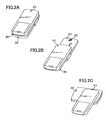
- Figs. 2A to 2C are perspective views of the portable device 1 seen from a rear.
- Fig. 2A shows a first position.
- Fig. 2B shows a second position.
- Fig. 2C shows a third position.
- the portable device 1 is portable device of which operation member is capable of being slid and stored such as a cellular phone, for example, and is constituted of a first enclosure 10, a second enclosure 20 and a third enclosure 30.
- the first enclosure 10 is in a substantially rectangular parallelepiped shape, where a first operation part 11 constituted of a television operation button, a moving image reproduction button, a sound volume button and the like is placed.
- the second enclosure 20 is also in a substantially rectangular parallelepiped shape as the first enclosure 10, where a rectangular display 21 for displaying information such as an image, with a longitudinal direction aligned with a longitudinal direction of the enclosure, and speakers 26R and 26L outputting sound are placed, and an image-taking lens 27 located on a back side of the enclosure as shown in Fig. 2B is placed.
- a rectangular display 21 for displaying information such as an image, with a longitudinal direction aligned with a longitudinal direction of the enclosure, and speakers 26R and 26L outputting sound are placed, and an image-taking lens 27 located on a back side of the enclosure as shown in Fig. 2B is placed.
- the third enclosure 30 is in a substantially rectangular parallelepiped shape as the first enclosure 10, and in the third enclosure 30, a second operation part 31 constituted of a call button, a clearing button, a ten key, a shutter button and the like, and a microphone 39 which inputs voice at the time of telephone call are placed.
- FIG. 3 is a system block diagram of the portable device 1.
- the first enclosure 10 includes a first detection switch 16 for detecting which position of a first position, a second position and a third position the portable device 1 is in, a telephone antenna 101, a telephone control part 102 having a decoder, modulator and the like for transmitting and receiving a voice signal, a camera control part 103 taking an image of a subject via an image-taking lens 27, and digital-processing the taken image data, a recording part 104 in which taken data is stored, an television antenna 105, a television control part 106 including a tuner for receiving television, a decoder and the like, a storage part 107 including an attachable and detachable external media for storing moving image data, a moving image reproduction control part 108 including a signal processing circuit and the like for reproducing data of the moving image storage part 107, a system control part 109 selectively controlling each of the control parts, a main board 110 mounted with ICs and electronic components of these control parts, and a battery not shown, in addition to the first control part 11 shown in
- the second enclosure 20 includes a display control part 201 including a driver and the like for displaying letters and images on the display 21, a voice output control part 202 including an amplifier or the like amplifying an output signal and controlling the speaker 26, and a lens control part 203 for changing a focus and a diaphragm of the lens 27, in addition to the display 21 and the speaker 26 shown in Fig. 1A and the image-taking lens 27 shown in Fig. 2B , and these ICs and electronic components are connected to the main board 110 by a flexible printed board not shown.
- the third enclosure 30 is provided with a second detection switch 36 for detecting which position of the first position, the second position and the third position the portable device 1 is in, in addition to the second operation part 31 and the microphone 39 shown in Fig. 1B , and these ICs and electronic components are connected to the main board 110 by a flexible printed board not shown.
- the portable device 1 thus configured can perform a call to an optional number, transmission and reception of an electronic mail and the like by using the second operation part 31 in the second position shown in Fig. 1B .
- the microphone 39 In the second position, the microphone 39 is exposed, and its positional relationship is such that the microphone 39 is separated at a distance convenient for a call, whereby call is possible by using the telephone function by applying the speaker 26 and the microphone 39 to an ear and a mouth respectively, and favorable operability is provided.
- the image-taking lens 27 is exposed, and by operating a shutter button of the operation part 31 with the lens pointed to a subject, whereby, image-taking is possible.
- the image-taking lens 27 is not exposed in the first position and the third position, and therefore, the image-taking lens can be protected when it is not used.
- the display 21 is horizontally oriented, and an image of a horizontally oriented television broadcasting can be efficiently displayed.
- the first operation part 11 exposed in the third position includes an operation button exclusive for viewing and listening to television and moving images, and is convenient for use.
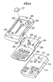
- Fig. 4 is an exploded perspective view of the portable device 1, where the second enclosure 20 is illustrated so that the bottom surface can be seen from the top portion by omitting the display 21 and the like.
- the first enclosure 10 is provided with a key 12 in a rectangular parallelepiped shape, a first lock pin 13, a first detection switch 16 for detecting whether the first lock pin 13 is pressed or not, and a second lock pin 15.
- the third enclosure 30 is provided with a round hole 32 for rotation, a third lock pin 33, a fourth lock pin 35, a second detection switch 36 for detecting whether the fourth lock pin 35 is pressed or not, a third round hole 37, and restriction plates 38 on both sides.
- the key 12 is rotatable inside the round hole 32 for rotation, and the hole diameter of the third round hole 37 is larger than the diameters of the first lock pin 13 and the second lock pin 15 so that the first lock pin 13 and the second lock pin 15 are fittable in it.
- the height of the restriction plates 38 is smaller than the thickness of the second enclosure 20.
- a keyhole-shaped slit 22, a first round hole 23, a second round hole 24, and a round hole 25 for a lens for disposing a lens for image-taking are provided on a bottom surface portion of the second enclosure 20.
- the hole diameters of the first round hole 23 and the second round hole 24 are larger than the diameters of the third lock pin 33 and the fourth lock pin 35 so that the third lock pin 33 and the fourth lock pin 35 are fittable therein.
- the keyhole-shaped slit 22 is formed into a shape in which a round hole portion and a long hole portion are connected.
- the key 12 is rotatable inside the round hole portion, whereas the key 12 is slidable inside the long hole portion, and the width of the long hole portion is formed to be smaller than the key 12 in the long surface direction.
- the key 12 provided on the first enclosure 10 is fitted and fixed to a slipping-off prevention cap 17 through the round hole 32 for rotation of the third enclosure and the keyhole-shape slit 22 of the second enclosure.
- the diameter of the slipping-off prevention cap 17 is larger than the round hole 32 for rotation and the round hole portion of the keyhole-shaped slit 22.
- Figs. 5A to 5D are views of the respective enclosures of the portable device 1 seen from the top surface.
- Fig. 5A shows the state of the second enclosure 20 seen from the top surface, and shows the keyhole-shaped slit 22, the first round hole 23 and the second round hole 24 are shown by omitting the display 21 and the like as in Fig. 4 .
- the round hole 25 for a lens is omitted here.
- Fig. 5B shows the state of the third enclosure 30 seen from the top surface, and shows the round hole 32 for rotation, the third lock pin 33, the fourth lock pin 35, the third round hole 37, and the restriction plates 38.
- Fig. 5C shows the state of the first enclosure 10 seen from the top surface, and shows the key 12, the first lock pin 13 and the second lock pin 15.
- the slipping-off prevention cap 17 fitted and fixed to the key 12 is omitted here.
- Fig. 5D is a view of the first position that is the state in which the third enclosure 30 is overlaid on the first enclosure 10, and the second enclosure 20 is further overlaid on the third enclosure 30, that is, the stored state seen from the top surface.
- the second lock pin 15 and the third round hole 37 should be originally hidden behind the second enclosure 20 and invisible but are shown through the second enclosure 20 for convenience.
- the key 12 provided on the first enclosure penetrates through the round hole 32 for rotation provided on the third enclosure, and at the same time, the second lock pin 15 provided on the first enclosure is fitted in the third round hole 37 provided in the third enclosure.
- the second enclosure 20 is further overlaid on the third enclosure 30, the key 12 which penetrates through the round hole 32 for rotation penetrates through the round hole portion of the keyhole-shaped slit 22 provided in the second enclosure, and at the same time, the third lock pin 33 provided in the third enclosure is fitted in the first round hole 23 provided in the second enclosure. Further, the slipping-off prevention cap 17 not shown here is fitted and fixed to the key 12.
- the first enclosure 10 and the second enclosure 20 are integrated to sandwich the third enclosure 30, and this position can be maintained by fitting of the lock pin and the round hole.
- the first lock pin 13 provided in the first enclosure 10 is pressed by the bottom surface portion of the third enclosure 30, and therefore, the first detection switch 16 provided at the lower portion of the first lock pin 13 is in an ON state.
- the fourth lock pin 35 provided in the third enclosure 30 is pressed by the bottom surface portion of the second enclosure 20, and therefore, the second detection switch 36 provided at the lower portion of the fourth lock pin 35 is also in an ON state.
- Figs. 6A to 6C are views of transition of slide movement of the portable device 1 to the second position from the first position seen from the top surface. Concerning the second enclosure 20, a bottom surface is in a visible state by omitting the display 21 and the like, and the slipping-off prevention cap 17 is also omitted.
- Figs. 7A to 7C are sectional views along the lines a to a' in Figs. 6A to 6C .
- Fig. 6A is a top view of the first position
- Fig. 7A is a sectional view taken in the line a to a' in Fig. 6A .
- the fourth lock pin 35 provided in the third enclosure 30 is invisible from the top surface, but is shown through the top surface for convenience. Since the fourth lock pin 35 is pressed by the back surface of the second enclosure 20 as shown in Fig. 7A , the second detection switch 36 is turned ON, and the third lock pin 33 is fitted in the first round hole 23.
- Fig. 6B shows the state in which the second enclosure 20 is slid to move to the upper portion in the drawing from the state of Fig. 6A
- Fig. 7B is a sectional view taken in the line a to a' of Fig. 6B .
- fitting of the first round hole 23 and the third lock pin 33 is released, and the second enclosure 20 slides to move to the upper portion in such a manner as to be guided by the restriction plates 38 provided in the third enclosure.
- the third lock pin 33 cannot be seen from the top surface, but is shown through the top surface for convenience here.
- the third enclosure 30 is provided with only the round hole 32 for rotation, and does not have a long hole portion like the keyhole-shaped slit 22 of the second enclosure 20, and therefore, cannot slide to move to the upper portion as the second enclosure 20. Therefore, the third enclosure 30 maintains the state integrated with the first enclosure 10 by fitting of the second lock pin 15 and the third round hole 37, and only the second enclosure 20 can slide to move in the upper direction.
- Fig. 7C shows a view showing that the second enclosure 20 is further slid to move to the upper portion in the drawing from the state of Fig. 7B , and is in the second position which is the state in which the display portion is used in the vertical orientation
- Fig. 7C is a sectional view in the line a to a' in Fig. 6C .
- the key 12 is butted against the terminal end of the long hole portion of the keyhole-shaped slit 22, and further sliding movement from it is restrained, and at the same time, the second round hole 24 provided in the second enclosure and the fourth lock pin 35 provided in the third enclosure are fitted to be able to maintain this position.
- the second operation part 31 provided on the third enclosure 30 is exposed, and the second operation part 31 can be used in the state in which the display 21 is seen in the vertical direction.
- the fourth lock pin 35 is fitted in the second round hole 24, and therefore, the second detection switch 36 provided at the lower portion of the fourth lock pin 35 is in the OFF state.
- the positional relationship of the first enclosure 10 and the third enclosure 30 does not change, and therefore, the first detection switch 16 not shown remains in the ON state.
- the second enclosure 20 can be easily returned to the first position from the second position by sliding and moving the second enclosure 20 to the lower portion in the drawing.
- Figs. 8A to 8C are views of the transition of the rotational movement of the portable device 1 to the third position from the first position seen from the top surface.
- the bottom surface is in a visible state by omitting the display 21 and the like, and the slipping-off prevention cap 17 is omitted.
- Figs. 9A to 9C are sectional views in the lines b to b' in Figs. 8A to 8C .
- Fig. 8A is a top view of the first position
- Fig. 9A is a sectional view in the line b to b' in Fig. 8A .
- the first lock pin 13 provided in the first enclosure 10 cannot be seen from the top surface, but it is shown through the top surface for convenience.
- the first round hole 23 and the third lock pin 33 are fitted to each other, and similarly, the third round hole 37 and the second lock pin 15 are fitted to each other.
- Fig. 8B is a view showing the state in which the third enclosure 30 is rotated counterclockwise from the state of Fig. 8A
- Fig. 9B is a sectional view in the line b to b' of Fig. 8B .
- fitting of the third round hole 37 and the second lock pin 15 is released, and the third enclosure 30 rotationally moves around the round hole 32 for rotation through which the key 12 penetrates.
- the restriction plates 38 are provided on both sides of the third enclosure 30, and therefore, when the third enclosure 30 is rotationally moved, the second enclosure 20 also rotationally moves integrally with the third enclosure.
- Fig. 8C is a view showing that the third enclosure 30 is further rotated counterclockwise from the state of Fig. 8B , and is in the third position in which the display device is used in the horizontal orientation
- Fig. 8C is a sectional view in the line b to b' in Fig. 9C .
- the third round hole 37 provided in the third enclosure 30 is fitted to the first lock pin 13 provided in the first enclosure 10 to be able to maintain this position.
- the first operation part 11 provided in the first enclosure 10 is exposed in the state in which the display 21 provided in the second enclosure 20 is rotationally moved to the upper portion, and the first operation part 11 can be used with the display 21 seen in the horizontal direction.
- the first lock pin 13 is fitted in the third round hole 37, and therefore, the first detection switch 16 provided at the lower portion of the first lock pin 13 is in the OFF state. Since the positional relationship of the third enclosure 30 and the second enclosure 20 does not change, the second detection switch 36 not shown remains in the ON state. Counterclockwise rotation of the third enclosure 30 is restricted to the 90 degrees by a stopper not shown, and therefore, the third enclosure 30 does not rotate more than 90 degrees.
- the portable device can be easily returned to the first position from the third position by rotationally moving the third enclosure 30 clockwise.
- the second enclosure 20 rotates integrally with the third enclosure 30 by the restriction plates 38.
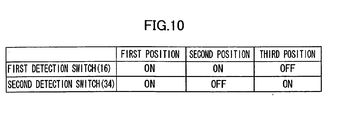
- Fig. 10 is a table showing an ON/OFF state of the first detection switch 16 and the second detection switch 34 at each position, and as described above, the combination of ON and OFF differs in accordance with each position.
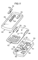
- Fig. 11 is a flowchart showing an operation state of the portable device 1.
- the system control part 109 determines which state the portable device 1 is in based on ON/OFF information of the first detection switch 16 and the second detection switch 34. First, the system control part 109 determines whether the portable device 1 is in the first position or not (step S1). When it determines that the portable device is in the first position, it makes inputs of the first operation part 11 and the second operation part 31 invalid and brings the display 21 into a non-display state at the same time (step S2), and reduces power consumption. The system control part 109 maintains the state until it determines that the position is shifted to another position.
- the portable device In the first position, the portable device is in a call waiting mode, and arrival of a telephone call and reception of an electronic mail are possible by the system control part 109 operating the telephone control part 102. Thereafter, in any mode, arrival of a telephone call and reception of an electronic mail are possible.
- step S3 determines whether the portable device is in the second position or in the third position next.
- step S4 determines whether the portable device is in the third position here, it makes the first operation part 11 valid, and causes the display 21 to display horizontally (step S4).
- the system control part 109 sets the portable device 1 in a television viewing and listening mode (step S5), and causes the television control part 106 to operate to make television viewing and listening possible. Since at this time the first operation part 11 suitable for television viewing and listening is exposed and the operation is valid, channel switching, volume adjustment and the like are possible by using the first operation part 11.
- the system control part always monitors the first detection switch 16 and the second detection switch 34 (step S6), and when it determines that the position shifts to the first position, it makes the first operation part 11 invalid and stops display on the display (step S2).
- step S7 it is possible to shift the portable device to a moving image reproduction mode from a television viewing and listening mode by using the first operation part 11 (step S7).
- the mode switching may be performed by inserting external media into the storage part 107.
- the system control part 109 sets the portable device 1 in the moving image reproduction mode (step S8), stops the television control part 106 and operates the moving image reproduction control part 108 to enable moving image reproduction.
- the first operation part 11 suitable for moving image reproduction is exposed as in the television viewing and listening mode, and the input is made valid. Therefore, start, stop and temporary stop of reproduction, volume adjustment and the like are possible by using the first operation part 11.
- the system control part always monitors the first detection switch 16 and the second detection switch 34 (step S9), and when it determines that the portable device shifts to the first position, it makes the first operation part 11 invalid, and stops the display on the display (step S2).
- step S10 It is possible to shift the portable device to the television viewing and listening mode from the moving image reproduction mode (step S10), and when mode switching is performed, the system control part 109 sets the portable device 1 in the television viewing and listening mode (step S5), and stops the moving image reproduction control part 108 and operates the television control part 106 to enable television viewing and listening.
- the system control part 109 determines that the portable device is in the second position in step S3, it makes the second operation part 31 valid and allows the display 21 to display in the vertical orientation (step S11).
- the system control part 109 sets the portable device 1 in the call mode (step S12), and controls the telephone control part 102, whereby a call to an optional number, transmission of an electronic mail, address book search and the like are enabled in addition to arrival of a telephone call and reception of an electronic mail which are possible in all the modes. Since at this time, the second operation part 31 suitable for the telephone function is exposed, and the input is valid, favorable usability is obtained.
- the system control part always monitors the first detection switch 16 and the second detection switch 34 (step S13), and when the system control part determines that the portable device shifts to the first position, it makes input of the second operation part 31 invalid, and brings the display 21 into a non-display state (step S2).
- step S15 It is possible to shift the portable device to a camera mode from the call mode by using the second operation part 31 (step S15).
- the system control part 109 sets the portable device 1 in the camera mode (step S15), controls the telephone control part 102 to limit the telephone function only to arrival of a telephone call and reception of an electronic mail, and operates the camera control part 103 to enable image-taking.
- the second operation part 31 suitable for image-taking is exposed as in the call mode, and the input is valid. Therefore, image-taking mode switching, zoom adjustment and actual image-taking are possible by using the second operation part 31.
- the system control part 109 always monitors the first detection switch 16 and the second detection switch 34 as in the call mode (step S16). When the system control part 109 determines that the portable device shifts to the first position, it makes the second operation part 31 invalid and brings the display 21 into a non-display state (step S2).
- step S17 it is possible to shift the portable device to the call mode from the camera mode (step S17), and when mode switching is performed, the system control part 109 sets the portable device 1 in the call mode (step S12), and stops the camera control part 103 and controls the telephone control part 102 to enable a call and electronic mail transmission.
- Fig. 12 is an exploded perspective view of the third enclosure 30.
- the third enclosure 30 includes a top surface part 30a including the second operation part 31, the third lock pin 33, the fourth lock pin 35 and the restriction plates 38, a membrane switch 90 and a lower surface part 30b, and is configured so that the top surface part 30a and the lower surface part 30b sandwich the membrane switch 90.
- the membrane switch 90 connects to the main board 110 of the first enclosure 10 by using a flexible printed board not shown as the signals of the second detection switch 36 and the microphone 39.
- a flexible printed board not shown as the signals of the second detection switch 36 and the microphone 39.
- the third enclosure 30 is not limited to the embodiment, and may be configured as shown in Fig. 13 .
- the third enclosure 30 shown in Fig. 13 includes only key tops of the operation buttons, and when the key top is pressed, the key shaft projects from a hole portion for a key shaft provided in the bottom surface portion of the third enclosure 30.
- Fig. 13 is an exploded perspective view of the third enclosure 30.
- the third enclosure 30 includes the top surface part 30a including the third lock pin 33, the fourth lock pin 35 and the restriction plates 38, the lower surface part 30b including the hole portions for key shafts, and a key top group 130, and is configured so that the top surface part 30a and the lower surface part 30b sandwich the key top group 130.
- Fig. 14 is a sectional view of the second operation part 31 of the third enclosure and the first operation part 11 of the first enclosure 10 in the second position.
- the positional relationship of the operation buttons of the second operation part 31 and the first operation part 11 has the configuration as shown in Fig. 14 .
- the first key top 131 of the second operation part 31 is disposed directly above a first operation button 111 of the first operation part 11, and the second key top 132 of the second operation part 31 is disposed directly above a second operation button 112 of the first operation part 11.
- the key shaft of the first key top 131 presses the first operation button 111 through the hole portion for the key shaft, and by the user pressing the second key top 132, the operation of the key shaft of the second key top 132 pressing the second operation button 112 through the round hole for the key shaft becomes possible.
- the system control part 109 can determine which position of the second position and the third position the portable device is in by the ON/OFF state of the position detection switch in advance as shown in Fig. 9 , and therefore, it can distinguish whether the input of the first operation button 111 is the input made by directly pressing the first operation button 111 or the input made by pressing the first operation button 111 made by pressing the first key top 131.
- a third key top 133 including two key shafts and hole portions for key shafts with one operation button directly above a third operation button 113a and a fourth operation button 113b of the first operation part 11.
- the key shaft of the third key top 133 presses the third operation button 113a through the round hole for the key shaft when the left side of the third key top 133 is pressed
- the key shaft of the third key top 133 presses the fourth operation button 113b through the round hole for the key shaft when the right side of the third key top 133 is pressed
- the key shafts of the third key top 133 press both the third operation button 113a and the fourth operation button 113b through the round holes for the key shafts when the center of the third key top 133 is pressed, and they can be assigned to different functions respectively.
- the portable device can be brought into the use state from the stored state by one action, the orientation of the display can be changed in correspondence with the use purpose, and the operation part corresponding to the use purpose can be used. Therefore, portable device with high usability can be realized.
- the portable device 1 of a second embodiment according to the present invention will be described by using Figs. 15 to 20 .
- the same reference numerals are given to the parts common to the first embodiment, and the detailed description of them will be omitted.
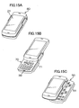
- Figs. 15A to 15C are perspective views of the portable device 1 of the second embodiment according to the present invention seen from the front.
- Fig. 15A shows the first position that is the stored state.
- Fig. 15B shows the second position that is a state of using the display device in a vertical orientation.
- Fig. 15C shows the third position that is a state of using the display device in a horizontal orientation.
- operation buttons for the telephone and camera are placed
- a first operation part 51 shown in Fig. 15C operation buttons for TV viewing and listening and moving image reproduction are placed.
- Figs. 16A to 16C are perspective views of the portable device 1 seen from the rear side.
- Fig. 16A shows the first position.
- Fig. 16B shows the second position.
- Fig. 16C shows the third position.
- an image-taking lens 27 is placed on a rear surface portion of a second enclosure 60.
- Fig. 17 is an exploded perspective view of the portable device 1, and the second enclosure 60 is illustrated so that a bottom surface is seen from a top portion by omitting a display 21 and the like as in the description of the first embodiment.
- Reference numeral 52 denotes a parallel-linking mechanism constituted of a link arm 52a and a plate 52b
- reference numerals 53 and 54 denote a first projection portion and a second projection portion provided on a plate 52b.
- a fifth lock pin 56 and a sixth lock pin 57 are placed on the first enclosure 50, in addition to a fifth round hole 55 provided in the link arm 52a.
- a first lock spring 63, a second lock spring 64 and a rail groove 65 are placed on the second enclosure 60.
- a first round hole 73 and a second round hole 74 are placed in a third enclosure 70, and are respectively fitted to the first projection portion 53 and the second projection portion 54 provided on the plate 52b, and thereby, the first enclosure 50 and the third enclosure 70 are integrated.
- a rail 75 is fitted in a rail joining groove 76 to sandwich the second enclosure 60, and thereby, the second enclosure 60 and the third enclosure 70 are integrated.
- the portable device 1 of the second embodiment according to the present invention has the constitution in which the first enclosure 50, the second enclosure 60 and the third enclosure 70 are integrated.
- Figs. 18A, 18B and 18C are views of the respective enclosures seen from top portions.
- Fig. 18A is a view of the second enclosure 60 seen from the top portion, and shows the first lock spring 63, the second lock spring 64 and the rail groove 65, but omits the round hole 25 for a lens.
- Fig. 18B is a view of the third enclosure 70 seen from the top portion, and shows the restriction plates 38 and the rail 75.
- Fig. 18C is a view of the first enclosure 50 seen from the top portion, and shows the fifth round hole 55 provided in the link arm, the fifth lock pin 56 and the sixth lock pin 57 provided on the first enclosure 50, in addition to the parallel-linking mechanism 52, with the fifth hole 55 for lock and the fifth lock pin 56 fitted to each other.
- Figs. 19A to 19D are views of transition of vertical slide movement of the portable device 1 from the first position that is a stored state to the second position that is a state of using the display device in a vertical orientation seen from the top side, and as for the second enclosure 60, the bottom surface is visible from the top portion by omitting the display 21 and the like.
- Fig. 19A is a view of the state of the first position seen from the top side, and the first lock spring 63 provided in the second enclosure 60 engages with a V groove (see Fig. 17 ) formed at a side portion of the rails 75 joined to the third enclosure 70.
- Fig. 19B is a view showing a state in which the second enclosure 60 is slid to move to the upper portion of the drawing from the state of Fig. 19A .
- engagement of the first lock spring 63 and the V groove of the rail 75 is released, and the second enclosure 60 slides to move straight to the upper portion by being guided by the restriction plates 38 at both sides of the third enclosure 70.
- the third enclosure 70 is joined to the first enclosure 50 by the parallel-linking mechanism 52, and cannot slide and move to the upper portion together with the second enclosure 60. Therefore, the third enclosure 70 remains to be integrated with the first enclosure 50, and only the second enclosure 60 can slide and move.
- Fig. 19C is a view showing that the second enclosure 60 is further slid and moved to the upper portion of the drawing from the state of Fig. 19B , and the portable device is in the second position that is the state of using the display device in the vertical orientation.
- the rail 75 butts against a terminal end of the rail groove 65 to restrict further slide movement from it, and at the same time, the second lock spring 64 and the V groove of the rail 75 are engaged with each other, and can maintain this position.
- the position detecting mechanism not shown detects that the portable device is in the second position, and the system control part 109 makes the display of the display 21 in a vertical direction to make the second operation part 71 usable.
- the second operation part 71 provided in the third enclosure 70 is exposed in the state in which the display 21 provided in the second enclosure 20 is slid and moved to the upper portion, and the second operation part 71 can be used with the display 21 seen in the vertical direction.
- the telephone function and camera function are usable, and as described above, the second operation part 71 becomes the operation part for a telephone and a camera as described above.
- the portable device can be easily returned to the first position from the second position by sliding and moving the second enclosure 60 to the lower portion of the drawing. At this time, the rail 75 is released from the engagement with the second lock spring 64, and engages with the first lock spring 63 to return to the first position.
- a position detecting mechanism not shown, it is detected that the portable device is in the first position, the input of the second operation 71 is made invalid, and the display 21 is brought into a non-display state.
- Figs. 20A to 20C are views of the transition of the horizontal slide movement of the portable device 1 from the first position to the third position seen from the top side, and the second enclosure 60 is omitted.
- Fig. 20A is a view of the state of the first position seen from the top side.
- the parallel-linking mechanism and the lock spring included in the first enclosure 50 are not originally seen from the top side, but are shown through the top for convenience.
- the fifth round hole 55 provided in the link arm 52a and the fifth lock pin 56 provided in the first enclosure are fitted to each other, and the state in which the first enclosure and the third enclosure are integrated is maintained.
- Fig. 20B is a view showing the state in which the third enclosure 70 is slid and moved in the left direction from the state of Fig. 20A .
- fitting of the fifth round hole 55 and the fifth lock pin 56 is released, and the third enclosure 70 moves along the circular arc drawn by the link arm.
- the second enclosure 60 and the third enclosure 70 the second enclosure 60 slides and moves while remaining to be integrated with the third enclosure 70 by engagement of the rail 75 and the first lock spring 63 and the restriction plates 38.
- Fig. 20C is a view showing that the third enclosure 70 is further moved to the left from the state of Fig. 20B , and is in the third position that is the state of using the display device in the horizontal orientation. In this state, the fifth round hole 55 and the sixth lock pin 57 are fitted to each other, and the position can be maintained. Movement of the third enclosure 70 is restricted to the third position by the stopper not shown, and therefore, the third enclosure 70 does not move to the left side from the third position.
- the system control part 109 detects that the portable device is in the third position by the position detecting mechanism not shown, and the system control part 109 makes the display of the display 21 in the horizontal orientation, and makes the first operation part 51 usable.
- the first operation part 51 provided in the first enclosure 50 is exposed in the state in which the display 21 provided in the second enclosure 60 is slid and moved to the left portion, and by tilting the entire device at 90 degrees, the first operation part 51 can be used in the state in which the display 21 is seen in the horizontal direction. In the third position, the TV viewing and listening function and the moving image reproducing function are usable. As described above, the first operation part 51 is the operation part for TV viewing and listening and moving image reproduction.
- the system control part detects that the portable device is in the first position by the position detecting mechanism not shown, makes the first operation part 51 invalid, and brings the display 21 into a non-display state.
- the image-taking lens 27 is exposed, and by pointing the lens to a subject, and operating the button for camera operation, image-taking is possible.
- the image-taking lens 27 is not exposed in the first position and the third position, and therefore, the image-taking lens can be protected when the lens is not used.
- the slit mechanism is used for slide movement to the second position from the first position, and the parallel-linking mechanism is used for slide movement to the third position from the first position.
- the parallel-linking mechanism may be used for slide movement to the second position from the first position, and the slit mechanism may be used for slide movement to the third position from the first position.
- the slide movement to the second position from the first position and the slide movement to the third position from the first position are not restricted respectively, and therefore, the slide movement of both of them can be performed at the same time, but in this case, the operation of the position which the position detecting mechanism first detects is performed.
- a restriction mechanism may be provided so as to perform only slide movement of any one of them.
- the third enclosure 70 is integrated with the first enclosure 50 and fixed with the slide movement to the second position from the first position, and only the second operation part 71 provided on the third enclosure 70 is exposed in the second position.
- the third enclosure 70 may be constituted to move integrally with the first enclosure 50 partway to expose part of the first enclosure 50, as long as the different operation parts are operable respectively in the second position and the third position.
- Fig. 21A is a view showing the second position that is the state in which part of the first enclosure 50 is exposed.
- An operation member may be provided on the exposed part of the first enclosure 50, and in this case, an operation member may be provided as long as the different operation parts are operable respectively in the second position and the third position.
- the third enclosure 70 is integrated with the second enclosure 60 and fixed, and in the third position, only the first operation part 51 provided on the first enclosure 50 is exposed.
- the third enclosure 70 is completely integrated with the second enclosure 60 and does not move with the slide movement of the first enclosure 50 to the third position from the first position, part of it covers the surface of the first enclosure, and a part of the third enclosure 70 is exposed, the same operation can be obtained as long as the different operation parts are respectively operable in the second position and the third position.
- Fig. 21B is a view showing the third position that is the state in which part of the third enclosure 70 covers the first enclosure 50 and part of the third enclosure 70 is exposed.
- An operation member may be also provided on the exposed part of the third enclosure as long as the different operation parts are operable in the second position and the third position in this case.
- the second operation part 71 may be eliminated in the third enclosure 70, and in the second position in this case, the third enclosure 70 plays a role of covering the first operation part 51.
- the microphone 39 is exposed, the positional relationship of the speaker 26 and the microphone 39 is such that they are separated at a distance favorable for a call, and the speaker 26 and the microphone 39 are applied to an ear and a mouth respectively, whereby the constitution with favorable usability in the telephone function is provided.
- the first operation part 51 may be eliminated from the first enclosure 50, and in the third position in this case, by tilting the entire device at 90 degrees and by holding the first enclosure 50 by hand in the sate in which the display 21 is seen in the horizontal direction, the constitution easy to hold is provided.
- the portable device 1 of the third embodiment according to the present invention has the same constitution as in the second embodiment, but differs from the second embodiment in the point that in the third position which is the state of using the display in the horizontal orientation, a game function is usable, and a first operation part 81 provided in a first enclosure 80 is the operation part for game.
- the portable device 1 of the fourth embodiment according to the present invention has the same constitution as the second embodiment, but differs from the second embodiment in the point that in the third position which is the state of using the display in the horizontal orientation, a PDA function is usable, and a first operation part 83 provided in a first enclosure 82 is a full keyboard.
Landscapes
- Engineering & Computer Science (AREA)
- Signal Processing (AREA)
- Computer Networks & Wireless Communication (AREA)
- Telephone Set Structure (AREA)
- Telephone Function (AREA)
- Fittings On The Vehicle Exterior For Carrying Loads, And Devices For Holding Or Mounting Articles (AREA)
- Devices For Indicating Variable Information By Combining Individual Elements (AREA)
Applications Claiming Priority (1)
| Application Number | Priority Date | Filing Date | Title |
|---|---|---|---|
| JP2006327446A JP4852403B2 (ja) | 2006-12-04 | 2006-12-04 | 携帯機器 |
Publications (3)
| Publication Number | Publication Date |
|---|---|
| EP1931118A2 true EP1931118A2 (de) | 2008-06-11 |
| EP1931118A3 EP1931118A3 (de) | 2008-08-06 |
| EP1931118B1 EP1931118B1 (de) | 2017-10-11 |
Family
ID=39264537
Family Applications (1)
| Application Number | Title | Priority Date | Filing Date |
|---|---|---|---|
| EP07254676.5A Not-in-force EP1931118B1 (de) | 2006-12-04 | 2007-12-03 | Tragbare vorrichtung bestehend aus drei beweglichen gehäuseteilen |
Country Status (5)
| Country | Link |
|---|---|
| US (1) | US20080132288A1 (de) |
| EP (1) | EP1931118B1 (de) |
| JP (1) | JP4852403B2 (de) |
| KR (1) | KR100950709B1 (de) |
| CN (1) | CN101197861B (de) |
Cited By (7)
| Publication number | Priority date | Publication date | Assignee | Title |
|---|---|---|---|---|
| EP2312811A1 (de) * | 2009-10-13 | 2011-04-20 | Research In Motion Limited | Tragbare elektronische Vorrichtung mit einem Schiebe- und Drehmechanismus |
| US8332000B2 (en) | 2009-10-13 | 2012-12-11 | Research In Motion Limited | Handheld electronic device having a slide-and-twist mechanism |
| US8514179B2 (en) | 2010-12-23 | 2013-08-20 | Research In Motion Limited | Handheld electronic communication device having an age compensating display |
| US8532721B2 (en) | 2010-12-23 | 2013-09-10 | Blackberry Limited | Portable electronic device having sliding display providing event notification |
| US8711099B2 (en) | 2010-05-10 | 2014-04-29 | Blackberry Limited | Handheld electronic communication device having sliding display |
| US8723890B2 (en) | 2010-12-23 | 2014-05-13 | Blackberry Limited | Handheld electronic device having sliding display and position configurable camera |
| WO2020125273A1 (zh) * | 2018-12-17 | 2020-06-25 | 维沃移动通信有限公司 | 终端设备 |
Families Citing this family (74)
| Publication number | Priority date | Publication date | Assignee | Title |
|---|---|---|---|---|
| USD581894S1 (en) * | 2007-08-09 | 2008-12-02 | Lg Electronics Inc. | Mobile phone |
| USD592167S1 (en) * | 2007-11-15 | 2009-05-12 | Lg Electronics Inc. | Mobile phone |
| USD580401S1 (en) * | 2007-11-26 | 2008-11-11 | Samsung Electronics Co., Ltd. | Mobile phone |
| TWD134567S1 (zh) * | 2007-12-31 | 2010-04-21 | Lg電子股份有限公司 | 行動電話 |
| CA126551S (en) * | 2008-02-08 | 2009-05-01 | Toshiba Kk | Portable information terminal |
| TWD134168S1 (zh) * | 2008-03-24 | 2010-04-01 | 東芝股份有限公司 | 攜帶型資訊終端機 |
| USD596601S1 (en) * | 2008-04-15 | 2009-07-21 | Motorola, Inc. | Communication device |
| USD601994S1 (en) * | 2008-06-11 | 2009-10-13 | Lg Electronics Inc. | Cellular phone |
| USD594841S1 (en) * | 2008-06-12 | 2009-06-23 | Samsung Electronics Co., Ltd. | Portable phone |
| EP2337314B1 (de) | 2008-10-10 | 2015-10-07 | NEC Corporation | Mobiles endgerät, steuerverfahren für das mobile endgerät und aufzeichnungsmedium |
| USD618646S1 (en) * | 2008-10-23 | 2010-06-29 | Microsoft Corporation | Handset |
| USD603356S1 (en) * | 2008-11-19 | 2009-11-03 | Samsung Electronics Co., Ltd. | Portable telephone |
| USD602463S1 (en) * | 2008-11-21 | 2009-10-20 | Nokia Corporation | Handset |
| USD611041S1 (en) * | 2008-11-21 | 2010-03-02 | Nokia Corporation | Handset |
| USD607865S1 (en) * | 2008-12-04 | 2010-01-12 | Samsung Electronics Co., Ltd. | Mobile phone |
| USD615946S1 (en) * | 2009-01-23 | 2010-05-18 | Lg Electronics Inc. | Mobile phone |
| USD618200S1 (en) * | 2009-02-02 | 2010-06-22 | Lg Electronics Inc. | Mobile phone |
| USD611448S1 (en) * | 2009-02-03 | 2010-03-09 | Samsung Electronics Co., Ltd. | Mobile phone |
| US20100216513A1 (en) * | 2009-02-23 | 2010-08-26 | Research In Motion Limited | Handheld electronic device with rotatable member |
| USD612358S1 (en) * | 2009-03-04 | 2010-03-23 | Samsung Electronics Co., Ltd. | Mobile phone |
| USD619985S1 (en) * | 2009-03-17 | 2010-07-20 | Lg Electronics Inc. | Mobile phone |
| USD619984S1 (en) * | 2009-05-21 | 2010-07-20 | Samsung Electronics Co., Ltd | Mobile phone |
| USD619556S1 (en) * | 2009-05-26 | 2010-07-13 | Samsung Electronics Co., Ltd. | Mobile phone |
| EP2440961A1 (de) * | 2009-06-08 | 2012-04-18 | Commscope Inc. of North Carolina | Hochdichtes patching-system für kabel und optische faser |
| JP5363890B2 (ja) * | 2009-06-26 | 2013-12-11 | 京セラ株式会社 | 携帯電話機 |
| USD617755S1 (en) * | 2009-07-07 | 2010-06-15 | Nokia Corporation | Handset |
| USD619990S1 (en) * | 2009-08-06 | 2010-07-20 | Hon Hai Precision Industry Co., Ltd. | Mobile terminal |
| TWD140986S1 (zh) * | 2009-08-24 | 2011-06-11 | 新力易利信通訊公司 | 行動電話 |
| USD618201S1 (en) * | 2009-08-26 | 2010-06-22 | Kyocera Corporation | Mobile phone |
| USD617759S1 (en) * | 2009-08-28 | 2010-06-15 | Nokia Corporation | Handset |
| CA134912S (en) * | 2009-12-07 | 2010-12-30 | Sony Ericsson Mobile Comm Ab | Mobile phone |
| TWD141635S1 (zh) * | 2009-12-15 | 2011-07-21 | 新力易利信通訊公司 | 行動電話 |
| USD633063S1 (en) | 2009-12-18 | 2011-02-22 | Kyocera Corporation | Mobile phone |
| USD628184S1 (en) * | 2009-12-22 | 2010-11-30 | Samsung Electronics Co., Ltd. | Mobile phone |
| USD621380S1 (en) * | 2010-02-12 | 2010-08-10 | Samsung Electronics Co., Ltd. | Cellular phone |
| USD629779S1 (en) * | 2010-02-15 | 2010-12-28 | Motorola Mobility, Inc. | Communication device |
| US8284554B2 (en) * | 2010-02-15 | 2012-10-09 | Motorola Mobility Llc | Electronic device housing with pivoting and sliding portions |
| USD640221S1 (en) * | 2010-03-23 | 2011-06-21 | Lg Electronics Inc. | Mobile phone |
| CN102255986B (zh) * | 2010-05-20 | 2014-04-30 | 深圳富泰宏精密工业有限公司 | 旋转机构及具有该旋转机构的电子装置 |
| USD640224S1 (en) * | 2010-06-21 | 2011-06-21 | Sony Ericsson Mobile Communications Ab | Mobile phone |
| USD635115S1 (en) * | 2010-06-23 | 2011-03-29 | Fih (Hong Kong) Limited | Mobile phone |
| USD646254S1 (en) * | 2010-10-06 | 2011-10-04 | Samsung Electronics Co., Ltd. | Mobile phone |
| USD645836S1 (en) * | 2010-10-12 | 2011-09-27 | Samsung Electronics Co., Ltd. | Mobile phone |
| JP5636873B2 (ja) * | 2010-10-26 | 2014-12-10 | 富士通株式会社 | 筐体機構 |
| CL2011000719S1 (es) * | 2010-11-10 | 2011-09-02 | Sony Ericsson Mobile Communications Ab | Telefono movil de cuerpo de forma general plinto rectangular de vertices curvos en un radio menor, su cara anterior plana y su cara posterior plana formada por un manto concavo convexo extendido, en la cara anterior, se proyecta centrada con respecto a la altura y ancho, una proyecion rectangular lisa con sus vertices curvos. |
| USD654041S1 (en) * | 2010-12-17 | 2012-02-14 | Samsung Electronics Co., Ltd. | Mobile phone |
| USD651188S1 (en) * | 2010-12-21 | 2011-12-27 | Sony Ericsson Mobile Communications Ab | Mobile phone |
| USD651190S1 (en) * | 2011-02-02 | 2011-12-27 | Sony Ericsson Mobile Communications Ab | Mobile phone |
| TWD147564S1 (zh) * | 2011-02-02 | 2012-06-11 | 新力易利信通訊公司 | 行動電話 |
| USD663279S1 (en) * | 2011-05-12 | 2012-07-10 | Samsung Electronics Co., Ltd. | Mobile phone |
| JP2011183227A (ja) * | 2011-06-14 | 2011-09-22 | Takashi Chiba | 一体型囲碁盤 |
| USD662486S1 (en) * | 2011-07-26 | 2012-06-26 | Nokia Corporation | Handset |
| USD666980S1 (en) * | 2011-07-26 | 2012-09-11 | Nokia Corporation | Handset |
| USD672328S1 (en) * | 2011-10-14 | 2012-12-11 | Nokia Corporation | Handset |
| USD676009S1 (en) * | 2011-11-11 | 2013-02-12 | Kyocera Corporation | Portable terminal |
| USD713812S1 (en) * | 2012-11-22 | 2014-09-23 | Kyocera Corporation | Portable terminal |
| KR102003377B1 (ko) * | 2012-12-13 | 2019-07-24 | 삼성전자주식회사 | 슬립 모드에서 카메라 모듈을 구동하는 전자 장치 및 방법 |
| USD755748S1 (en) * | 2013-09-27 | 2016-05-10 | Lg Electronics Inc. | Mobile phone |
| USD756323S1 (en) * | 2013-10-04 | 2016-05-17 | Lg Electronics Inc. | Mobile phone |
| USD756948S1 (en) * | 2013-11-11 | 2016-05-24 | Lg Electronics Inc. | Cellular phone |
| USD756949S1 (en) * | 2013-11-11 | 2016-05-24 | Lg Electronics Inc. | Cellular phone |
| CN104660796A (zh) * | 2013-11-25 | 2015-05-27 | 青岛海尔通信有限公司 | 手机及其拍照控制方法 |
| USD757675S1 (en) * | 2014-02-03 | 2016-05-31 | Lg Electronics Inc. | Cellular phone |
| USD757674S1 (en) * | 2014-02-03 | 2016-05-31 | Lg Electronics Inc. | Cellular phone |
| USD783566S1 (en) * | 2015-04-23 | 2017-04-11 | Lg Electronics Inc. | Mobile phone |
| USD788753S1 (en) * | 2015-04-23 | 2017-06-06 | Lg Electronics Inc. | Mobile phone |
| USD784950S1 (en) * | 2015-06-30 | 2017-04-25 | Lg Display Co., Ltd. | Mobile phone |
| USD798282S1 (en) * | 2015-06-30 | 2017-09-26 | Lg Display Co., Ltd. | Mobile phone |
| USD801958S1 (en) * | 2015-06-30 | 2017-11-07 | Lg Display Co., Ltd. | Mobile phone |
| USD1015430S1 (en) * | 2020-05-13 | 2024-02-20 | Intellivision Entertainment LLC | Gaming console and gaming controller system |
| US12015719B1 (en) | 2023-09-13 | 2024-06-18 | Zecurity, Llc | Apparatus, systems, and methods relying on non-flashable circuitry for improving security on public or private networks |
| US12088735B1 (en) | 2023-09-13 | 2024-09-10 | Zecurity, Llc | Apparatus, systems, and methods relying on non-flashable circuitry for improving security on public or private networks |
| US12045350B1 (en) | 2023-09-13 | 2024-07-23 | Zecurity, Llc | Apparatus, systems, and methods relying on non-flashable circuitry for improving security on public or private networks |
| US12169589B1 (en) * | 2023-09-13 | 2024-12-17 | Zecurity, Llc | Apparatus and methods relying on non-flashable circuitry for improving security for a system connected to a public or private network |
Citations (7)
| Publication number | Priority date | Publication date | Assignee | Title |
|---|---|---|---|---|
| JP2001156893A (ja) | 1999-11-29 | 2001-06-08 | Nec Saitama Ltd | 通信機器の表示システム及び方法 |
| JP2002330198A (ja) | 2001-04-26 | 2002-11-15 | Kyocera Corp | 携帯電話機 |
| JP2005038217A (ja) | 2003-07-16 | 2005-02-10 | Nec Access Technica Ltd | 折り畳み式携帯装置 |
| US20050091431A1 (en) | 2003-10-23 | 2005-04-28 | Robert Olodort | Portable communication devices |
| EP1594289A2 (de) | 2004-05-03 | 2005-11-09 | Samsung Electronics Co., Ltd. | Doppelverschiebbares und tragbares Kommunikationsendgerät |
| US20060061552A1 (en) | 2004-09-20 | 2006-03-23 | Qualcomm Incorporated | Devices and methods for controlling relative movement between layers of an electronic device |
| US20060226150A1 (en) | 2005-03-14 | 2006-10-12 | Benq Corporation | Electronic device with two-dimensional sliding cover and two-dimensional slide apparatus |
Family Cites Families (16)
| Publication number | Priority date | Publication date | Assignee | Title |
|---|---|---|---|---|
| JP3139741B2 (ja) * | 1997-04-25 | 2001-03-05 | 日本電気株式会社 | 携帯無線情報端末装置 |
| US6397078B1 (en) * | 1999-08-27 | 2002-05-28 | Young S. Kim | Combined mobile telephone and personal digital assistant |
| JP4061473B2 (ja) * | 2002-04-26 | 2008-03-19 | 日本電気株式会社 | 折り畳み型携帯電話機 |
| US6766181B1 (en) * | 2002-08-30 | 2004-07-20 | Nokia Corporation | Folding mobile station with dual-movement hinge |
| JP4192024B2 (ja) * | 2003-04-17 | 2008-12-03 | 加藤電機株式会社 | 携帯端末用取付装置 |
| US7058433B2 (en) * | 2003-11-06 | 2006-06-06 | Sony Ericsson Mobile Communications Ab | Mechanism for ergonomic integration of a digital camera into a mobile phone |
| WO2005052777A2 (en) * | 2003-11-19 | 2005-06-09 | Qualcomm Incoporated | A portable device with versatile keyboards |
| KR100704031B1 (ko) * | 2004-04-29 | 2007-04-04 | 삼성전자주식회사 | 이중 슬라이딩 타입 휴대용 통신 장치 |
| KR100675360B1 (ko) * | 2005-01-07 | 2007-01-29 | 삼성전자주식회사 | 슬라이드형 이동통신 단말기 |
| US7158817B2 (en) * | 2005-03-17 | 2007-01-02 | Masaharu Kubo | Portable terminal |
| KR100709808B1 (ko) * | 2005-03-31 | 2007-04-23 | 주식회사 팬택 | 회전 슬라이드형 이동통신 단말기 |
| KR20070050128A (ko) * | 2005-11-10 | 2007-05-15 | 주식회사 팬택 | 슬라이드 파트 및 스윙 파트를 포함하는 개인휴대단말기 |
| JP2007179525A (ja) * | 2005-11-30 | 2007-07-12 | Casio Comput Co Ltd | 携帯型電子機器 |
| KR100743093B1 (ko) * | 2005-12-21 | 2007-07-27 | 주식회사 팬택 | 디스플레이 파트 및 키 패드 파트를 포함하는개인휴대단말기 |
| JP2007300310A (ja) * | 2006-04-28 | 2007-11-15 | Matsushita Electric Ind Co Ltd | 携帯型端末の筐体構造 |
| JP2008131454A (ja) * | 2006-11-22 | 2008-06-05 | Casio Hitachi Mobile Communications Co Ltd | 携帯電子機器 |
-
2006
- 2006-12-04 JP JP2006327446A patent/JP4852403B2/ja not_active Expired - Fee Related
-
2007
- 2007-12-03 EP EP07254676.5A patent/EP1931118B1/de not_active Not-in-force
- 2007-12-04 CN CN2007101959241A patent/CN101197861B/zh not_active Expired - Fee Related
- 2007-12-04 US US11/987,726 patent/US20080132288A1/en not_active Abandoned
- 2007-12-04 KR KR1020070125149A patent/KR100950709B1/ko not_active Expired - Fee Related
Patent Citations (7)
| Publication number | Priority date | Publication date | Assignee | Title |
|---|---|---|---|---|
| JP2001156893A (ja) | 1999-11-29 | 2001-06-08 | Nec Saitama Ltd | 通信機器の表示システム及び方法 |
| JP2002330198A (ja) | 2001-04-26 | 2002-11-15 | Kyocera Corp | 携帯電話機 |
| JP2005038217A (ja) | 2003-07-16 | 2005-02-10 | Nec Access Technica Ltd | 折り畳み式携帯装置 |
| US20050091431A1 (en) | 2003-10-23 | 2005-04-28 | Robert Olodort | Portable communication devices |
| EP1594289A2 (de) | 2004-05-03 | 2005-11-09 | Samsung Electronics Co., Ltd. | Doppelverschiebbares und tragbares Kommunikationsendgerät |
| US20060061552A1 (en) | 2004-09-20 | 2006-03-23 | Qualcomm Incorporated | Devices and methods for controlling relative movement between layers of an electronic device |
| US20060226150A1 (en) | 2005-03-14 | 2006-10-12 | Benq Corporation | Electronic device with two-dimensional sliding cover and two-dimensional slide apparatus |
Cited By (7)
| Publication number | Priority date | Publication date | Assignee | Title |
|---|---|---|---|---|
| EP2312811A1 (de) * | 2009-10-13 | 2011-04-20 | Research In Motion Limited | Tragbare elektronische Vorrichtung mit einem Schiebe- und Drehmechanismus |
| US8332000B2 (en) | 2009-10-13 | 2012-12-11 | Research In Motion Limited | Handheld electronic device having a slide-and-twist mechanism |
| US8711099B2 (en) | 2010-05-10 | 2014-04-29 | Blackberry Limited | Handheld electronic communication device having sliding display |
| US8514179B2 (en) | 2010-12-23 | 2013-08-20 | Research In Motion Limited | Handheld electronic communication device having an age compensating display |
| US8532721B2 (en) | 2010-12-23 | 2013-09-10 | Blackberry Limited | Portable electronic device having sliding display providing event notification |
| US8723890B2 (en) | 2010-12-23 | 2014-05-13 | Blackberry Limited | Handheld electronic device having sliding display and position configurable camera |
| WO2020125273A1 (zh) * | 2018-12-17 | 2020-06-25 | 维沃移动通信有限公司 | 终端设备 |
Also Published As
| Publication number | Publication date |
|---|---|
| EP1931118B1 (de) | 2017-10-11 |
| JP4852403B2 (ja) | 2012-01-11 |
| CN101197861B (zh) | 2013-04-10 |
| KR20080051098A (ko) | 2008-06-10 |
| CN101197861A (zh) | 2008-06-11 |
| KR100950709B1 (ko) | 2010-03-31 |
| US20080132288A1 (en) | 2008-06-05 |
| EP1931118A3 (de) | 2008-08-06 |
| JP2008141615A (ja) | 2008-06-19 |
Similar Documents
| Publication | Publication Date | Title |
|---|---|---|
| EP1931118A2 (de) | Tragbare Vorrichtung bestehend aus drei beweglichen Gehäuseteilen | |
| US7599720B2 (en) | Portable device | |
| JP4526538B2 (ja) | 携帯情報端末 | |
| US20030199290A1 (en) | Portable, foldable electronic device equipped with telephone functions and camera functions | |
| JPWO2006038499A1 (ja) | 携帯情報端末 | |
| GB2389735A (en) | Folding radiotelephone has protected camera lens | |
| CN1694468A (zh) | 手持移动终端 | |
| WO2007105369A1 (ja) | 携帯電話機 | |
| WO2007080775A1 (ja) | 折畳み式携帯機器 | |
| EP1594290B1 (de) | Doppelklappbares Endgerät | |
| KR20080088079A (ko) | 이동통신 단말기 | |
| JP2004120513A (ja) | 携帯端末装置 | |
| JP2005277775A (ja) | 折り畳み式携帯通信端末 | |
| EP1798939A1 (de) | Tragbares Informationsendgerät mit drehbarer öffungs/Schliessbedienung | |
| JP2004120290A (ja) | 携帯端末及び携帯端末の画像表示方法 | |
| JP4384468B2 (ja) | 携帯型無線端末機 | |
| JP4826926B2 (ja) | 携帯通信端末およびその情報記録制御方法 | |
| JP4332403B2 (ja) | 携帯型電子機器 | |
| JP4201678B2 (ja) | 携帯型通信端末機 | |
| JP2008085705A (ja) | 携帯電子機器 | |
| JP4885940B2 (ja) | 携帯型無線端末機 | |
| KR100705028B1 (ko) | 이동통신 단말기 | |
| JP2005117270A (ja) | 携帯型通信端末機 | |
| JP2002325124A (ja) | 携帯電話機 | |
| HK1098276A1 (en) | Foldable cellular telephone incorporating two separate displays and a camera |
Legal Events
| Date | Code | Title | Description |
|---|---|---|---|
| PUAI | Public reference made under article 153(3) epc to a published international application that has entered the european phase |
Free format text: ORIGINAL CODE: 0009012 |
|
| AK | Designated contracting states |
Kind code of ref document: A2 Designated state(s): AT BE BG CH CY CZ DE DK EE ES FI FR GB GR HU IE IS IT LI LT LU LV MC MT NL PL PT RO SE SI SK TR |
|
| AX | Request for extension of the european patent |
Extension state: AL BA HR MK RS |
|
| PUAL | Search report despatched |
Free format text: ORIGINAL CODE: 0009013 |
|
| AK | Designated contracting states |
Kind code of ref document: A3 Designated state(s): AT BE BG CH CY CZ DE DK EE ES FI FR GB GR HU IE IS IT LI LT LU LV MC MT NL PL PT RO SE SI SK TR |
|
| AX | Request for extension of the european patent |
Extension state: AL BA HR MK RS |
|
| 17P | Request for examination filed |
Effective date: 20090204 |
|
| AKX | Designation fees paid |
Designated state(s): DE FR GB |
|
| 17Q | First examination report despatched |
Effective date: 20100505 |
|
| GRAP | Despatch of communication of intention to grant a patent |
Free format text: ORIGINAL CODE: EPIDOSNIGR1 |
|
| STAA | Information on the status of an ep patent application or granted ep patent |
Free format text: STATUS: GRANT OF PATENT IS INTENDED |
|
| INTG | Intention to grant announced |
Effective date: 20161202 |
|
| GRAJ | Information related to disapproval of communication of intention to grant by the applicant or resumption of examination proceedings by the epo deleted |
Free format text: ORIGINAL CODE: EPIDOSDIGR1 |
|
| STAA | Information on the status of an ep patent application or granted ep patent |
Free format text: STATUS: EXAMINATION IS IN PROGRESS |
|
| GRAP | Despatch of communication of intention to grant a patent |
Free format text: ORIGINAL CODE: EPIDOSNIGR1 |
|
| STAA | Information on the status of an ep patent application or granted ep patent |
Free format text: STATUS: GRANT OF PATENT IS INTENDED |
|
| INTG | Intention to grant announced |
Effective date: 20170502 |
|
| GRAS | Grant fee paid |
Free format text: ORIGINAL CODE: EPIDOSNIGR3 |
|
| GRAA | (expected) grant |
Free format text: ORIGINAL CODE: 0009210 |
|
| STAA | Information on the status of an ep patent application or granted ep patent |
Free format text: STATUS: THE PATENT HAS BEEN GRANTED |
|
| AK | Designated contracting states |
Kind code of ref document: B1 Designated state(s): DE FR GB |
|
| REG | Reference to a national code |
Ref country code: GB Ref legal event code: FG4D |
|
| REG | Reference to a national code |
Ref country code: DE Ref legal event code: R096 Ref document number: 602007052635 Country of ref document: DE |
|
| PGFP | Annual fee paid to national office [announced via postgrant information from national office to epo] |
Ref country code: DE Payment date: 20171129 Year of fee payment: 11 |
|
| REG | Reference to a national code |
Ref country code: DE Ref legal event code: R097 Ref document number: 602007052635 Country of ref document: DE |
|
| PLBE | No opposition filed within time limit |
Free format text: ORIGINAL CODE: 0009261 |
|
| STAA | Information on the status of an ep patent application or granted ep patent |
Free format text: STATUS: NO OPPOSITION FILED WITHIN TIME LIMIT |
|
| 26N | No opposition filed |
Effective date: 20180712 |
|
| GBPC | Gb: european patent ceased through non-payment of renewal fee |
Effective date: 20180111 |
|
| REG | Reference to a national code |
Ref country code: FR Ref legal event code: ST Effective date: 20180831 |
|
| PG25 | Lapsed in a contracting state [announced via postgrant information from national office to epo] |
Ref country code: FR Free format text: LAPSE BECAUSE OF NON-PAYMENT OF DUE FEES Effective date: 20180102 |
|
| PG25 | Lapsed in a contracting state [announced via postgrant information from national office to epo] |
Ref country code: GB Free format text: LAPSE BECAUSE OF NON-PAYMENT OF DUE FEES Effective date: 20180111 |
|
| REG | Reference to a national code |
Ref country code: DE Ref legal event code: R119 Ref document number: 602007052635 Country of ref document: DE |
|
| PG25 | Lapsed in a contracting state [announced via postgrant information from national office to epo] |
Ref country code: DE Free format text: LAPSE BECAUSE OF NON-PAYMENT OF DUE FEES Effective date: 20190702 |