EP1931561B1 - Schiff mit einem system zum festhalten und führen von unterwasserausrüstung - Google Patents
Schiff mit einem system zum festhalten und führen von unterwasserausrüstung Download PDFInfo
- Publication number
- EP1931561B1 EP1931561B1 EP05775143A EP05775143A EP1931561B1 EP 1931561 B1 EP1931561 B1 EP 1931561B1 EP 05775143 A EP05775143 A EP 05775143A EP 05775143 A EP05775143 A EP 05775143A EP 1931561 B1 EP1931561 B1 EP 1931561B1
- Authority
- EP
- European Patent Office
- Prior art keywords
- subsea equipment
- vessel
- trolley
- top end
- vessel according
- Prior art date
- Legal status (The legal status is an assumption and is not a legal conclusion. Google has not performed a legal analysis and makes no representation as to the accuracy of the status listed.)
- Expired - Lifetime
Links
Images


Classifications
-
- E—FIXED CONSTRUCTIONS
- E21—EARTH OR ROCK DRILLING; MINING
- E21B—EARTH OR ROCK DRILLING; OBTAINING OIL, GAS, WATER, SOLUBLE OR MELTABLE MATERIALS OR A SLURRY OF MINERALS FROM WELLS
- E21B19/00—Handling rods, casings, tubes or the like outside the borehole, e.g. in the derrick; Apparatus for feeding the rods or cables
- E21B19/002—Handling rods, casings, tubes or the like outside the borehole, e.g. in the derrick; Apparatus for feeding the rods or cables specially adapted for underwater drilling
-
- B—PERFORMING OPERATIONS; TRANSPORTING
- B63—SHIPS OR OTHER WATERBORNE VESSELS; RELATED EQUIPMENT
- B63B—SHIPS OR OTHER WATERBORNE VESSELS; EQUIPMENT FOR SHIPPING
- B63B23/00—Equipment for handling lifeboats or the like
- B63B23/30—Devices for guiding boats to water surface
- B63B23/34—Guiding means for lowering by cables, e.g. for listing ships
-
- B—PERFORMING OPERATIONS; TRANSPORTING
- B63—SHIPS OR OTHER WATERBORNE VESSELS; RELATED EQUIPMENT
- B63B—SHIPS OR OTHER WATERBORNE VESSELS; EQUIPMENT FOR SHIPPING
- B63B27/00—Arrangement of ship-based loading or unloading equipment for cargo or passengers
- B63B27/36—Arrangement of ship-based loading or unloading equipment for floating cargo
Definitions
- the present invention relates to a vessel, preferably a monohull vessel, for handling subsea equipment, in particular for use in the offshore industry.
- the vessel comprises a hull and a subsea equipment hoist system including a winch and a hoist cable for lowering and retrieving subsea equipment in a hoist area of the vessel.
- the vessel further comprises a subsea equipment motion restraining and guidance system for restraining subsea equipment motion relative to the vessel in the hoist area as the subsea equipment is lowered into the sea and retrieved from the sea.
- the subsea equipment motion restraining and guidance system includes a main trolley, an auxiliary trolley, and a vertical trolley guide structure mounted on the hull of the vessel that allows for vertical travel of the main trolley and the auxiliary trolley.
- Such a vessel is known e.g. from US 6,871,609 which constitutes the closest prior art from the applicant.
- a vessel for use in offshore industry is described.
- a tower and an equipment handling system are mounted on the vessel.
- the tower comprises a hoist system and a main and auxiliary trolley.
- the use of such a vessel is extensively described in the introduction part of US 6,871,609 .
- the aim of the invention is to provide a vessel with a subsea equipment motion restraining and guidance system capable of more adequately avoiding collisions between the vessel and the subsea equipment.
- the subsea equipment motion restraining and guidance system with a top end engagement member, which is movably supported by said main trolley and which is adapted to engage on a top end of the subsea equipment, and one or more rail engaging members mounted on said auxiliary trolley, each adapted to engage on a vertical rail mounted on said subsea equipment as said subsea equipment passes vertically by said auxiliary trolley.
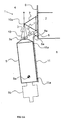
- Figs. 1-3 show a preferred embodiment of a subsea equipment motion restraining and guidance system mounted on a vessel according to the invention. Same parts are indicated with same numbers.
- a small part of a vessel 1 is shown. Part of a hull 2 is visible, as well as a part of a hoist cable 3 for lowering and retrieving subsea equipment 5.
- This hoist cable 3 is part of a subsea equipment hoist system further comprising a winch (not shown) for lowering and retrieving subsea equipment in a hoist area generally indicated with number 4.
- the hoist area 4 can be a moonpool located in the middle of the ship, but can also be located at the side or at the stern of the ship.
- the hoist cable 3 has a connector 3a for connecting to the subsea equipment 5 at a single pivotable connection point.
- Subsea equipment 5 can be any equipment used in the offshore oil and gas industry.
- the equipment can be well intervention equipment comprising tooling for bore holes, or production equipment to be placed on the seafloor.
- the equipment could also be e.g. an ROV, stack, template, a christmas tree etc.
- a rail assembly is used to which another subsea equipment is connected, e.g. to the lower end of the rail assembly.
- connecting means 5b are shown at the lower end of subsea equipment 5, capable of connecting the subsea equipment 5 to any desired subsea part.
- the rail assembly preferably has one or more rails engagable with the auxiliary trolley by the rail engaging members.
- the vessel further comprises a subsea equipment motion restraining and guidance system for restraining subsea equipment 5 motion relative to the vessel 1 in the hoist area 4 as the subsea equipment 5 is lowered into the sea and retrieved from the sea 6.
- the subsea equipment motion restraining and guidance system includes a main trolley 7 and an auxiliary trolley 8. Further the system comprises a vertical trolley guide structure 9 mounted on the hull 2 of the vessel 1 that allows for vertical travel of the main trolley 7 and the auxiliary trolley 8, wherein at least said auxiliary trolley can be lowered to a submerged position.
- main trolley 7 is composed of a rigid triangular bar construction of which two corners are connected to the trolley guide structure 9 and the other corner to a top end engagement member 10.
- the subsea equipment motion restraining and guidance system further comprises a top end engagement member 10, which is movably supported by said main trolley 7 and which is adapted to engage on a top end of the subsea equipment 5.
- Hoist cable 3 can pass through this top end engagement member 10, and through the main trolley 7 to which this top end engagement member 10 is connected.
- a guide member 10a is provided through which hoist cable 3 passes.
- top end engagement member 10 has a pendulum support pivotably connected to main trolley 7 allowing pivotal motion in all directions with respect to the main trolley 7.
- the top end engagement member 10 is provided with locking means 10b to lock the top end of the subsea equipment 5, once it is engaged in an engaging ring 10d of the top end engagement member 10.
- the locking means 10b can prevent rotation of the subsea equipment 5 in the top end engaging means, and, more important, allow for a firm connection between the subsea equipment 5 and the top end engagement member 10.
- the locking means 10b can for example be hydraulically operable locking means.
- top end engagement member 10 is provided with a drive mechanism 10c for rotating the engaged subsea equipment 5 about a vertical rotation axis in order to align the subsea equipment 5 with the auxiliary trolley 8, more in particular to align a vertical rail 11 with rail engagement members 8a (see below).
- Drive mechanism 10c can for example be a motor, preferably a hydraulically operable motor. This drive mechanism 10c can also act as a locking mechanism.
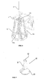
- Fig. 4 shows the top engagement member 10 and the main trolley 7 in detail.
- Damper means 12 are provided between the top end engagement member 10 and the main trolley 7, that allow for dampen motion of said top end engagement member 10.
- damper means 12 dampen the motion of the subsea equipment 5 relatively to the vessel.
- damper means 12 comprise hydraulic jacks, but any other damping means such as a spring or any pneumatics are also possible.
- only one hydraulic jack 12 is shown.
- two hydraulic jacks are mounted between the top end engagement member 10 and the main trolley 7.
- the hydraulic jacks can be placed in the shape of a horizontally orientated 'V', of which the top end is connected to the main trolley 7 and the ends to two spaced apart connecting points at the top end engagement member 10.
- the hydraulic jacks are connected to an associated hydraulic circuit (not shown) having a dampened motion mode, wherein the hydraulic jack piston is free to change length while the motion is dampened and a locking mode, wherein piston motion is blocked. This occurs e.g. by throttling the displacement of hydraulic fluid between the chambers of the hydraulic jack (not shown).
- the hydraulic circuit is also connected to hydraulic drive and locking means 10c of the top end engagement member 10 and can thereby also operate driving means 10c.
- damper means 12 act as locking means the position of said top end engagement member 10 is locked.
- the top end engagement member 10 is no longer movably supported by said main trolley 7, thereby preventing any collision between the subsea equipment 5 and the hull 2 of the vessel 1.
- the system further comprises two spaced apart parallel rail engaging members 8a, one of which is visible in fig. 1 , mounted on said auxiliary trolley 8.
- Each of the rail engaging members 8a is adapted to engage on one of two equally spaced parallel vertical rails 11 mounted on said subsea equipment 5 as said subsea equipment 5 passes vertically by said auxiliary trolley 8.
- Rails 11 could be any rail type, square or round, also including recesses, cables etc.
- a preferred embodiment of a rail engaging member 80 is shown.
- Rail engagement member 80 is shaped as a slotted annular member having a slot 81 allowing the passage of connecting members 11a arranged between the vertical rail and the subsea equipment 5 and a hollow 82 for receiving the rail.
- the engaging member 80 has a funnel 83 at the lower end thereof to simplify receiving the rail 11.
- these rail engaging members 8a are movably mounted on the auxiliary trolley 8, and more preferably they are pivotably mounted.
- Arresting means (not shown) are provided that allow for arresting the auxiliary trolley 8 in a submerged position thereof to the vertical trolley guide structure 9.
- the rail engaging members 8a By allowing the rail engaging members 8a to pivot, it is possible that one of the rail engaging members 8a engages on a vertical rail 11 first, followed by the engagement of the second vertical rail 11 by the second rail engaging member 8a. Additionally, pivotably mounted rail engaging members 8a enable the subsea equipment 5 to move in a controlled manner. When subsea equipment 5 is connected to the top end engagement member 10 dampened motion is allowed by damping means 12. By connecting the subsea equipment 5 to the auxiliary trolley 8 by two pivotable rail engaging members 8a, the motion of the subsea equipment 5 is restricted. Preferably, it can pivot about a first axis between the two rail engaging members 8a.
- the subsea equipment 5 can additionally tilt about a second horizontal axis between the rail engaging members 8a perpendicular to the first axis.
- the rail engaging members 8a can pivot about a vertical axis, it is possible to allow in a particular embodiment a limited rotation of the subsea equipment 5. This rotation is limited in that the rail engagement members 8a keep connected to rails 11 on the subsea equipment 5.
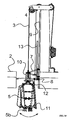
- Figs. 1a - 1d and 2a-2f show the operation of the vessel comprising a subsea equipment according to the invention.
- the subsea equipment 5 is retrieved from the sea 6 by hoist cable 3 in hoist area 4.. From fig. 2a it is clear that the subsea equipment is free to move over a large angle. To avoid interference with the hoist wire 3, the main trolley 7 and the auxiliary trolley 8 are in the highest possible position. In fig. 2b the subsea equipment 5 is raised to just below the bottom of the hull 2 of the ship. The main trolley 7 and the auxiliary trolley are lowered. By lowering the trolleys, the freedom of movement of the subsea equipment 5 is restricted noticeably. It can be discerned that the main trolley 7 and the auxiliary trolley 8 are connected to each other by a connecting bar 13, which is moveable in the vertical direction.
- Hydraulic jacks 12 allow for a dampened motion of the subea equipment 5.
- Drive mechanism 10c rotates the engaged subsea equipment 5 about a vertical rotation axis in order to align the subsea equipment 5 with the auxiliary trolley 8, more in particular to align the vertical rail 11 with rail engagement members 8a.
- the subsea equipment 5 is fixed in two dimensions by the main trolley 7 and auxiliary trolley 8..
- the top end engagement member 10 can be locked with respect to the main trolley 7. Only movement in the third, vertical direction is possible by the hoist cable 3. By unlocking the arrested auxiliary trolley 8, the auxiliary trolley can move upwards together with the subsea equipment 5..
Landscapes
- Engineering & Computer Science (AREA)
- Mechanical Engineering (AREA)
- Chemical & Material Sciences (AREA)
- Ocean & Marine Engineering (AREA)
- Life Sciences & Earth Sciences (AREA)
- Combustion & Propulsion (AREA)
- Geology (AREA)
- Mining & Mineral Resources (AREA)
- Environmental & Geological Engineering (AREA)
- Geochemistry & Mineralogy (AREA)
- General Life Sciences & Earth Sciences (AREA)
- Fluid Mechanics (AREA)
- Physics & Mathematics (AREA)
- Ship Loading And Unloading (AREA)
- Catching Or Destruction (AREA)
- Diaphragms For Electromechanical Transducers (AREA)
Claims (16)
- Behälter (1), vorzugsweise ein einschaliger Behälter, zum Handhaben einer Unterwasserausrüstung, insbesondere zur Verwendung in der Offshore-Industrie, wobei der Behälter umfasst:- eine Schale (2),- ein Unterwasserausrüstungs-Hebesystem mit einer Winde und einem Hebeseil (3) zum Versenken und Zurückholen einer Unterwasserausrüstung (5) in einem Hebebereich (4) des Behälters, und- ein Unterwasserausrüstung-Bewegungsbeschränkungs- und Führungssystem zum Beschränken einer Unterwasserausrüstungsbewegung relativ zum Behälter im Hebebereich, wenn die Unterwasserausrüstung im Wasser (6) versenkt und aus dem Wasser (6) zurückgeholt wird,wobei das System umfasst:- eine Haupt-Laufrolle (7),- eine Zusatz-Laufrolle (8),- einen auf die Schale (2) des Behälters montierten vertikalen Laufrollen-Führungsrahmen (9), der eine vertikale Bewegung der Haupt-Laufrolle und der Zusatz-Laufrolle erlaubt,dadurch gekennzeichnet, dass
das Unterwasserausrüstung-Bewegungsbeschränkungs- und Führungssystem ferner umfasst:- ein Oberseiten-Angreifelement (10), welches durch die Haupt-Laufrolle beweglich abgestützt ist und welches so ausgebildet ist, dass dieses an ein oberseitiges Ende der Unterwasserausrüstung angreifen kann,- ein oder mehrere Schienen-Angreifelemente (8a), die auf der Zusatz-Laufrolle (8) montiert sind, wobei jedes so ausgebildet ist, dass dieses an eine vertikale Schiene (11) angreifen kann, die auf der Unterwasserausrüstung (5) montiert ist, wenn sich die Unterwasserausrüstung an der Zusatz-Laufrolle (8) vertikal vorbeibewegt. - Behälter nach Anspruch 1, in welchem das Hebeseil (3) einen Verbinder (3a) zum Verbinden der Unterwasserausrüstung an einem einzigen schwenkbaren Verbindungspunkt aufweist.
- Behälter nach Anspruch 1 oder 2, in welchem das Unterwasserausrüstung-Bewegungsbeschränkungs- und Führungssystem ferner eine Arretierungseinrichtung umfasst, die ein Arretieren der Zusatz-Laufrolle in ihrer eingetauchten Position erlaubt.
- Behälter nach einem der vorhergehenden Ansprüche, in welchem das Oberseiten-Angreifelement (10) eine Pendelstütze aufweist, welche eine schwenkbare Bewegung in allen Richtungen in Bezug auf die Haupt-Laufrolle (7) erlaubt.
- Behälter nach einem der vorhergehenden Ansprüche, in welchem eine Dämpfereinrichtung (12) zwischen dem Oberseiten-Angreifelement (10) und der Haupt-Laufrolle (7) vorgesehen ist, welche ein Dämpfen der Bewegung des Oberseiten-Angreifelements (10) und einer damit verbundenen Unterwasserausrüstung (5) erlaubt.
- Behälter nach einem der vorhergehenden Ansprüche, in welchem eine Blockiereinrichtung (10) zwischen dem Oberseiten-Angreifelement und der Haupt-Laufrolle vorgesehen ist, welche ein Blockieren der Position des Oberseiten-Angreifelements erlaubt.
- Behälter nach einem der vorhergehenden Ansprüche, in welchem ein oder mehrere hydraulische Heber (12) zwischen dem Oberseiten-Angreifelement (10) und der Haupt-Laufrolle (7) angeordnet sind.
- Behälter nach Anspruch 7, in welchem die ein oder mehreren hydraulischen Heber mit einem zugehörigen hydraulischen Kreislauf verbunden sind, die aufweisen einen Dämpfbewegungsmodus, wobei ein hydraulischer Heber seine Länge bei gleichzeitig gedämpfter Bewegung verändern kann (z. B. durch Drosselung der Verschiebung eines hydraulischen Fluids zwischen den Kammern des hydraulischen Hebers), und einen Blockiermodus, in welchem die Kolbenbewegung blockiert ist.
- Behälter nach einem der vorhergehenden Ansprüche, in welchem die ein oder mehreren Schienen-Angreifeinrichtungen (8a) auf der Zusatz-Laufrolle (8) beweglich montiert sind.
- Behälter nach einem der vorhergehenden Ansprüche, wobei ein oder mehrere Schienen-Angreifeinrichtungen schwenkbar montiert sind, vorzugsweise um eine horizontale Schwenkachse.
- Behälter nach einem der vorhergehenden Ansprüche, in welchem eine Schienen-Angreifeinrichtung (8a) ein ringförmiges Element ist, in welchem die Schiene gleitet, wenn die Unterwasserausrüstung versenkt oder zurückgeholt wird, vorzugsweise ein Zylinder mit einem Trichter (83) an seinem unteren Ende.
- Behälter nach einem der vorhergehenden Ansprüche, in welchem eine Schienen-Angreifeinrichtung (80) ein geschlitztes ringförmiges Element ist, das einen Schlitz (81) aufweist, welcher den Durchgang eines Verbindungselements (11a) erlaubt, das zwischen der vertikalen Schiene und der Unterwasserausrüstung (5) angeordnet ist.
- Behälter nach einem der vorhergehenden Ansprüche, in welchem zwei in Abstand zueinander liegende, parallele Schienen-Angreifelemente (8a) auf der Zusatz-Laufrolle (8) montiert sind, wobei jedes eine von zwei in gleichem Abstand liegende, parallele Schienen (11) aufnehmen kann, die auf der Unterwasserausrüstung (5) montiert sind.
- Behälter nach einem der vorhergehenden Ansprüche, in welchem die Haupt-Laufrolle Führungselemente (10a) umfasst, durch welche das Hebeseil (3) hindurch läuft.
- Behälter nach einem der vorhergehenden Ansprüche, in welchem die Oberseiten-Angreifeinrichtung (10) mit einem Antriebsmechanismus (10c) versehen ist, um die angegriffene Unterwasserausrüstung (5) um eine vertikale Drehachse zu drehen, damit die vertikale Schiene mit den Schienen-Angreifelementen (8a) ausgerichtet werden kann.
- Verfahren zum Versenken und Zurückholen einer Unterwasserausrüstung, in welchem ein Behälter nach einem der vorhergehenden Ansprüche 1 - 15 verwendet wird.
Applications Claiming Priority (1)
| Application Number | Priority Date | Filing Date | Title |
|---|---|---|---|
| PCT/NL2005/000623 WO2007027081A1 (en) | 2005-08-29 | 2005-08-29 | Vessel comprising a subsea equipment motion restraining and guidance system |
Publications (2)
| Publication Number | Publication Date |
|---|---|
| EP1931561A1 EP1931561A1 (de) | 2008-06-18 |
| EP1931561B1 true EP1931561B1 (de) | 2010-06-16 |
Family
ID=36215566
Family Applications (1)
| Application Number | Title | Priority Date | Filing Date |
|---|---|---|---|
| EP05775143A Expired - Lifetime EP1931561B1 (de) | 2005-08-29 | 2005-08-29 | Schiff mit einem system zum festhalten und führen von unterwasserausrüstung |
Country Status (6)
| Country | Link |
|---|---|
| US (1) | US8056492B2 (de) |
| EP (1) | EP1931561B1 (de) |
| AT (1) | ATE471275T1 (de) |
| BR (1) | BRPI0520496A2 (de) |
| DE (1) | DE602005021925D1 (de) |
| WO (1) | WO2007027081A1 (de) |
Families Citing this family (14)
| Publication number | Priority date | Publication date | Assignee | Title |
|---|---|---|---|---|
| GB2466992A (en) * | 2009-01-20 | 2010-07-21 | Subsea Engineering Services Lt | Tool for alignment of subsea equipment during deployment and recovery. |
| BR112013007844A2 (pt) * | 2010-10-01 | 2016-06-07 | Aker Subsea Inc | sistema de tubo ascendente para unidade flutuante de casco amarrado com folga |
| NL2006667C2 (en) | 2011-04-26 | 2012-10-29 | Ihc Holland Ie Bv | Vessel comprising a moon pool and a hoisting arrangement and method of lowering items into the sea. |
| JP5759246B2 (ja) * | 2011-04-27 | 2015-08-05 | 三井造船株式会社 | 水中航走体の着水揚収方法および水中航走体の着水揚収に用いる保持金具 |
| NO336080B1 (no) * | 2011-11-18 | 2015-05-04 | Giertsen As W | Fartøy og fremgangsmåte for undervannsslep av tunge laster |
| US8903108B2 (en) * | 2011-12-06 | 2014-12-02 | Apple Inc. | Near-field null and beamforming |
| GB201209131D0 (en) | 2012-05-24 | 2012-07-04 | Subsea 7 Contracting Norway As | Handling loads in offshore environments |
| CN103693159A (zh) * | 2013-09-17 | 2014-04-02 | 南通中远船务工程有限公司 | 船舶海底阀箱导向装置 |
| US9140091B1 (en) * | 2013-10-30 | 2015-09-22 | Trendsetter Engineering, Inc. | Apparatus and method for adjusting an angular orientation of a subsea structure |
| NL2012527B1 (en) * | 2014-03-28 | 2016-02-10 | Bluemarine Offshore Yard Service Bv | Method for lowering a subsea structure having a substantially flat support base into the water through the splash zone. |
| MY190840A (en) * | 2015-04-10 | 2022-05-12 | Keppel Offshore & Marine Tech Ct Pte Ltd | A vessel having a retractable cursor frame assembly |
| SG11201811832QA (en) * | 2016-07-07 | 2019-01-30 | Ensco Int Inc | Lift frame storage and deployment |
| FR3057242B1 (fr) * | 2016-10-11 | 2020-01-24 | Stx France S.A. | Navire pourvu d'une installation de mise a l'eau et de recuperation d'engins |
| GB2576333C (en) * | 2018-08-14 | 2024-05-08 | Subsea 7 Do Brasil Servicos Ltda | Handling loads in subsea operations |
Family Cites Families (6)
| Publication number | Priority date | Publication date | Assignee | Title |
|---|---|---|---|---|
| US2874855A (en) * | 1957-07-02 | 1959-02-24 | Texas Co | Personnel or object transfer apparatus and method |
| FR2401867A1 (fr) * | 1977-09-02 | 1979-03-30 | Expertises Sa Cie Maritime | Procede et dispositif de manutention d'un engin sous-marin |
| NO973972L (no) * | 1997-08-29 | 1999-03-01 | Dsnd Offshore As | Anordning ved en flyttbar installasjon, sµrlig et offshorefart°y |
| EP1103459A1 (de) | 1999-11-24 | 2001-05-30 | Mercur Slimhole Drilling and Intervention AS | Anordnung zum Ausgleich von Tauch- und Tidebewegungen |
| US6871609B2 (en) * | 2002-08-30 | 2005-03-29 | Itrec B.V. | Multipurpose tower for monohull |
| US20050147473A1 (en) * | 2004-01-07 | 2005-07-07 | Vetco Gray Inc. | Riser tensioner with shrouded rods |
-
2005
- 2005-08-29 EP EP05775143A patent/EP1931561B1/de not_active Expired - Lifetime
- 2005-08-29 DE DE602005021925T patent/DE602005021925D1/de not_active Expired - Lifetime
- 2005-08-29 US US11/991,140 patent/US8056492B2/en active Active
- 2005-08-29 WO PCT/NL2005/000623 patent/WO2007027081A1/en not_active Ceased
- 2005-08-29 BR BRPI0520496-8A patent/BRPI0520496A2/pt not_active Application Discontinuation
- 2005-08-29 AT AT05775143T patent/ATE471275T1/de not_active IP Right Cessation
Also Published As
| Publication number | Publication date |
|---|---|
| BRPI0520496A2 (pt) | 2009-09-29 |
| WO2007027081A1 (en) | 2007-03-08 |
| US8056492B2 (en) | 2011-11-15 |
| US20090199757A1 (en) | 2009-08-13 |
| DE602005021925D1 (de) | 2010-07-29 |
| ATE471275T1 (de) | 2010-07-15 |
| EP1931561A1 (de) | 2008-06-18 |
Similar Documents
| Publication | Publication Date | Title |
|---|---|---|
| EP1931561B1 (de) | Schiff mit einem system zum festhalten und führen von unterwasserausrüstung | |
| JP7524424B2 (ja) | 調整可能な杭保持システム、船舶および杭設置方法 | |
| US4616707A (en) | Riser braking clamp apparatus | |
| KR102051366B1 (ko) | 크레인선 | |
| US7083004B2 (en) | Cantilevered multi purpose tower and method for installing drilling equipment | |
| US7156040B2 (en) | Extended semi-submersible vessel (ESEMI) | |
| US6729804B1 (en) | Cantilevered tower for jack-up platform | |
| US8522880B2 (en) | Floating offshore structure for hydrocarbon production | |
| KR102400054B1 (ko) | 스프레드 무어링 설비 및 이를 포함하는 해양 부유 구조물 | |
| WO2016114820A1 (en) | Floating deep draft semi-submersible offshore platforms and methods for assembling and deploying same | |
| WO2022229455A1 (en) | Upend crane and installation vessel | |
| AU2015330696B2 (en) | Floating platform with an articulating keel skirt | |
| CN101253093B (zh) | 包括海底设备运动限制和导向系统的船 | |
| AU751793B2 (en) | Umbilical constraint mechanism | |
| US9604704B2 (en) | Dual axis chain stopper | |
| EP3411290B1 (de) | Verankerungsverbinderanordnung | |
| EP3243734B1 (de) | Anlage von einem wasserfahrzeug und einem schwimmenden module | |
| CN113784887B (zh) | 用于执行海底钻井孔相关活动的海上系统、船和方法 | |
| US20190177133A1 (en) | Offshore system with movable cantilever | |
| US20090211999A1 (en) | Underwater deployment system | |
| KR20130104324A (ko) | 시추선의 스러스터 유지보수방법 | |
| KR101556268B1 (ko) | 캐니스터식 스러스터 설치방법 | |
| KR20170110414A (ko) | 해양플랜트용 스러스터 리커버리의 상승운전 제어장치 | |
| KR101973083B1 (ko) | 해양구조물 | |
| KR101599450B1 (ko) | 터렛의 토크증가장치 및 무어링테이블 유닛 |
Legal Events
| Date | Code | Title | Description |
|---|---|---|---|
| PUAI | Public reference made under article 153(3) epc to a published international application that has entered the european phase |
Free format text: ORIGINAL CODE: 0009012 |
|
| 17P | Request for examination filed |
Effective date: 20080320 |
|
| AK | Designated contracting states |
Kind code of ref document: A1 Designated state(s): AT BE BG CH CY CZ DE DK EE ES FI FR GB GR HU IE IS IT LI LT LU LV MC NL PL PT RO SE SI SK TR |
|
| 17Q | First examination report despatched |
Effective date: 20081020 |
|
| GRAP | Despatch of communication of intention to grant a patent |
Free format text: ORIGINAL CODE: EPIDOSNIGR1 |
|
| GRAS | Grant fee paid |
Free format text: ORIGINAL CODE: EPIDOSNIGR3 |
|
| GRAA | (expected) grant |
Free format text: ORIGINAL CODE: 0009210 |
|
| AK | Designated contracting states |
Kind code of ref document: B1 Designated state(s): AT BE BG CH CY CZ DE DK EE ES FI FR GB GR HU IE IS IT LI LT LU LV MC NL PL PT RO SE SI SK TR |
|
| REG | Reference to a national code |
Ref country code: CH Ref legal event code: EP |
|
| REG | Reference to a national code |
Ref country code: IE Ref legal event code: FG4D |
|
| REF | Corresponds to: |
Ref document number: 602005021925 Country of ref document: DE Date of ref document: 20100729 Kind code of ref document: P |
|
| REG | Reference to a national code |
Ref country code: NL Ref legal event code: T3 |
|
| PG25 | Lapsed in a contracting state [announced via postgrant information from national office to epo] |
Ref country code: SE Free format text: LAPSE BECAUSE OF FAILURE TO SUBMIT A TRANSLATION OF THE DESCRIPTION OR TO PAY THE FEE WITHIN THE PRESCRIBED TIME-LIMIT Effective date: 20100616 Ref country code: LT Free format text: LAPSE BECAUSE OF FAILURE TO SUBMIT A TRANSLATION OF THE DESCRIPTION OR TO PAY THE FEE WITHIN THE PRESCRIBED TIME-LIMIT Effective date: 20100616 |
|
| LTIE | Lt: invalidation of european patent or patent extension |
Effective date: 20100616 |
|
| PG25 | Lapsed in a contracting state [announced via postgrant information from national office to epo] |
Ref country code: SI Free format text: LAPSE BECAUSE OF FAILURE TO SUBMIT A TRANSLATION OF THE DESCRIPTION OR TO PAY THE FEE WITHIN THE PRESCRIBED TIME-LIMIT Effective date: 20100616 Ref country code: LV Free format text: LAPSE BECAUSE OF FAILURE TO SUBMIT A TRANSLATION OF THE DESCRIPTION OR TO PAY THE FEE WITHIN THE PRESCRIBED TIME-LIMIT Effective date: 20100616 Ref country code: FI Free format text: LAPSE BECAUSE OF FAILURE TO SUBMIT A TRANSLATION OF THE DESCRIPTION OR TO PAY THE FEE WITHIN THE PRESCRIBED TIME-LIMIT Effective date: 20100616 Ref country code: AT Free format text: LAPSE BECAUSE OF FAILURE TO SUBMIT A TRANSLATION OF THE DESCRIPTION OR TO PAY THE FEE WITHIN THE PRESCRIBED TIME-LIMIT Effective date: 20100616 |
|
| PG25 | Lapsed in a contracting state [announced via postgrant information from national office to epo] |
Ref country code: PL Free format text: LAPSE BECAUSE OF FAILURE TO SUBMIT A TRANSLATION OF THE DESCRIPTION OR TO PAY THE FEE WITHIN THE PRESCRIBED TIME-LIMIT Effective date: 20100616 Ref country code: GR Free format text: LAPSE BECAUSE OF FAILURE TO SUBMIT A TRANSLATION OF THE DESCRIPTION OR TO PAY THE FEE WITHIN THE PRESCRIBED TIME-LIMIT Effective date: 20100917 Ref country code: CY Free format text: LAPSE BECAUSE OF FAILURE TO SUBMIT A TRANSLATION OF THE DESCRIPTION OR TO PAY THE FEE WITHIN THE PRESCRIBED TIME-LIMIT Effective date: 20100616 |
|
| PG25 | Lapsed in a contracting state [announced via postgrant information from national office to epo] |
Ref country code: EE Free format text: LAPSE BECAUSE OF FAILURE TO SUBMIT A TRANSLATION OF THE DESCRIPTION OR TO PAY THE FEE WITHIN THE PRESCRIBED TIME-LIMIT Effective date: 20100616 |
|
| PG25 | Lapsed in a contracting state [announced via postgrant information from national office to epo] |
Ref country code: SK Free format text: LAPSE BECAUSE OF FAILURE TO SUBMIT A TRANSLATION OF THE DESCRIPTION OR TO PAY THE FEE WITHIN THE PRESCRIBED TIME-LIMIT Effective date: 20100616 Ref country code: RO Free format text: LAPSE BECAUSE OF FAILURE TO SUBMIT A TRANSLATION OF THE DESCRIPTION OR TO PAY THE FEE WITHIN THE PRESCRIBED TIME-LIMIT Effective date: 20100616 Ref country code: PT Free format text: LAPSE BECAUSE OF FAILURE TO SUBMIT A TRANSLATION OF THE DESCRIPTION OR TO PAY THE FEE WITHIN THE PRESCRIBED TIME-LIMIT Effective date: 20101018 Ref country code: IS Free format text: LAPSE BECAUSE OF FAILURE TO SUBMIT A TRANSLATION OF THE DESCRIPTION OR TO PAY THE FEE WITHIN THE PRESCRIBED TIME-LIMIT Effective date: 20101016 Ref country code: CZ Free format text: LAPSE BECAUSE OF FAILURE TO SUBMIT A TRANSLATION OF THE DESCRIPTION OR TO PAY THE FEE WITHIN THE PRESCRIBED TIME-LIMIT Effective date: 20100616 Ref country code: BE Free format text: LAPSE BECAUSE OF FAILURE TO SUBMIT A TRANSLATION OF THE DESCRIPTION OR TO PAY THE FEE WITHIN THE PRESCRIBED TIME-LIMIT Effective date: 20100616 |
|
| PG25 | Lapsed in a contracting state [announced via postgrant information from national office to epo] |
Ref country code: IT Free format text: LAPSE BECAUSE OF FAILURE TO SUBMIT A TRANSLATION OF THE DESCRIPTION OR TO PAY THE FEE WITHIN THE PRESCRIBED TIME-LIMIT Effective date: 20100616 Ref country code: MC Free format text: LAPSE BECAUSE OF NON-PAYMENT OF DUE FEES Effective date: 20100831 |
|
| REG | Reference to a national code |
Ref country code: CH Ref legal event code: PL |
|
| PLBE | No opposition filed within time limit |
Free format text: ORIGINAL CODE: 0009261 |
|
| STAA | Information on the status of an ep patent application or granted ep patent |
Free format text: STATUS: NO OPPOSITION FILED WITHIN TIME LIMIT |
|
| PG25 | Lapsed in a contracting state [announced via postgrant information from national office to epo] |
Ref country code: CH Free format text: LAPSE BECAUSE OF NON-PAYMENT OF DUE FEES Effective date: 20100831 Ref country code: DK Free format text: LAPSE BECAUSE OF FAILURE TO SUBMIT A TRANSLATION OF THE DESCRIPTION OR TO PAY THE FEE WITHIN THE PRESCRIBED TIME-LIMIT Effective date: 20100616 Ref country code: LI Free format text: LAPSE BECAUSE OF NON-PAYMENT OF DUE FEES Effective date: 20100831 |
|
| REG | Reference to a national code |
Ref country code: FR Ref legal event code: ST Effective date: 20110502 |
|
| 26N | No opposition filed |
Effective date: 20110317 |
|
| REG | Reference to a national code |
Ref country code: DE Ref legal event code: R119 Ref document number: 602005021925 Country of ref document: DE Effective date: 20110301 |
|
| PG25 | Lapsed in a contracting state [announced via postgrant information from national office to epo] |
Ref country code: FR Free format text: LAPSE BECAUSE OF NON-PAYMENT OF DUE FEES Effective date: 20100831 Ref country code: DE Free format text: LAPSE BECAUSE OF NON-PAYMENT OF DUE FEES Effective date: 20110301 Ref country code: IE Free format text: LAPSE BECAUSE OF NON-PAYMENT OF DUE FEES Effective date: 20100829 |
|
| PG25 | Lapsed in a contracting state [announced via postgrant information from national office to epo] |
Ref country code: LU Free format text: LAPSE BECAUSE OF NON-PAYMENT OF DUE FEES Effective date: 20100829 Ref country code: HU Free format text: LAPSE BECAUSE OF FAILURE TO SUBMIT A TRANSLATION OF THE DESCRIPTION OR TO PAY THE FEE WITHIN THE PRESCRIBED TIME-LIMIT Effective date: 20101217 Ref country code: BG Free format text: LAPSE BECAUSE OF FAILURE TO SUBMIT A TRANSLATION OF THE DESCRIPTION OR TO PAY THE FEE WITHIN THE PRESCRIBED TIME-LIMIT Effective date: 20100616 |
|
| PG25 | Lapsed in a contracting state [announced via postgrant information from national office to epo] |
Ref country code: TR Free format text: LAPSE BECAUSE OF FAILURE TO SUBMIT A TRANSLATION OF THE DESCRIPTION OR TO PAY THE FEE WITHIN THE PRESCRIBED TIME-LIMIT Effective date: 20100616 |
|
| PG25 | Lapsed in a contracting state [announced via postgrant information from national office to epo] |
Ref country code: BG Free format text: LAPSE BECAUSE OF FAILURE TO SUBMIT A TRANSLATION OF THE DESCRIPTION OR TO PAY THE FEE WITHIN THE PRESCRIBED TIME-LIMIT Effective date: 20100916 |
|
| PG25 | Lapsed in a contracting state [announced via postgrant information from national office to epo] |
Ref country code: ES Free format text: LAPSE BECAUSE OF FAILURE TO SUBMIT A TRANSLATION OF THE DESCRIPTION OR TO PAY THE FEE WITHIN THE PRESCRIBED TIME-LIMIT Effective date: 20100927 |
|
| PGFP | Annual fee paid to national office [announced via postgrant information from national office to epo] |
Ref country code: NL Payment date: 20230825 Year of fee payment: 19 |
|
| PGFP | Annual fee paid to national office [announced via postgrant information from national office to epo] |
Ref country code: GB Payment date: 20230824 Year of fee payment: 19 |
|
| REG | Reference to a national code |
Ref country code: NL Ref legal event code: MM Effective date: 20240901 |
|
| GBPC | Gb: european patent ceased through non-payment of renewal fee |
Effective date: 20240829 |
|
| PG25 | Lapsed in a contracting state [announced via postgrant information from national office to epo] |
Ref country code: NL Free format text: LAPSE BECAUSE OF NON-PAYMENT OF DUE FEES Effective date: 20240901 |
|
| PG25 | Lapsed in a contracting state [announced via postgrant information from national office to epo] |
Ref country code: GB Free format text: LAPSE BECAUSE OF NON-PAYMENT OF DUE FEES Effective date: 20240829 |