EP1931879B1 - Flügelzellenpumpe - Google Patents
Flügelzellenpumpe Download PDFInfo
- Publication number
- EP1931879B1 EP1931879B1 EP06792220A EP06792220A EP1931879B1 EP 1931879 B1 EP1931879 B1 EP 1931879B1 EP 06792220 A EP06792220 A EP 06792220A EP 06792220 A EP06792220 A EP 06792220A EP 1931879 B1 EP1931879 B1 EP 1931879B1
- Authority
- EP
- European Patent Office
- Prior art keywords
- guide ring
- front side
- cell pump
- vane cell
- pump according
- Prior art date
- Legal status (The legal status is an assumption and is not a legal conclusion. Google has not performed a legal analysis and makes no representation as to the accuracy of the status listed.)
- Not-in-force
Links
- 230000002093 peripheral effect Effects 0.000 description 8
- 239000012530 fluid Substances 0.000 description 2
- 238000003754 machining Methods 0.000 description 2
- 238000004519 manufacturing process Methods 0.000 description 1
Images

Classifications
-
- F—MECHANICAL ENGINEERING; LIGHTING; HEATING; WEAPONS; BLASTING
- F04—POSITIVE - DISPLACEMENT MACHINES FOR LIQUIDS; PUMPS FOR LIQUIDS OR ELASTIC FLUIDS
- F04C—ROTARY-PISTON, OR OSCILLATING-PISTON, POSITIVE-DISPLACEMENT MACHINES FOR LIQUIDS; ROTARY-PISTON, OR OSCILLATING-PISTON, POSITIVE-DISPLACEMENT PUMPS
- F04C2/00—Rotary-piston machines or pumps
- F04C2/30—Rotary-piston machines or pumps having the characteristics covered by two or more groups F04C2/02, F04C2/08, F04C2/22, F04C2/24 or having the characteristics covered by one of these groups together with some other type of movement between co-operating members
- F04C2/34—Rotary-piston machines or pumps having the characteristics covered by two or more groups F04C2/02, F04C2/08, F04C2/22, F04C2/24 or having the characteristics covered by one of these groups together with some other type of movement between co-operating members having the movement defined in groups F04C2/08 or F04C2/22 and relative reciprocation between the co-operating members
- F04C2/344—Rotary-piston machines or pumps having the characteristics covered by two or more groups F04C2/02, F04C2/08, F04C2/22, F04C2/24 or having the characteristics covered by one of these groups together with some other type of movement between co-operating members having the movement defined in groups F04C2/08 or F04C2/22 and relative reciprocation between the co-operating members with vanes reciprocating with respect to the inner member
- F04C2/3441—Rotary-piston machines or pumps having the characteristics covered by two or more groups F04C2/02, F04C2/08, F04C2/22, F04C2/24 or having the characteristics covered by one of these groups together with some other type of movement between co-operating members having the movement defined in groups F04C2/08 or F04C2/22 and relative reciprocation between the co-operating members with vanes reciprocating with respect to the inner member the inner and outer member being in contact along one line or continuous surface substantially parallel to the axis of rotation
- F04C2/3445—Rotary-piston machines or pumps having the characteristics covered by two or more groups F04C2/02, F04C2/08, F04C2/22, F04C2/24 or having the characteristics covered by one of these groups together with some other type of movement between co-operating members having the movement defined in groups F04C2/08 or F04C2/22 and relative reciprocation between the co-operating members with vanes reciprocating with respect to the inner member the inner and outer member being in contact along one line or continuous surface substantially parallel to the axis of rotation the vanes having the form of rollers, slippers or the like
-
- F—MECHANICAL ENGINEERING; LIGHTING; HEATING; WEAPONS; BLASTING
- F01—MACHINES OR ENGINES IN GENERAL; ENGINE PLANTS IN GENERAL; STEAM ENGINES
- F01C—ROTARY-PISTON OR OSCILLATING-PISTON MACHINES OR ENGINES
- F01C21/00—Component parts, details or accessories not provided for in groups F01C1/00 - F01C20/00
- F01C21/08—Rotary pistons
- F01C21/0809—Construction of vanes or vane holders
- F01C21/0818—Vane tracking; control therefor
- F01C21/0827—Vane tracking; control therefor by mechanical means
- F01C21/0836—Vane tracking; control therefor by mechanical means comprising guiding means, e.g. cams, rollers
-
- F—MECHANICAL ENGINEERING; LIGHTING; HEATING; WEAPONS; BLASTING
- F04—POSITIVE - DISPLACEMENT MACHINES FOR LIQUIDS; PUMPS FOR LIQUIDS OR ELASTIC FLUIDS
- F04C—ROTARY-PISTON, OR OSCILLATING-PISTON, POSITIVE-DISPLACEMENT MACHINES FOR LIQUIDS; ROTARY-PISTON, OR OSCILLATING-PISTON, POSITIVE-DISPLACEMENT PUMPS
- F04C18/00—Rotary-piston pumps specially adapted for elastic fluids
- F04C18/30—Rotary-piston pumps specially adapted for elastic fluids having the characteristics covered by two or more of groups F04C18/02, F04C18/08, F04C18/22, F04C18/24, F04C18/48, or having the characteristics covered by one of these groups together with some other type of movement between co-operating members
- F04C18/34—Rotary-piston pumps specially adapted for elastic fluids having the characteristics covered by two or more of groups F04C18/02, F04C18/08, F04C18/22, F04C18/24, F04C18/48, or having the characteristics covered by one of these groups together with some other type of movement between co-operating members having the movement defined in group F04C18/08 or F04C18/22 and relative reciprocation between the co-operating members
- F04C18/344—Rotary-piston pumps specially adapted for elastic fluids having the characteristics covered by two or more of groups F04C18/02, F04C18/08, F04C18/22, F04C18/24, F04C18/48, or having the characteristics covered by one of these groups together with some other type of movement between co-operating members having the movement defined in group F04C18/08 or F04C18/22 and relative reciprocation between the co-operating members with vanes reciprocating with respect to the inner member
Definitions
- the invention relates to a vane pump consisting of an outer rotor, an inner rotor and a plurality of vanes, which are mounted radially displaceably in substantially radial slots in the inner rotor and pivotally mounted on the outer rotor, wherein the outer rotor is formed by sliding shoes, wherein the sliding shoes on the inner peripheral surface slide along a stator and are guided with their axial end faces in a guideway.
- Such a wing cell pump is from the GB 319 467 known, which is considered as the nearest combative prior art.
- a vane pump with an annular inner rotor known, in which a plurality of radially outwardly extending wing elements are received radially displaceable.
- the radially inner end portions of the wing elements are supported on a non-rotatable central part, the radially outer end portions of a non-rotatable outer ring.
- the rotor can be rotated about a rotation axis that is offset from the central axis of the central part and the outer ring. In this way, at a rotational movement of the rotor between the wing elements initially larger and then again smaller conveyor cells or work spaces. Due to the change in volume of the delivery cells fluid is first sucked into the delivery cells and then ejected again. The end regions of the wing elements slide on the central part or the outer ring.
- Such a vane pump can be made simple and inexpensive.
- a vane pump in the form of a pendulum slide pump known.
- the wing elements are slidably received in an inner rotor, whereas they are in a annular outer rotor are pivotally supported.
- the axis of rotation of the inner rotor is offset with respect to the axis of rotation of the outer rotor, whereby in operation also initially magnifying and then shrinking conveyor cells are formed.
- known pendulum slide pump is complex and therefore expensive to manufacture.
- Object of the present invention is to provide a vane pump, which has a high efficiency and at the same time can be easily and inexpensively manufactured and assembled.
- the inventive design of the vane pump with a guideway having guide ring has the significant advantage that the vane pump is much simpler, since it consists on the one hand of fewer components, on the other hand, the components are designed simpler. Therefore, it is also much easier to install.
- the guide ring serves to guide the sliding shoes so that they are always, i. abut in any operating situation of the vane pump on the inner peripheral surface of the stator and even regardless of the speed of the vane pump.
- the guideway is therefore a forced guide for the sliding blocks, which ensures their permanent and fluid-tight contact with the inner circumferential surface.
- the design of the positive guide as a guide ring has the significant advantage that the working chambers of the vane pump are always axially accessible and are not closed by control or guide elements. To have to So no special breakthroughs are provided in components that would also hinder or interfere with the flow of the working fluid.
- the guide ring has a substantially C-shaped, ie laterally open cross-section with two free legs and a recess extending in the circumferential direction, in particular annular groove.
- Such a guide ring can be easily manufactured and is easy to install because it has no undercuts and because the ring is the same for both the front and the back, that is, the same for both faces of the pump.
- the stator and the sliding shoes can be recorded without play.
- the two free legs of the guide ring show axially inwards.
- the guide ring has a flat, forming the base of the ring outside, for example, rests on a closure cap.
- the two free legs of the guide ring surround the end face of the stator and thus define the position of the ring relative to the stator and thus within the vane pump. In this way, the stator is fixed in the pump.
- one of the two free limbs of the guide ring engages in an end recess of the sliding shoes.
- the frontal depression is a part-annular groove.
- the guide ring is mounted on the front side of the stator and the sliding shoes.
- This embodiment allows for easy assembly by only the guide ring must be axially attached to the axial end faces of the shoes.
- the sliding blocks can be held, for example by means of a special mounting tool in abutment against the inner peripheral surface of the stator until the guide ring is positioned.
- the cross-section of the end portion of the shoe is C-shaped, that is, laterally open, and the recess is flanked by two axially outwardly projecting legs.
- the guide ring and the shoes are therefore both C-shaped and engage with each other by interlocking, by the two sides facing the grooves are facing each other.
- the radially inner leg of the sliding shoe abuts the radial inner peripheral surface of the guide ring.
- an additional guidance is achieved, so that not only is it ensured that the sliding shoe does not lift off from the inner peripheral surface of the stator, but also that at high speeds, part of the contact pressure of the sliding shoe is absorbed by the guide ring.
- a particularly preferred embodiment provides that the axial end face of the radially inner leg of the sliding block and the axially outer end face of the guide ring lie in the same plane.
- the axially outer end face of the guide ring and the axial end faces of the wings in the same plane. This creates the possibility that each working space can be closed in a simple manner by a flat surface of a lid which bears against the two axial end faces of the sliding shoe and the guide ring.
- a fluid-tight system can be ensured by an end-side machining of the guide ring and the sliding blocks and the frontal surfaces of the wings.
- FIG. 1 shows a side view of a generally designated 10 vane pump having an inner rotor 12 which is driven by a drive shaft 14.
- the inner rotor 12 has radial slots 16, in each of which a wing 18 is slidably mounted in the radial direction.
- the wing 18 has a thickened outer end 20, on which a sliding shoe 22 is pivotally mounted.
- This shoe 22 is as out FIG. 3 can be seen on the inner peripheral surface 24 of a stator 26 at.
- These sliding shoes 22 form an outer rotor 28 which rotates together with the inner rotor 12 in the circumferential direction with respect to the stator 26.
- the wings 18, the inner rotor 12 and the sliding blocks 22 together with the stator 26 work spaces 30, which increase and decrease again when the inner rotor 12 rotates.
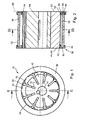
- FIG. 4 can be seen that on the end faces 32 and 34 of the stator 26 and the sliding blocks 22, a guide ring 36 is placed, which is described in more detail below.
- the guide ring points, as from the Figures 2 and 4 can be seen, a C-shaped cross-section, wherein the two legs 38 and 40 are aligned parallel to each other and facing axially inwards.
- the leg 38 surrounds the stator 26 at the edge on its radial outer side 42 and the inner leg 40 engages in a groove 44 formed as a recess 46 on the end face 34 of the shoe 22 a.
- This is clear in the Figures 2 and 4 recognizable.
- the sliding shoe 22 is held on the inner circumferential surface 24 of the stator 26.
- the guide ring 36 between its two legs 38 and 40, a guide groove 48, in which, as already mentioned, the edge of the end face 32 of the stator 36 and a radially outer leg 50 of the C-shaped end face 34 of the slide shoe 22 engages.
- the other leg 52 in which the free end of the wing 18 is pivotally mounted, abuts against the inner peripheral surface 54 of the guide ring 36.
- FIG. 2 It can also be seen that the end face 56 of the leg 52 of the sliding block 22 and the axially outer end face 58 of the guide ring 36 lie in a common plane 60. In this plane 60 also lies the axial end face 62 of each wing 18. Finally, in this plane 60 is still the axial end face 64 of the inner rotor 12. This creates a simple way to close the work spaces 30 by simply placing a flat lid. In addition, it is readily apparent that the vane pump 10 according to the invention can be easily assembled and is constructed from a few components.
Landscapes
- Engineering & Computer Science (AREA)
- Mechanical Engineering (AREA)
- General Engineering & Computer Science (AREA)
- Rotary Pumps (AREA)
- Details And Applications Of Rotary Liquid Pumps (AREA)
Description
- Die Erfindung betrifft eine Flügelzellenpumpe bestehend aus einem Außenrotor, einem Innenrotor und einer Vielzahl von Flügeln, die in im Wesentlichen radialen Schlitzen im Innenrotor radial verschieblich gelagert und am Außenrotor schwenkbar befestigt sind, wobei der Außenrotor von Gleitschuhen gebildet wird, wobei die Gleitschuhe an der Innenumfangsfläche eines Stators entlang gleiten und mit ihren axialen Stirnseiten in einer Führungsbahn geführt sind.
- Eine solche Flügelzellempumpe ist aus der
GB 319 467 - Aus der
DE 100 40 711 A1 ist eine Flügelzellenpumpe mit einem ringförmigen Innenrotor bekannt, in dem eine Mehrzahl von sich radial nach außen erstreckenden Flügelelementen radial verschieblich aufgenommen sind. Die radial inneren Endbereiche der Flügelelemente stützen sich an einem drehfesten Zentralteil ab, die radial außen liegenden Endbereiche an einem drehfesten Außenring. Der Rotor kann um eine Drehachse gedreht werden, die gegenüber der Mittelachse des Zentralteils und des Außenrings versetzt ist. Auf diese Weise bilden sich bei einer Drehbewegung des Rotors zwischen den Flügelelementen zunächst größer und dann wieder kleiner werdende Förderzellen oder Arbeitsräume. Durch die Volumenänderung der Förderzellen wird zunächst Fluid in die Förderzellen angesaugt und dann wieder ausgestoßen. Die Endbereiche der Flügelelemente gleiten auf dem Zentralteil bzw. dem Außenring. Eine solche Flügelzellenpumpe kann einfach und preiswert hergestellt werden. - Zur Erhöhung des Wirkungsgrades ist aus der
DE 195 32 703 C1 eine Flügelzellenpumpe in Form einer Pendelschieberpumpe bekannt. Bei dieser sind die Flügelelemente in einem Innenrotor verschieblich aufgenommen, wohingegen sie in einem ringförmigen Außenrotor schwenkbar gehalten sind. Die Drehachse des Innenrotors ist gegenüber der Drehachse des Außenrotors versetzt, wodurch im Betrieb ebenfalls sich zunächst vergrößernde und dann wieder verkleinernde Förderzellen gebildet werden. Die aus derDE 195 32 703 Cl bekannte Pendelschieberpumpe ist jedoch komplex und somit teuer in der Herstellung. - Aufgabe der vorliegenden Erfindung ist es, eine Flügelzellenpumpe zu schaffen, die einen hohen Wirkungsgrad aufweist und gleichzeitig einfach und preiswert hergestellt und montiert werden kann.
- Diese Aufgabe wird erfindungsgemäß durch die Merkmalskombination von Anspruch 1 gelöst.
- Die erfindungsgemäße Ausgestaltung der Flügelzellenpumpe mit einem eine Führungsbahn aufweisenden Führungsring besitzt den wesentlichen Vorteil, dass die Flügelzellenpumpe wesentlich einfacher aufgebaut ist, da sie zum einen aus weniger Bauteilen besteht, zum anderen die Bauteile einfacher gestaltet sind. Daher ist sie auch wesentlich einfacher montierbar. Der Führungsring dient zur Führung der Gleitschuhe, so dass diese stets, d.h. in jeder Betriebssituation der Flügelzellenpumpe an der Innenumfangsfläche des Stators anliegen und zwar auch unabhängig von der Drehzahl der Flügelzellenpumpe. Die Führungsbahn ist demnach eine Zwangführung für die Gleitschuhe, die deren permanente und fluiddichte Anlage an der Innenumfangsfläche gewährleistet.
- Die Ausgestaltung der Zwangsführung als Führungsring besitzt den wesentlichen Vorteil, dass die Arbeitskammern der Flügelzellenpumpe stets axial zugänglich sind und nicht von Steuer- oder Führungselementen verschlossen werden. Es müssen also keine speziellen Durchbrüche in Bauteilen vorgesehen werden, die zudem die Strömung des Arbeitsfluids behindern oder stören würden.
- Erfindungsgemäß weist der Führungsring einen im Wesentlichen C-förmigen, das heißt seitlich offenen Querschnitt mit zwei freien Schenkeln und einer in Umfangsrichtung verlaufenden Vertiefung, insbesondere Ringnut, auf. Ein solcher Führungsring kann einfach hergestellt werden und ist leicht montierbar, da er keine Hinterschneidungen besitzt und da der Ring sowohl für die Vorderseite als auch für die Rückseite, das heißt für beide Stirnflächen der Pumpe gleich ausgebildet ist.
- Durch eine exakte Bearbeitung der Nut können der Stator und die Gleitschuhe spielfrei aufgenommen werden. Dabei zeigen die beiden freien Schenkel des Führungsrings axial nach innen. Der Führungsring besitzt eine flache, die Basis des Rings bildende Außenseite, die zum Beispiel an einem Verschlussdeckel anliegt.
- Die beiden freien Schenkel des Führungsrings umgreifen die Stirnseite des Stators und definieren damit die Lage des Rings bezüglich des Stators und somit innerhalb der Flügelzellenpumpe. Auf diese Weise wird auch der Stator in der Pumpe fixiert.
- Erfindungsgemäß greift einer der beiden freien Schenkel des Führungsrings, insbesondere der radial innere Schenkel, in eine stirnseitige Vertiefung der Gleitschuhe. Dabei ist die stirnseitige Vertiefung eine in teilringförmige Nut. Dieser Eingriff des freien Schenkels des Führungsrings in die Nut des Gleitschuhs bildet eine Verzahnung und gewährleistet die sichere Anlage des Gleitschuhs an der Innenumfangsfläche des Stators, auch wenn in den Arbeitsräumen zum Beispiel während des Ansaugtaktes ein Unterdruck herrscht.
- Bei einer Weiterbildung der Erfindung ist vorgesehen, dass der Führungsring stirnseitig auf den Stator und die Gleitschuhe aufgesetzt ist. Diese Ausgestaltung ermöglicht eine leichte Montage, indem lediglich der Führungsring axial auf die axialen Stirnseiten der Gleitschuhe aufgesteckt werden muss. Dabei können die Gleitschuhe zum Beispiel mittels eines speziellen Montagewerkzeugs in Anlage an die Innenumfangsfläche des Stators gehalten werden, bis der Führungsring positioniert ist.
- Bei einem bevorzugten Ausführungsbeispiel ist der Querschnitt des stirnseitigen Bereichs des Gleitschuhs C-förmig, das heißt seitlich offen, und die Vertiefung ist von zwei axial nach außen abragenden Schenkeln flankiert. Der Führungsring und die Gleitschuhe sind demnach beide C-förmig ausgebildet und greifen verzahnend ineinander, indem die beiden die Nuten aufweisenden Seiten einander zugewandt sind.
- Mit Vorzug liegt der radial innere Schenkel des Gleitschuhs an der radialen Innenumfangsfläche des Führungsrings an. Hierdurch wird eine zusätzliche Führung erreicht, so dass nicht nur gewährleistet ist, dass der Gleitschuh nicht von der Innenumfangsfläche des Stators abhebt, sondern auch dass bei hohen Geschwindigkeiten ein Teil der Anpresskraft des Gleitschuhs vom Führungsring aufgefangen wird. Außerdem wird durch diese Ausgestaltung des Gleitschuhs und des Führungsrings der Gleitschuh bei der Verstellung der Flügelzellenpumpe in Richtung einer größeren oder kleineren Förderleistung aktiv vom Führungsring mitgenommen und geführt. Dies bedeutet, dass die Gleitschuhe nicht nur in Umfangsrichtung, sondern auch in radialer Richtung geführt werden.
- Eine besonders bevorzugte Ausgestaltung sieht vor, dass die axiale Stirnfläche des radial inneren Schenkels des Gleitschuhs und die axial äußere Stirnfläche des Führungsrings in der gleichen Ebene liegen. Außerdem liegen in Weiterbildung der Erfindung die axial äußere Stirnfläche des Führungsringes und die axialen Stirnflächen der Flügel in der gleichen Ebene. Hierdurch wird die Möglichkeit geschaffen, dass durch eine Planfläche eines Deckels, der an den beiden axialen Stirnflächen des Gleitschuhs und des Führungsrings anliegt, jeder Arbeitsraum auf einfache Weise verschlossen werden kann. Außerdem kann durch eine stirnseitige Bearbeitung des Führungsrings sowie der Gleitschuhe und der stirnseitigen Flächen der Flügel eine fluiddichte Anlage gewährleistet werden.
- Weitere Vorteile, Merkmale und Einzelheiten der Erfindung ergeben sich aus den Unteransprüchen sowie der nachfolgenden Beschreibung, in der unter Bezugnahme auf die Zeichnung ein besonders bevorzugtes Ausführungsbeispiel im Einzelnen beschrieben ist. Dabei können die in der Zeichnung dargestellten sowie in der Beschreibung und in den Ansprüchen erwähnten Merkmale jeweils einzeln für sich oder in beliebiger Kombination erfindungswesentlich sein.
- In der Zeichnung zeigen:
- Figur 1
- eine Seitenansicht der erfindungsgemäßen Flügelzellenpumpe;
- Figur 2
- einen Schnitt II-II gemäß
Figur 1 ; - Figur 3
- einen Schnitt III-III gemäß
Figur 2 ; und - Figur 4
- eine perspektivische Darstellung der Flügelzellenpumpe mit teilweise aufgebrochenem Führungsring.
- Die
Figur 1 zeigt eine Seitenansicht einer insgesamt mit 10 bezeichneten Flügelzellenpumpe, die einen Innenrotor 12 aufweist, der von einer Antriebswelle 14 angetrieben wird. Der Innenrotor 12 besitzt radiale Schlitze 16, in welchen jeweils ein Flügel 18 in radialer Richtung verschieblich gelagert ist. Der Flügel 18 weist ein verdicktes äußeres Ende 20 auf, an welchem ein Gleitschuh 22 schwenkbar gelagert ist. Dieser Gleitschuh 22 liegt, wie ausFigur 3 ersichtlich, an der Innenumfangsfläche 24 eines Stators 26 an. Diese Gleitschuhe 22 bilden einen Außenrotor 28, der sich zusammen mit dem Innenrotor 12 in Umfangsrichtung bezüglich des Stators 26 dreht. Die Flügel 18, der Innenrotor 12 und die Gleitschuhe 22 bilden zusammen mit dem Stator 26 Arbeitsräume 30, die sich vergrößern und wieder verkleinern, wenn der Innenrotor 12 umläuft. - Der
Figur 4 kann entnommen werden, dass auf die Stirnseiten 32 und 34 des Stators 26 sowie der Gleitschuhe 22 ein Führungsring 36 aufgesetzt ist, der nachfolgend näher beschrieben ist. - Der Führungsring weist, wie aus den
Figuren 2 und4 ersichtlich, einen C-förmigen Querschnitt auf, wobei die beiden Schenkel 38 und 40 parallel zueinander ausgerichtet sind und axial nach innen zeigen. Der Schenkel 38 umgreift den Stator 26 randseitig an seiner radialen Außenseite 42 und der innere Schenkel 40 greift in eine als Nut 44 ausgebildete Vertiefung 46 an der Stirnseite 34 des Gleitschuhs 22 ein. Dies ist deutlich in denFiguren 2 und4 erkennbar. Dadurch wird der Gleitschuh 22 an der Innenumfangsfläche 24 des Stators 26 gehalten. Demnach weist der Führungsring 36 zwischen seinen beiden Schenkeln 38 und 40 eine Führungsnut 48 auf, in welche, wie bereits erwähnt, der Rand der Stirnseite 32 des Stators 36 und ein radial äußerer Schenkel 50 der C-förmig ausgestalteten Stirnseite 34 des Gleitschuhs 22 eingreift. Der andere Schenkel 52, in welchem das freie Ende des Flügels 18 schwenkbar gelagert ist, liegt an der Innenumfangsfläche 54 des Führungsrings 36 an. Hierdurch wird eine Zwangsführung der Gleitschuhe 22 sowohl in Umfangsrichtung als auch in radialer Richtung geschaffen. - Aus
Figur 2 ist außerdem erkennbar, dass die Stirnfläche 56 des Schenkels 52 des Gleitschuhs 22 und die axial äußere Stirnfläche 58 des Führungsrings 36 in einer gemeinsamen Ebene 60 liegen. In dieser Ebene 60 liegt außerdem die axiale Stirnfläche 62 eines jeden Flügels 18. Schließlich liegt in dieser Ebene 60 noch die axiale Stirnseite 64 des Innenrotors 12. Hierdurch wird eine einfache Möglichkeit geschaffen, die Arbeitsräume 30 durch einfaches Aufsetzen eines planen Deckels zu verschließen. Außerdem ist leicht erkennbar, dass die erfindungsgemäße Flügelzellenpumpe 10 leicht montiert werden kann und aus wenigen Bauteilen aufgebaut ist.
Claims (7)
- Flügelzellenpumpe (10) bestehend aus einem Außenrotor(28), einem Innenrotor (12) und einer Vielzahl von Flügeln (18), die in im Wesentlichen radialen Schlitzen (16) im Innenrotor (12) radial verschieblich gelagert und am Außenrotor (28) schwenkbar befestigt sind, wobei der Außenrotor (28) von Gleitschuhen (22) gebildet wird, wobei die Gleitschuhe (22) an der Innenumfangsfläche eines Stators (26) entlang gleiten und mit ihren axialen Stirnseiten (34) in einer Führungsbahn geführt sind, die in einem Führungsring (36) vorgesehen ist, der Führungsring (36) einen im Wesentlichen C-förmigen Querschnitt mit zwei freien Schenkeln (38 und 40) und einer in Umfangsrichtung verlaufenden Vertiefung, insbesondere Nut (48), aufweist, und die beiden freien Schenkel (38 und 40) des Führungsringes (36) axial nach innen zeigen und die Stirnseite (32) des Stators (26) umgreifen, dadurch gekennzeichnet, dass einer der beiden freien Schenkel (40) des Führungsringes (36) in eine stirnseitige Vertiefung (46) der Gleitschuhe (22) eingreift, die als ringförmig verlaufende Nut (44) ausgebildet ist.
- Flügelzellenpumpe nach Anspruch 1, dadurch gekennzeichnet, dass der Führungsring (36) stirnseitig auf den Stator (26) und die Gleitschuhe (22) aufgesetzt ist.
- Flügelzellenpumpe nach Anspruch 1 oder 2, dadurch gekennzeichnet, dass der Querschnitt des stirnseitigen Bereichs des Gleitschuhs (22) C-förmig ist und die Vertiefung (46) von zwei axial nach außen abragenden Schenkeln (50 und 52) flankiert ist.
- Flügelzellenpumpe nach Anspruch 3, dadurch gekennzeichnet, dass der radial innere Schenkel (52) des Gleitschuhs (22) an der radialen Innenumfangsfläche (24) des Führungsringes (36) anliegt.
- Flügelzellenpumpe nach Anspruch 4, dadurch gekennzeichnet, dass die axiale Stirnfläche (56) des radial inneren Schenkels (52) des Gleitschuhs (22) und die axial äußere Stirnfläche (58) des Führungsringes (36) in einer gemeinsamen Ebene (60) liegen.
- Flügelzellenpumpe nach einem der vorhergehenden Ansprüche, dadurch gekennzeichnet, dass die axiale äußere Stirnfläche (58) des Führungsringes (36) und die axiale Stirnfläche (62) des Flügels (18) in einer gemeinsamen Ebene (60) liegen.
- Flügelzellenpumpe nach einem der vorhergehenden Ansprüche, dadurch gekennzeichnet, dass die axiale äußere Stirnfläche (58) des Führungsringes (36) und die axiale Stirnfläche (62) des Innenrotors (12) in einer gemeinsamen Ebene (60) liegen.
Applications Claiming Priority (3)
| Application Number | Priority Date | Filing Date | Title |
|---|---|---|---|
| DE200510048602 DE102005048602B4 (de) | 2005-10-06 | 2005-10-06 | Flügelzellenmaschine, insbesondere Flügelzellenpumpe |
| DE102006021252A DE102006021252A1 (de) | 2005-10-06 | 2006-04-28 | Flügelzellenpumpe |
| PCT/EP2006/009214 WO2007039136A1 (de) | 2005-10-06 | 2006-09-22 | Flügelzellenpumpe |
Publications (2)
| Publication Number | Publication Date |
|---|---|
| EP1931879A1 EP1931879A1 (de) | 2008-06-18 |
| EP1931879B1 true EP1931879B1 (de) | 2009-11-04 |
Family
ID=37533471
Family Applications (1)
| Application Number | Title | Priority Date | Filing Date |
|---|---|---|---|
| EP06792220A Not-in-force EP1931879B1 (de) | 2005-10-06 | 2006-09-22 | Flügelzellenpumpe |
Country Status (6)
| Country | Link |
|---|---|
| US (1) | US7540729B2 (de) |
| EP (1) | EP1931879B1 (de) |
| JP (1) | JP4837042B2 (de) |
| KR (1) | KR101146780B1 (de) |
| DE (1) | DE502006005306D1 (de) |
| WO (1) | WO2007039136A1 (de) |
Cited By (6)
| Publication number | Priority date | Publication date | Assignee | Title |
|---|---|---|---|---|
| DE102010023068A1 (de) | 2010-06-08 | 2011-12-08 | Mahle International Gmbh | Flügelzellenpumpe |
| DE102011100404A1 (de) | 2011-05-04 | 2012-11-08 | Volkswagen Aktiengesellschaft | Pumpe zur Förderung eines Fluids, Leitungsvorrichtung zur Förderung eines Fluids mit einer Pumpe und Verfahren zum Betrieb einer Leitungsvorrichtung |
| DE102011100385A1 (de) | 2011-05-04 | 2012-11-08 | Volkswagen Aktiengesellschaft | Modul umfassend einen Fluidkühler und einen Fluidfilter, Leitungsvorrichtung eines Fluidkreislaufs einer Brennkraftmaschine und Verfahren zum Betrieb einer Leitungsvorrichtung |
| DE202014005520U1 (de) | 2014-07-08 | 2015-10-09 | Joma-Polytec Gmbh | Flügelzellenpumpe zum Erzeugen eines Unterdrucks |
| DE202014005521U1 (de) | 2014-07-08 | 2015-10-09 | Joma-Polytec Gmbh | Flügelzellenpumpe zum Erzeugen eines Unterdrucks |
| DE102020128515A1 (de) | 2020-10-29 | 2022-05-05 | Pierburg Pump Technology Gmbh | Kraftfahrzeug-Schmiermittelpumpe |
Families Citing this family (13)
| Publication number | Priority date | Publication date | Assignee | Title |
|---|---|---|---|---|
| JP4837042B2 (ja) | 2005-10-06 | 2011-12-14 | ヨーマ−ポリテック ゲーエムベーハー | ベーンセルポンプ |
| EP1934478B1 (de) * | 2005-10-06 | 2009-01-28 | Joma-Hydromechanic GmbH | Flügelzellenpumpe |
| DE502006008468D1 (de) * | 2006-10-10 | 2011-01-20 | Joma Polytec Gmbh | Flügelzellenmaschine, insbesondere flügelzellenpumpe |
| CA2753510C (en) * | 2009-02-26 | 2017-05-30 | Stt Technologies Inc., A Joint Venture Of Magna Powertrain Inc. And Shw Gmbh | Integrated electric vane oil pump |
| DE102010041546A1 (de) * | 2010-09-28 | 2012-03-29 | Mahle International Gmbh | Pendelschieberzellenpumpe |
| CN102943756A (zh) * | 2012-10-25 | 2013-02-27 | 王德忠 | 一种叶片不与转子侧壁产生摩擦的叶片泵或马达 |
| US10030655B2 (en) | 2013-09-24 | 2018-07-24 | Aisin Seiki Kabushiki Kaisha | Oil pump |
| JP6123606B2 (ja) * | 2013-09-24 | 2017-05-10 | アイシン精機株式会社 | オイルポンプ |
| JP5750561B1 (ja) | 2014-06-20 | 2015-07-22 | バンドー化学株式会社 | 伝動ベルト及びそれを備えたベルト伝動装置 |
| JP6295923B2 (ja) * | 2014-11-12 | 2018-03-20 | アイシン精機株式会社 | オイルポンプ |
| KR101632284B1 (ko) * | 2015-11-30 | 2016-06-22 | 에이지파워텍 주식회사 | 압축식 베인펌프 |
| US10316840B2 (en) * | 2016-08-29 | 2019-06-11 | Windtrans Systems Ltd | Rotary device having a circular guide ring |
| CN107489878B (zh) * | 2016-11-10 | 2019-03-22 | 北汽福田汽车股份有限公司 | 一种发动机及其机油泵 |
Family Cites Families (16)
| Publication number | Priority date | Publication date | Assignee | Title |
|---|---|---|---|---|
| BE393530A (de) * | ||||
| GB319467A (en) * | 1928-08-18 | 1929-09-26 | William George Hay | Improvements in rotary air compressors |
| US2064635A (en) * | 1936-01-13 | 1936-12-15 | Benjamin B Stern | Rotary type pump |
| US2250947A (en) * | 1938-06-17 | 1941-07-29 | Jr Albert Guy Carpenter | Pump |
| US2485753A (en) * | 1946-02-11 | 1949-10-25 | Bendix Aviat Corp | Fluid pressure device |
| DE1023850B (de) * | 1956-12-07 | 1958-02-06 | Herbert J Venediger Dr Ing | Geblaese bzw. Verdichter der Vielzellen-Bauart |
| DE1403748C3 (de) * | 1961-10-13 | 1974-08-29 | Breinlich, Richard, Dr., 7120 Bietigheim | Hydraulische Radialkolbenmaschine |
| JPS6458791A (en) * | 1987-08-28 | 1989-03-06 | Mixton Co Ltd | Revolving elevating door |
| JPH02169882A (ja) * | 1988-12-21 | 1990-06-29 | Mitsuo Okamoto | 摺動受座式ベーンポンプ・ベーンモータ |
| US5190447A (en) * | 1992-03-23 | 1993-03-02 | The United States Of America As Represented By The Secretary Of The Navy | Hydraulic pump with integral electric motor |
| DE19504220A1 (de) | 1995-02-09 | 1996-08-14 | Bosch Gmbh Robert | Verstellbare hydrostatische Pumpe |
| DE19532703C1 (de) | 1995-09-05 | 1996-11-21 | Guenther Beez | Pendelschiebermaschine |
| DE19631974C2 (de) | 1996-08-08 | 2002-08-22 | Bosch Gmbh Robert | Flügelzellenmaschine |
| DE10040711C2 (de) | 2000-08-17 | 2003-11-06 | Joma Hydromechanic Gmbh | Flügelzellenpumpe |
| JP2006322330A (ja) * | 2005-05-17 | 2006-11-30 | Matsushita Electric Ind Co Ltd | スライディングベーン型流体装置 |
| JP4837042B2 (ja) | 2005-10-06 | 2011-12-14 | ヨーマ−ポリテック ゲーエムベーハー | ベーンセルポンプ |
-
2006
- 2006-09-22 JP JP2008533898A patent/JP4837042B2/ja not_active Expired - Fee Related
- 2006-09-22 WO PCT/EP2006/009214 patent/WO2007039136A1/de not_active Ceased
- 2006-09-22 EP EP06792220A patent/EP1931879B1/de not_active Not-in-force
- 2006-09-22 KR KR1020077024157A patent/KR101146780B1/ko not_active Expired - Fee Related
- 2006-09-22 DE DE502006005306T patent/DE502006005306D1/de active Active
-
2007
- 2007-08-28 US US11/846,058 patent/US7540729B2/en active Active
Cited By (7)
| Publication number | Priority date | Publication date | Assignee | Title |
|---|---|---|---|---|
| DE102010023068A1 (de) | 2010-06-08 | 2011-12-08 | Mahle International Gmbh | Flügelzellenpumpe |
| DE102011100404A1 (de) | 2011-05-04 | 2012-11-08 | Volkswagen Aktiengesellschaft | Pumpe zur Förderung eines Fluids, Leitungsvorrichtung zur Förderung eines Fluids mit einer Pumpe und Verfahren zum Betrieb einer Leitungsvorrichtung |
| DE102011100385A1 (de) | 2011-05-04 | 2012-11-08 | Volkswagen Aktiengesellschaft | Modul umfassend einen Fluidkühler und einen Fluidfilter, Leitungsvorrichtung eines Fluidkreislaufs einer Brennkraftmaschine und Verfahren zum Betrieb einer Leitungsvorrichtung |
| DE202014005520U1 (de) | 2014-07-08 | 2015-10-09 | Joma-Polytec Gmbh | Flügelzellenpumpe zum Erzeugen eines Unterdrucks |
| DE202014005521U1 (de) | 2014-07-08 | 2015-10-09 | Joma-Polytec Gmbh | Flügelzellenpumpe zum Erzeugen eines Unterdrucks |
| DE102015211759A1 (de) | 2014-07-08 | 2016-01-14 | Joma-Polytec Gmbh | Flügelzellenpumpe zum Erzeugen eines Unterdrucks |
| DE102020128515A1 (de) | 2020-10-29 | 2022-05-05 | Pierburg Pump Technology Gmbh | Kraftfahrzeug-Schmiermittelpumpe |
Also Published As
| Publication number | Publication date |
|---|---|
| JP4837042B2 (ja) | 2011-12-14 |
| US20070292292A1 (en) | 2007-12-20 |
| KR101146780B1 (ko) | 2012-05-22 |
| EP1931879A1 (de) | 2008-06-18 |
| JP2009510332A (ja) | 2009-03-12 |
| US7540729B2 (en) | 2009-06-02 |
| KR20080051111A (ko) | 2008-06-10 |
| WO2007039136A1 (de) | 2007-04-12 |
| DE502006005306D1 (de) | 2009-12-17 |
Similar Documents
| Publication | Publication Date | Title |
|---|---|---|
| EP1931879B1 (de) | Flügelzellenpumpe | |
| DE2952023C2 (de) | ||
| DE2908242C2 (de) | Rindförmiger Flansch für den Läufer einer axial durchströmten Strömungsmaschine zum Zusammenwirken mit einer Stirnfläche eines Radkranzes oder dergleichen | |
| EP1918529A2 (de) | Strömungsarbeitsmaschine mit verstellbaren Statorschaufeln | |
| DE102014007189B4 (de) | Ventiltrieb für Gaswechselventile mit Nockenträger- und Grundwellenverzahnung im Rastmittelbereich | |
| EP2762674A2 (de) | Flügel für eine Flügelzellenvorrichtung sowie Flügelzellenvorrichtung | |
| DE1653921C3 (de) | Rotationskolbenpumpe | |
| DE102013221701A1 (de) | Flügelzellenpumpe mit zwangsgeführten flügeln | |
| DE2929451A1 (de) | Drehschiebermaschine | |
| DE102006021252A1 (de) | Flügelzellenpumpe | |
| DE2902301C2 (de) | Flügelzellenpumpe | |
| DE19832696A1 (de) | Radialkolbenmaschine mit Rollenführungen | |
| WO2001011202A1 (de) | Vorrichtung zum variieren der ventilsteuerzeiten einer brennkraftmaschine, insbesondere nockenwellen-verstelleinrichtung mit schwenkflügelrad | |
| EP2582929B1 (de) | Rotor für einen nockenwellenversteller und nockenwellenversteller | |
| DE3139561C2 (de) | ||
| DE1043230B (de) | Hydraulische Maschine | |
| DE9207087U1 (de) | Rotationskolbenmaschine | |
| DE638663C (de) | Drehkolbenverdichter oder Drehkolbenpumpe | |
| DE102010046591B4 (de) | Flügelzellenpumpe | |
| DE3041477C2 (de) | Kolben und H-förmige Kolbenschuhe in Radialkolbenaggregaten | |
| DE3738484C2 (de) | ||
| EP0205036B1 (de) | Flügelzellenpumpe | |
| EP1355093B1 (de) | Berührungslose Dichtung | |
| DE1127224B (de) | Drehkolbenmaschine | |
| DE10259895A1 (de) | Pumpe |
Legal Events
| Date | Code | Title | Description |
|---|---|---|---|
| PUAI | Public reference made under article 153(3) epc to a published international application that has entered the european phase |
Free format text: ORIGINAL CODE: 0009012 |
|
| 17P | Request for examination filed |
Effective date: 20070510 |
|
| AK | Designated contracting states |
Kind code of ref document: A1 Designated state(s): DE FR GB |
|
| RBV | Designated contracting states (corrected) |
Designated state(s): DE FR GB |
|
| GRAP | Despatch of communication of intention to grant a patent |
Free format text: ORIGINAL CODE: EPIDOSNIGR1 |
|
| DAX | Request for extension of the european patent (deleted) | ||
| GRAS | Grant fee paid |
Free format text: ORIGINAL CODE: EPIDOSNIGR3 |
|
| GRAA | (expected) grant |
Free format text: ORIGINAL CODE: 0009210 |
|
| RAP1 | Party data changed (applicant data changed or rights of an application transferred) |
Owner name: JOMA-POLYTEC KUNSTSTOFFTECHNIK GMBH |
|
| AK | Designated contracting states |
Kind code of ref document: B1 Designated state(s): DE FR GB |
|
| REG | Reference to a national code |
Ref country code: GB Ref legal event code: FG4D Free format text: NOT ENGLISH |
|
| REF | Corresponds to: |
Ref document number: 502006005306 Country of ref document: DE Date of ref document: 20091217 Kind code of ref document: P |
|
| PLBE | No opposition filed within time limit |
Free format text: ORIGINAL CODE: 0009261 |
|
| STAA | Information on the status of an ep patent application or granted ep patent |
Free format text: STATUS: NO OPPOSITION FILED WITHIN TIME LIMIT |
|
| 26N | No opposition filed |
Effective date: 20100805 |
|
| PGFP | Annual fee paid to national office [announced via postgrant information from national office to epo] |
Ref country code: GB Payment date: 20140915 Year of fee payment: 9 |
|
| PGFP | Annual fee paid to national office [announced via postgrant information from national office to epo] |
Ref country code: FR Payment date: 20140917 Year of fee payment: 9 |
|
| GBPC | Gb: european patent ceased through non-payment of renewal fee |
Effective date: 20150922 |
|
| REG | Reference to a national code |
Ref country code: FR Ref legal event code: ST Effective date: 20160531 |
|
| PG25 | Lapsed in a contracting state [announced via postgrant information from national office to epo] |
Ref country code: GB Free format text: LAPSE BECAUSE OF NON-PAYMENT OF DUE FEES Effective date: 20150922 |
|
| PG25 | Lapsed in a contracting state [announced via postgrant information from national office to epo] |
Ref country code: FR Free format text: LAPSE BECAUSE OF NON-PAYMENT OF DUE FEES Effective date: 20150930 |
|
| REG | Reference to a national code |
Ref country code: DE Ref legal event code: R084 Ref document number: 502006005306 Country of ref document: DE |
|
| PGFP | Annual fee paid to national office [announced via postgrant information from national office to epo] |
Ref country code: DE Payment date: 20211109 Year of fee payment: 16 |
|
| REG | Reference to a national code |
Ref country code: DE Ref legal event code: R119 Ref document number: 502006005306 Country of ref document: DE |
|
| PG25 | Lapsed in a contracting state [announced via postgrant information from national office to epo] |
Ref country code: DE Free format text: LAPSE BECAUSE OF NON-PAYMENT OF DUE FEES Effective date: 20230401 |