EP1931925B1 - Solar collector with integrated heat storage - Google Patents
Solar collector with integrated heat storage Download PDFInfo
- Publication number
- EP1931925B1 EP1931925B1 EP06799484A EP06799484A EP1931925B1 EP 1931925 B1 EP1931925 B1 EP 1931925B1 EP 06799484 A EP06799484 A EP 06799484A EP 06799484 A EP06799484 A EP 06799484A EP 1931925 B1 EP1931925 B1 EP 1931925B1
- Authority
- EP
- European Patent Office
- Prior art keywords
- shielding
- storage tank
- solar collector
- transparent cap
- collector according
- Prior art date
- Legal status (The legal status is an assumption and is not a legal conclusion. Google has not performed a legal analysis and makes no representation as to the accuracy of the status listed.)
- Not-in-force
Links
- 238000005338 heat storage Methods 0.000 title claims abstract description 6
- XLYOFNOQVPJJNP-UHFFFAOYSA-N water Substances O XLYOFNOQVPJJNP-UHFFFAOYSA-N 0.000 claims abstract description 22
- 239000004417 polycarbonate Substances 0.000 claims description 3
- 229920000515 polycarbonate Polymers 0.000 claims description 3
- 238000000034 method Methods 0.000 claims description 2
- 239000000463 material Substances 0.000 abstract description 4
- 230000005855 radiation Effects 0.000 description 6
- 239000011810 insulating material Substances 0.000 description 4
- 239000000969 carrier Substances 0.000 description 3
- 239000011248 coating agent Substances 0.000 description 2
- 238000000576 coating method Methods 0.000 description 2
- 238000010438 heat treatment Methods 0.000 description 2
- 229920005439 Perspex® Polymers 0.000 description 1
- 238000010521 absorption reaction Methods 0.000 description 1
- 230000001174 ascending effect Effects 0.000 description 1
- 230000005540 biological transmission Effects 0.000 description 1
- 230000015572 biosynthetic process Effects 0.000 description 1
- 239000012141 concentrate Substances 0.000 description 1
- 230000005611 electricity Effects 0.000 description 1
- 230000002349 favourable effect Effects 0.000 description 1
- 239000011491 glass wool Substances 0.000 description 1
- 239000011490 mineral wool Substances 0.000 description 1
- 230000003287 optical effect Effects 0.000 description 1
- 238000013021 overheating Methods 0.000 description 1
- 239000004926 polymethyl methacrylate Substances 0.000 description 1
- 238000010079 rubber tapping Methods 0.000 description 1
- 230000003595 spectral effect Effects 0.000 description 1
- 239000002699 waste material Substances 0.000 description 1
Images

Classifications
-
- F—MECHANICAL ENGINEERING; LIGHTING; HEATING; WEAPONS; BLASTING
- F24—HEATING; RANGES; VENTILATING
- F24S—SOLAR HEAT COLLECTORS; SOLAR HEAT SYSTEMS
- F24S23/00—Arrangements for concentrating solar-rays for solar heat collectors
- F24S23/70—Arrangements for concentrating solar-rays for solar heat collectors with reflectors
- F24S23/80—Arrangements for concentrating solar-rays for solar heat collectors with reflectors having discontinuous faces
-
- F—MECHANICAL ENGINEERING; LIGHTING; HEATING; WEAPONS; BLASTING
- F24—HEATING; RANGES; VENTILATING
- F24S—SOLAR HEAT COLLECTORS; SOLAR HEAT SYSTEMS
- F24S80/00—Details, accessories or component parts of solar heat collectors not provided for in groups F24S10/00-F24S70/00
- F24S80/50—Elements for transmitting incoming solar rays and preventing outgoing heat radiation; Transparent coverings
-
- F—MECHANICAL ENGINEERING; LIGHTING; HEATING; WEAPONS; BLASTING
- F24—HEATING; RANGES; VENTILATING
- F24S—SOLAR HEAT COLLECTORS; SOLAR HEAT SYSTEMS
- F24S60/00—Arrangements for storing heat collected by solar heat collectors
- F24S60/30—Arrangements for storing heat collected by solar heat collectors storing heat in liquids
-
- F—MECHANICAL ENGINEERING; LIGHTING; HEATING; WEAPONS; BLASTING
- F24—HEATING; RANGES; VENTILATING
- F24S—SOLAR HEAT COLLECTORS; SOLAR HEAT SYSTEMS
- F24S80/00—Details, accessories or component parts of solar heat collectors not provided for in groups F24S10/00-F24S70/00
- F24S80/50—Elements for transmitting incoming solar rays and preventing outgoing heat radiation; Transparent coverings
- F24S80/56—Elements for transmitting incoming solar rays and preventing outgoing heat radiation; Transparent coverings characterised by means for preventing heat loss
-
- F—MECHANICAL ENGINEERING; LIGHTING; HEATING; WEAPONS; BLASTING
- F24—HEATING; RANGES; VENTILATING
- F24S—SOLAR HEAT COLLECTORS; SOLAR HEAT SYSTEMS
- F24S23/00—Arrangements for concentrating solar-rays for solar heat collectors
- F24S23/70—Arrangements for concentrating solar-rays for solar heat collectors with reflectors
- F24S2023/83—Other shapes
- F24S2023/838—Other shapes involutes
-
- Y—GENERAL TAGGING OF NEW TECHNOLOGICAL DEVELOPMENTS; GENERAL TAGGING OF CROSS-SECTIONAL TECHNOLOGIES SPANNING OVER SEVERAL SECTIONS OF THE IPC; TECHNICAL SUBJECTS COVERED BY FORMER USPC CROSS-REFERENCE ART COLLECTIONS [XRACs] AND DIGESTS
- Y02—TECHNOLOGIES OR APPLICATIONS FOR MITIGATION OR ADAPTATION AGAINST CLIMATE CHANGE
- Y02E—REDUCTION OF GREENHOUSE GAS [GHG] EMISSIONS, RELATED TO ENERGY GENERATION, TRANSMISSION OR DISTRIBUTION
- Y02E10/00—Energy generation through renewable energy sources
- Y02E10/40—Solar thermal energy, e.g. solar towers
Definitions
- the present invention relates to a solar collector having an integrated heat storage, said solar collector comprising a housing which comprises a bottom plate and a transparent cap, where in the housing between an involute mirror and the transparent cap a storage tank for storage of water is disposed, the solar collector being arranged to be at an angle with the horizontal such that the storage tank has a higher end and a lower end, and wherein between the storage tank and the transparent cap a shielding is provided for reducing heat losses, said shielding being arranged at the higher end, between the storage tank and the transparent cap, and the shielding covering at least part of the higher end of the storage tank such that at the higher end convection between the storage tank and the transparent cap is inhibited, wherein the shielding leaves at least part of the lower end uncovered, and wherein 20 to 60% of the volume of the storage tank is covered by the shielding.
- Solar collectors having an integrated heat storage are known in the art, also by the abbreviation ICS.
- a solar collector has an elongated shape in which an elongated storage tank is situated.
- This storage tank is designed to absorb solar heat.
- the absorbed heat heats medium present in the storage tank, most often water.
- an involute mirror that faces the transparent cap is arranged below the storage tank by means of which the storage tank can receive and absorb light radiation from its bottom as well.
- water in the storage tank can be heated which subsequently may be used for various purposes, usually domestic purposes. In particular it can be used for taking a bath or a shower, doing the dishes and the like.
- EP0743495 discloses a solar collector with a storage container for the medium to be heated which is arranged in a housing with a transparent wall and a mirror surface, said container being enclosed with an interspace by a transparent insulating sleeve.
- Another ICS with a shielding is known from US4598450 , in which at the beginning of column 13 the possibility to provide a shielding at the upper end of the storage tank is mentioned.
- a higher thermal yield is achieved.
- the costs of materials compared to fully shielding are reduced.
- the heat losses in particular those which occur during the night
- do not negatively affect a good performance with respect to tapping That is to say, also in the morning there is enough' water available at a sufficient temperature.
- the solar collector according to the invention is characterized in that the shielding leaves at least part of the lower end uncovered whereby 20 to 60% of the volume of the storage tank is covered by the shielding, and an imaginary plane through the central axis of the storage tank, which plane is parallel with respect to the plane of the involute mirror, divides the shielding into a part situated near the transparent cap and a part near the involute mirror, wherein the volume of the storage tank encompassed by said first part is at least 15% larger than that of said latter part.
- involute indicates a mathematically precisely defined curve, but within the scope of the present invention it includes any shape that reflects light onto the storage tank and preferably a concave shape, more preferably a light concentrating shape, and most preferably a mathematically determined involute shape.
- AU 530 878 (published in 1983 ) describes a solar collector, not being of the ICS type, having a shielding of a mantle shaped pipe system within the housing.
- a preferred embodiment is characterized in that at least part of the surface of the shielding is optically transparent.
- part of the shielding is optically opaque, such that 2 to 5% of the most highly situated volume of the storage tank, is enclosed by the optically opaque part.
- An important preferred embodiment is characterized in that said first part covers at least 30%, and more preferably at least 50%, more volume than the second part.
- this embodiment is characterized in that the shielding has a lower edge that is substantially horizontal, that is, having an angle of 10° at the most with respect to the horizontal.
- the shielding is fashioned out of polycarbonate.
- Polycarbonate can be shaped easily, has a favourable optical transmission and in particular a good heat resistance.
- the invention relates to a method for placing a solar collector according to the invention, which is characterized in that it is positioned such that the lower edge of the shielding forms an angle with the horizontal of ⁇ 30° at the most, preferably ⁇ 20° at the most and most preferably not exceeding ⁇ 10°.
- the solar collector 1 comprises a housing 2 which comprises a transparent cap 3, which is suitably manufactured out of perspex, and a bottom plate 4 ( fig. 2 and 3 ). Within the housing 2 a storage tank 5 is situated. During operation, this storage tank 5 is directly heated by solar radiation and in order to efficiently absorb this, it is provided with an absorbing layer (not shown further), which is known in itself.
- the absorbing layer is, for example, a spectral selective coating which radiates little heat. Such a coating is known from DE4433863 .
- the solar collector 1 also comprises a mirror 6, preferably a mathematically involute mirror 6.
- a feed pipe 10 is provided which discharges in the lowest part of the storage tank 5.
- a discharge pipe 11 is provided, which has an inlet at the higher end of the storage tank 5.
- a shielding 7 is provided at the higher end, between the storage tank 5 and the transparent cap 3.
- the shielding is made of insulating material, such as glass wool, mineral wool etc. Insulating material is in particular useful in those countries where a lot of radiant energy is available per se (e.g. Spain), but where heat radiation during the night leads to a large drop of the water temperature.
- insulating material is in particular useful in those countries where a lot of radiant energy is available per se (e.g. Spain), but where heat radiation during the night leads to a large drop of the water temperature.
- a shielding 7 in the form of an insulating material the likelihood of overheating of the upper water layer in the storage tank 5 is reduced since the volume of water covered by the insulating material will be more homogenous with respect to its temperature.
- the shielding is optically transparent.
- the shielding 7 takes up at least part of the higher end of the storage tank 5, such that convection between the storage tank and the transparent cap 3 is inhibited at the higher end. It is essential that the shielding 7 not only leaves uncovered at least part of the lower end of the storage tank 5, but also increases the access of solar radiation to the storage tank at the side of the involute mirror, as a result of which light can reach the storage tank 5 without hindrance, thanks to the part that is left free. Comparing the known solar collector to the present invention, the latter has less loss of light, heat losses are counteracted effectively, especially at the location where the storage tank 5 is hottest and thus loses the most heat - being the water that will be used by the consumer - and it saves materials since the shielding 7 is smaller.
- the open bottom of the shielding is regarded to be a limiting plane of the volume of content of the shielding. That part of the volume of the storage tank that is present within the shielding defined as here, is the volume encompassed by the shielding.
- a plane parallel to the involute mirror is mentioned, it will be easy for the person of ordinary skill in the art to determine the location of a flat plane that complies therewith.
- the solar collector 1 will be positioned such that the storage tank 5 is at an angle.
- the solar collector 1 will be provided with legs 8, 9 or the like. It is also possible to position the solar collector 1 with one end on an elevation, such as a small wall.
- the solar collector 1 may also be positioned on the sloped roof of a house.
- a part 12 of the shielding 7 is optically opaque such that 2 to 5% of the most highly situated volume of the storage tank 5 is covered by the optically opaque part 7.
- FIG 3 a preferred embodiment of the solar collector according to the invention is shown.
- An imaginary plane 13 through the central axis of the storage tank 5, divides the shielding 7 in an upper part 7a and a lower part 7b, wherein the volume of the part of the storage tank 5 covered by the upper part 7a is larger than that of the lower part 7b.
- the upper part 7a holds the air which otherwise, due to convection, would reach the cap 3 where it would give off heat to the environment.
- the lower edge 14 of the shielding 7 is substantially horizontal, that is, having an angle of ⁇ 30° at the most, preferably ⁇ 20° at the most and most preferably not exceeding ⁇ 10° relative to the horizontal, after positioning the solar collector.
- the angle forming the lower edge with the horizontal is approximately 6°.
- an angle with the horizontal is any angle, whether it is positive (ascending) or negative (descending).
- this aspect is underlined.
- the lower edge is that edge of the shielding that mainly determines the capture of hot air under the shielding. The angle is determined by the lowest and the highest part of that edge.
Landscapes
- Engineering & Computer Science (AREA)
- Chemical & Material Sciences (AREA)
- Life Sciences & Earth Sciences (AREA)
- Sustainable Development (AREA)
- Sustainable Energy (AREA)
- Thermal Sciences (AREA)
- Physics & Mathematics (AREA)
- Combustion & Propulsion (AREA)
- Mechanical Engineering (AREA)
- General Engineering & Computer Science (AREA)
- Heat-Pump Type And Storage Water Heaters (AREA)
- Photovoltaic Devices (AREA)
- Heat Treatment Of Water, Waste Water Or Sewage (AREA)
Abstract
Description
- The present invention relates to a solar collector having an integrated heat storage, said solar collector comprising a housing which comprises a bottom plate and a transparent cap, where in the housing between an involute mirror and the transparent cap a storage tank for storage of water is disposed, the solar collector being arranged to be at an angle with the horizontal such that the storage tank has a higher end and a lower end, and wherein between the storage tank and the transparent cap a shielding is provided for reducing heat losses, said shielding being arranged at the higher end, between the storage tank and the transparent cap, and the shielding covering at least part of the higher end of the storage tank such that at the higher end convection between the storage tank and the transparent cap is inhibited, wherein the shielding leaves at least part of the lower end uncovered, and wherein 20 to 60% of the volume of the storage tank is covered by the shielding.
- Solar collectors having an integrated heat storage are known in the art, also by the abbreviation ICS. Such a solar collector has an elongated shape in which an elongated storage tank is situated. This storage tank is designed to absorb solar heat. The absorbed heat heats medium present in the storage tank, most often water. In order to increase the thermal yield, an involute mirror that faces the transparent cap is arranged below the storage tank by means of which the storage tank can receive and absorb light radiation from its bottom as well. By using such a solar collector, water in the storage tank can be heated which subsequently may be used for various purposes, usually domestic purposes. In particular it can be used for taking a bath or a shower, doing the dishes and the like.
EP0743495 discloses a solar collector with a storage container for the medium to be heated which is arranged in a housing with a transparent wall and a mirror surface, said container being enclosed with an interspace by a transparent insulating sleeve. Another ICS with a shielding is known fromUS4598450 , in which at the beginning ofcolumn 13 the possibility to provide a shielding at the upper end of the storage tank is mentioned. As a result, a higher thermal yield is achieved. The costs of materials compared to fully shielding are reduced. In spite of the reduced size of the shielding it appears that, as a result of the increased thermal yield, the heat losses (in particular those which occur during the night), do not negatively affect a good performance with respect to tapping. That is to say, also in the morning there is enough' water available at a sufficient temperature. - Even though it has been tried for years to get solar energy adopted, in most cases hot water is still obtained by using high-grade energy carriers such as gas and electricity. Using these high-grade energy carriers to generate low-grade energy is in fact a waste. For a greater part this situation is based on financial considerations. In order to reach a greater adoption of solar energy, it thus has to be able to economically compete with conventional energy carriers in a better way. Another important issue is that hot water should be available to a large extent and be strongly independent of the points in time at which hot water is tapped. The use of the shielding greatly contributes thereto.
- In accordance herewith is it an objective of the present invention to provide a solar collector having an integrated heat storage that offers an increased yield and improved performance with respect to the point in time at which the hot water is used.
- To this end the solar collector according to the invention is characterized in that the shielding leaves at least part of the lower end uncovered whereby 20 to 60% of the volume of the storage tank is covered by the shielding, and an imaginary plane through the central axis of the storage tank, which plane is parallel with respect to the plane of the involute mirror, divides the shielding into a part situated near the transparent cap and a part near the involute mirror, wherein the volume of the storage tank encompassed by said first part is at least 15% larger than that of said latter part.
- Thus, heat losses as a result of convection at the upper part of the vessel are counteracted, while loss of light as a result of reflection against the shielding is avoided. It has been found that an increased yield can be accomplished in this way, while using less material for the shielding. Thanks to the shielding, the content of the storage tank can maintain its temperature for a longer period of time, so that in the morning as well sufficient and/or more often sufficient hot water is available, or the necessity of after heating is reduced.
- Strictly speaking the term "involute" indicates a mathematically precisely defined curve, but within the scope of the present invention it includes any shape that reflects light onto the storage tank and preferably a concave shape, more preferably a light concentrating shape, and most preferably a mathematically determined involute shape.
-
AU 530 878 published in 1983 - A preferred embodiment is characterized in that at least part of the surface of the shielding is optically transparent.
- Thus the local incidence of light can be used, albeit not completely due to reflection against the shielding but nevertheless for a very large part, for heating the water in the storage tank.
- In such a case it is nonetheless preferred that part of the shielding is optically opaque, such that 2 to 5% of the most highly situated volume of the storage tank, is enclosed by the optically opaque part.
- This also prevents the water from getting overheated.
- An important preferred embodiment is characterized in that said first part covers at least 30%, and more preferably at least 50%, more volume than the second part.
- Advantageously, this embodiment is characterized in that the shielding has a lower edge that is substantially horizontal, that is, having an angle of 10° at the most with respect to the horizontal.
- In this way air is trapped effectively. In other words: heat losses as a result of convection are greatly reduced.
- Preferably the shielding is fashioned out of polycarbonate.
- Polycarbonate can be shaped easily, has a favourable optical transmission and in particular a good heat resistance.
- Finally, the invention relates to a method for placing a solar collector according to the invention, which is characterized in that it is positioned such that the lower edge of the shielding forms an angle with the horizontal of ±30° at the most, preferably ±20° at the most and most preferably not exceeding ±10°.
- In this way hot air remains trapped optimally under the shielding, while solar radiation reflected by the mirror can reach the storage tank at the side of the involute mirror to a large extent.
- The present invention will now be illustrated with reference to the drawing, in which
-
fig. 1 represents a top plan view of a solar collector according to the invention; -
fig. 2 represents a cross section of the solar collector offig. 1 along line II-II; and -
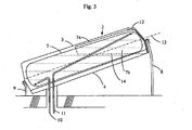
fig. 3 represents a cross section of the solar collector offig. 1 along line III-III. - In
fig. 1 a top view of asolar collector 1 according to the invention is shown. Thesolar collector 1 comprises ahousing 2 which comprises a transparent cap 3, which is suitably manufactured out of perspex, and a bottom plate 4 (fig. 2 and3 ). Within the housing 2 astorage tank 5 is situated. During operation, thisstorage tank 5 is directly heated by solar radiation and in order to efficiently absorb this, it is provided with an absorbing layer (not shown further), which is known in itself. The absorbing layer is, for example, a spectral selective coating which radiates little heat. Such a coating is known fromDE4433863 . In order to increase the thermal yield, thesolar collector 1 also comprises amirror 6, preferably a mathematicallyinvolute mirror 6. This concentrates light and reflects it onto thestorage tank 5, also onto the bottom thereof. For feeding of (cold) water, afeed pipe 10 is provided which discharges in the lowest part of thestorage tank 5. For the discharge of (hot) water adischarge pipe 11 is provided, which has an inlet at the higher end of thestorage tank 5. The solar collector described so far is known from the prior art. - In accordance with the present invention a
shielding 7 is provided at the higher end, between thestorage tank 5 and the transparent cap 3. In accordance with a possible embodiment the shielding is made of insulating material, such as glass wool, mineral wool etc. Insulating material is in particular useful in those countries where a lot of radiant energy is available per se (e.g. Spain), but where heat radiation during the night leads to a large drop of the water temperature. In addition, by using ashielding 7 in the form of an insulating material, the likelihood of overheating of the upper water layer in thestorage tank 5 is reduced since the volume of water covered by the insulating material will be more homogenous with respect to its temperature. - In order to optimally use the surface of the solar collector it is preferred, however, that the shielding is optically transparent.
- The
shielding 7 takes up at least part of the higher end of thestorage tank 5, such that convection between the storage tank and the transparent cap 3 is inhibited at the higher end. It is essential that theshielding 7 not only leaves uncovered at least part of the lower end of thestorage tank 5, but also increases the access of solar radiation to the storage tank at the side of the involute mirror, as a result of which light can reach thestorage tank 5 without hindrance, thanks to the part that is left free. Comparing the known solar collector to the present invention, the latter has less loss of light, heat losses are counteracted effectively, especially at the location where thestorage tank 5 is hottest and thus loses the most heat - being the water that will be used by the consumer - and it saves materials since theshielding 7 is smaller. Where in the present application in conjunction with the term "shielding" the covering of a volume of the storage tank is mentioned, then the open bottom of the shielding is regarded to be a limiting plane of the volume of content of the shielding. That part of the volume of the storage tank that is present within the shielding defined as here, is the volume encompassed by the shielding. Where in the present application a plane parallel to the involute mirror is mentioned, it will be easy for the person of ordinary skill in the art to determine the location of a flat plane that complies therewith. The ordinary person skilled in the art could use math to do so, but the practitioner having a more practical attitude will use the basic knowledge that when the surface of the shadow of a mirror that is turned towards the sun is the greatest, the mirror and a flat plate, which is also held such that its shadow is at its greatest, are parallel relative to each other. - The
solar collector 1 according to the invention will be positioned such that thestorage tank 5 is at an angle. For arrangement on the floor or on a flat roof or the like (fig. 3 ), thesolar collector 1 will be provided with legs 8, 9 or the like. It is also possible to position thesolar collector 1 with one end on an elevation, such as a small wall. Thesolar collector 1 may also be positioned on the sloped roof of a house. - When positioning the
solar collector 1 according to the invention such that thestorage tank 5 is at an angle, an increased yield will be achieved, as is known per se. Not only because of a better absorption of solar radiation (in areas outside the tropics), but also by more effiently using the formation of layers of hot water on top of water that is less hot. However, in case of an optically transparent shielding according to the invention, this could cause the problem of the water in the highly situated end of thestorage tank 5 starting to boil. In accordance with a preferred embodiment therefore apart 12 of the shielding 7 is optically opaque such that 2 to 5% of the most highly situated volume of thestorage tank 5 is covered by the opticallyopaque part 7. - In
figure 3 a preferred embodiment of the solar collector according to the invention is shown. Animaginary plane 13 through the central axis of thestorage tank 5, divides the shielding 7 in anupper part 7a and a lower part 7b, wherein the volume of the part of thestorage tank 5 covered by theupper part 7a is larger than that of the lower part 7b. Theupper part 7a holds the air which otherwise, due to convection, would reach the cap 3 where it would give off heat to the environment. Advantageously, thelower edge 14 of the shielding 7 is substantially horizontal, that is, having an angle of ±30° at the most, preferably ±20° at the most and most preferably not exceeding ±10° relative to the horizontal, after positioning the solar collector. In the embodiment illustrated infig. 3 the angle forming the lower edge with the horizontal is approximately 6°. As will be clear to the practitioner, for that matter, an angle with the horizontal is any angle, whether it is positive (ascending) or negative (descending). By now and then using the ± symbol this aspect is underlined. As will be clear to the person of ordinary skill in the art, the lower edge is that edge of the shielding that mainly determines the capture of hot air under the shielding. The angle is determined by the lowest and the highest part of that edge.
Claims (8)
- Solar collector having an integrated heat storage, said solar collector comprising a housing (2) which comprises a bottom plate (4) and a transparent cap (3), where in the housing (2) between an involute mirror (6) and the transparent cap (3) a storage tank (5) for storage of water is disposed, the solar collector being arranged, in use, to be at an angle with the horizontal such that the storage tank (5) has a higher end and a lower end, and wherein between the storage tank (5) and the transparent cap (3) a shielding (7) is provided for reducing heat losses, said shielding (7) being arranged at the higher end, between the storage tank (5) and the transparent cap (3), and the shielding (7) covering at least part of the higher end of the storage tank (5) such that at the higher end convection between the storage tank (5) and the transparent cap (3) is inhibited characterized in that the shielding (7) leaves at least part of the lower end uncovered whereby 20 to 60% of the volume of the storage tank (5) is covered by the shielding (7), and an imaginary plane (13) through the central axis of the storage tank (5), which plane is parallel with respect to the plane of the involute mirror (6), divides the shielding (7) into a part (7a) situated near the transparent cap (3) and a part (7b) near the involute mirror (6), wherein the volume of the storage tank (5) encompassed by said first part (7a) is at least 15% larger than that of said latter part (7b).
- Solar collector according to claim 1, wherein at least part of the surface of the shielding (7) is optically transparent.
- Solar collector according to claim 2, wherein part of the shielding (7) is optically opaque, such that 2 to 5% of the most highly situated volume of the storage tank (5), is covered by the optically opaque part.
- Solar collector according to any of the preceding claims, characterized in that said first part (7a) covers at least 30%, and more preferably at least 50%, more volume than the second part (7b).
- Solar collector according to any of the preceding claims, characterized in that the shielding (7) has a lower edge that is substantially horizontal, that is, having an angle of 20° at the most with respect to the horizontal.
- Solar collector according to claim 5, characterized in that the lower edge is at an angle of 10° at the most with respect to the horizontal.
- Solar collector according to any of the preceding claims, characterized in that the shielding (7) is fashioned out of polycarbonate.
- Method for placing a solar collector according to any of the claims 1 to 7, characterized in that it it is positioned such that the lower edge of the shielding (7) is at an angle with the horizontal of ±30° at the most, preferably ±20° at the most and most preferably not exceeding ±10°.
Applications Claiming Priority (2)
| Application Number | Priority Date | Filing Date | Title |
|---|---|---|---|
| NL1030094A NL1030094C2 (en) | 2005-10-03 | 2005-10-03 | Solar collector with integrated heat storage III. |
| PCT/NL2006/000495 WO2007040389A1 (en) | 2005-10-03 | 2006-10-02 | Solar collector with integrated heat storage |
Publications (3)
| Publication Number | Publication Date |
|---|---|
| EP1931925A1 EP1931925A1 (en) | 2008-06-18 |
| EP1931925B1 true EP1931925B1 (en) | 2009-11-18 |
| EP1931925B8 EP1931925B8 (en) | 2010-02-10 |
Family
ID=37709590
Family Applications (1)
| Application Number | Title | Priority Date | Filing Date |
|---|---|---|---|
| EP06799484A Not-in-force EP1931925B8 (en) | 2005-10-03 | 2006-10-02 | Solar collector with integrated heat storage |
Country Status (12)
| Country | Link |
|---|---|
| US (1) | US20080308092A1 (en) |
| EP (1) | EP1931925B8 (en) |
| JP (1) | JP2009510385A (en) |
| CN (1) | CN101273237A (en) |
| AT (1) | ATE449293T1 (en) |
| AU (1) | AU2006297981A1 (en) |
| DE (1) | DE602006010582D1 (en) |
| ES (1) | ES2336368T3 (en) |
| IL (1) | IL190128A0 (en) |
| NL (1) | NL1030094C2 (en) |
| RU (1) | RU2008117414A (en) |
| WO (1) | WO2007040389A1 (en) |
Families Citing this family (2)
| Publication number | Priority date | Publication date | Assignee | Title |
|---|---|---|---|---|
| RU2329437C1 (en) * | 2007-06-04 | 2008-07-20 | Борис Иванович Казанджан | Solar collector (options) and method of solar shell production |
| IL234308A (en) * | 2014-08-26 | 2015-08-31 | Ofer Zvulun | Liquid solar heating system |
Family Cites Families (18)
| Publication number | Priority date | Publication date | Assignee | Title |
|---|---|---|---|---|
| US735321A (en) * | 1902-09-02 | 1903-08-04 | Frank Walker | Combined solar and artificial heat water-heater. |
| US1889238A (en) * | 1927-05-07 | 1932-11-29 | Automatic Electric Heater Comp | Solar heater |
| IL47486A (en) * | 1974-06-21 | 1979-01-31 | Hastwell P J | Solar generator panel for heating water |
| US4027653A (en) * | 1975-10-10 | 1977-06-07 | Gershon Meckler | Solar energy collector |
| US4055161A (en) * | 1975-12-16 | 1977-10-25 | Jones Robert L | Solar energy collector and sun tracking concentrator |
| US4033325A (en) * | 1976-05-11 | 1977-07-05 | James Edwin Walker | Fluid sheet solar collector |
| IT1079881B (en) * | 1976-07-07 | 1985-05-13 | Broken Hill Pty Co Ltd | SOLAR ENERGY COLLECTOR GROUP |
| US4134389A (en) * | 1977-05-02 | 1979-01-16 | Mcclintock Michael | Solar energy collector |
| US4236506A (en) * | 1978-12-29 | 1980-12-02 | Roark Charles F | Solar energy collector |
| AU530878B2 (en) * | 1979-11-05 | 1983-08-04 | Mills, C.J. | Solar heat exchanger |
| US4355629A (en) * | 1980-11-24 | 1982-10-26 | Cornell Iii S Douglas | Superior performance passive solar water heater |
| US4413618A (en) * | 1981-11-04 | 1983-11-08 | King Energy Systems, Inc. | Solar collector |
| US4598450A (en) * | 1983-05-02 | 1986-07-08 | Fafco, Inc. | Method for fabricating a solar energy collector assembly utilizing a specifically designed fluid storage arrangement |
| US4520795A (en) * | 1983-12-09 | 1985-06-04 | Parkyn William A | Solar collector having tank and glazing construction |
| US4586227A (en) * | 1984-05-07 | 1986-05-06 | Cornell S Douglas | Method of making a solar water heater |
| US4642413A (en) * | 1985-10-11 | 1987-02-10 | Energy Conversion Devices, Inc. | Power generating optical filter |
| FR2591323B1 (en) * | 1985-12-09 | 1988-03-25 | Dubois Christian | SOLAR STORAGE WATER HEATER |
| NL1000357C2 (en) * | 1995-05-12 | 1996-11-13 | Zonne En Nederland B V | Radiant heating device. |
-
2005
- 2005-10-03 NL NL1030094A patent/NL1030094C2/en not_active IP Right Cessation
-
2006
- 2006-10-02 DE DE602006010582T patent/DE602006010582D1/en active Active
- 2006-10-02 RU RU2008117414/06A patent/RU2008117414A/en not_active Application Discontinuation
- 2006-10-02 JP JP2008533278A patent/JP2009510385A/en active Pending
- 2006-10-02 ES ES06799484T patent/ES2336368T3/en active Active
- 2006-10-02 AT AT06799484T patent/ATE449293T1/en not_active IP Right Cessation
- 2006-10-02 US US12/088,885 patent/US20080308092A1/en not_active Abandoned
- 2006-10-02 WO PCT/NL2006/000495 patent/WO2007040389A1/en not_active Ceased
- 2006-10-02 EP EP06799484A patent/EP1931925B8/en not_active Not-in-force
- 2006-10-02 CN CNA200680035104XA patent/CN101273237A/en active Pending
- 2006-10-02 AU AU2006297981A patent/AU2006297981A1/en not_active Abandoned
-
2008
- 2008-03-12 IL IL190128A patent/IL190128A0/en unknown
Also Published As
| Publication number | Publication date |
|---|---|
| WO2007040389A1 (en) | 2007-04-12 |
| US20080308092A1 (en) | 2008-12-18 |
| ATE449293T1 (en) | 2009-12-15 |
| NL1030094C2 (en) | 2007-04-04 |
| JP2009510385A (en) | 2009-03-12 |
| CN101273237A (en) | 2008-09-24 |
| IL190128A0 (en) | 2008-08-07 |
| EP1931925A1 (en) | 2008-06-18 |
| RU2008117414A (en) | 2009-11-10 |
| AU2006297981A1 (en) | 2007-04-12 |
| ES2336368T3 (en) | 2010-04-12 |
| DE602006010582D1 (en) | 2009-12-31 |
| EP1931925B8 (en) | 2010-02-10 |
Similar Documents
| Publication | Publication Date | Title |
|---|---|---|
| EP1931925B1 (en) | Solar collector with integrated heat storage | |
| CN102393082A (en) | Solar water boiler | |
| KR101404375B1 (en) | Solar heating system | |
| CN105042885A (en) | Concentrating type flat-plate solar collector | |
| KR20100067519A (en) | Evacuated tubular solar collector | |
| CN102944073B (en) | Temperature solar water heater in family expenses | |
| CN115493131A (en) | Flat-plate type medium-high temperature solar steam device | |
| CN202109668U (en) | High-temperature solar water heater | |
| HK1122094A (en) | Solar collector with integrated heat storage | |
| CN2293779Y (en) | Light reflection thermal-arrest apparatus for solar-energy water heater | |
| CN2800162Y (en) | Solar water heater | |
| CN104422152B (en) | Condenser groove solar thermal collector high temperature hot-water heating system | |
| CN2044702U (en) | Combined focus type solar water heater | |
| CN211695453U (en) | Heat collector | |
| CN205048752U (en) | A concentrating flat solar collector | |
| WO2012032330A2 (en) | An energy collector device | |
| CN201242299Y (en) | Solar vacuum tube with reflector | |
| JP3575674B2 (en) | Hot water tank type solar water heater | |
| CN203619312U (en) | Solar steam kettle | |
| KR200307903Y1 (en) | Cylindrical Solar Hot Water Heating System | |
| JPS5930849Y2 (en) | solar water heater | |
| TWI361674B (en) | ||
| CN201764723U (en) | A Solar Ring Heat Pipe Concentrating Collector with Tracking Function | |
| CN205227863U (en) | Solar energy collection pipe with good spotlight nature | |
| CN209263382U (en) | A kind of vertical solar water heater |
Legal Events
| Date | Code | Title | Description |
|---|---|---|---|
| PUAI | Public reference made under article 153(3) epc to a published international application that has entered the european phase |
Free format text: ORIGINAL CODE: 0009012 |
|
| 17P | Request for examination filed |
Effective date: 20080328 |
|
| AK | Designated contracting states |
Kind code of ref document: A1 Designated state(s): AT BE BG CH CY CZ DE DK EE ES FI FR GB GR HU IE IS IT LI LT LU LV MC NL PL PT RO SE SI SK TR |
|
| GRAP | Despatch of communication of intention to grant a patent |
Free format text: ORIGINAL CODE: EPIDOSNIGR1 |
|
| GRAS | Grant fee paid |
Free format text: ORIGINAL CODE: EPIDOSNIGR3 |
|
| GRAA | (expected) grant |
Free format text: ORIGINAL CODE: 0009210 |
|
| AK | Designated contracting states |
Kind code of ref document: B1 Designated state(s): AT BE BG CH CY CZ DE DK EE ES FI FR GB GR HU IE IS IT LI LT LU LV MC NL PL PT RO SE SI SK TR |
|
| REG | Reference to a national code |
Ref country code: GB Ref legal event code: FG4D |
|
| REG | Reference to a national code |
Ref country code: CH Ref legal event code: EP |
|
| REG | Reference to a national code |
Ref country code: IE Ref legal event code: FG4D |
|
| RAP2 | Party data changed (patent owner data changed or rights of a patent transferred) |
Owner name: ITHO B.V. |
|
| REF | Corresponds to: |
Ref document number: 602006010582 Country of ref document: DE Date of ref document: 20091231 Kind code of ref document: P |
|
| NLT2 | Nl: modifications (of names), taken from the european patent patent bulletin |
Owner name: ITHO B.V. Effective date: 20091223 |
|
| REG | Reference to a national code |
Ref country code: GB Ref legal event code: 732E Free format text: REGISTERED BETWEEN 20100204 AND 20100211 |
|
| REG | Reference to a national code |
Ref country code: ES Ref legal event code: FG2A Ref document number: 2336368 Country of ref document: ES Kind code of ref document: T3 |
|
| LTIE | Lt: invalidation of european patent or patent extension |
Effective date: 20091118 |
|
| PG25 | Lapsed in a contracting state [announced via postgrant information from national office to epo] |
Ref country code: LT Free format text: LAPSE BECAUSE OF FAILURE TO SUBMIT A TRANSLATION OF THE DESCRIPTION OR TO PAY THE FEE WITHIN THE PRESCRIBED TIME-LIMIT Effective date: 20091118 Ref country code: SE Free format text: LAPSE BECAUSE OF FAILURE TO SUBMIT A TRANSLATION OF THE DESCRIPTION OR TO PAY THE FEE WITHIN THE PRESCRIBED TIME-LIMIT Effective date: 20091118 Ref country code: PT Free format text: LAPSE BECAUSE OF FAILURE TO SUBMIT A TRANSLATION OF THE DESCRIPTION OR TO PAY THE FEE WITHIN THE PRESCRIBED TIME-LIMIT Effective date: 20100318 Ref country code: FI Free format text: LAPSE BECAUSE OF FAILURE TO SUBMIT A TRANSLATION OF THE DESCRIPTION OR TO PAY THE FEE WITHIN THE PRESCRIBED TIME-LIMIT Effective date: 20091118 Ref country code: IS Free format text: LAPSE BECAUSE OF FAILURE TO SUBMIT A TRANSLATION OF THE DESCRIPTION OR TO PAY THE FEE WITHIN THE PRESCRIBED TIME-LIMIT Effective date: 20100318 |
|
| PG25 | Lapsed in a contracting state [announced via postgrant information from national office to epo] |
Ref country code: CY Free format text: LAPSE BECAUSE OF FAILURE TO SUBMIT A TRANSLATION OF THE DESCRIPTION OR TO PAY THE FEE WITHIN THE PRESCRIBED TIME-LIMIT Effective date: 20091118 Ref country code: SI Free format text: LAPSE BECAUSE OF FAILURE TO SUBMIT A TRANSLATION OF THE DESCRIPTION OR TO PAY THE FEE WITHIN THE PRESCRIBED TIME-LIMIT Effective date: 20091118 Ref country code: PL Free format text: LAPSE BECAUSE OF FAILURE TO SUBMIT A TRANSLATION OF THE DESCRIPTION OR TO PAY THE FEE WITHIN THE PRESCRIBED TIME-LIMIT Effective date: 20091118 Ref country code: LV Free format text: LAPSE BECAUSE OF FAILURE TO SUBMIT A TRANSLATION OF THE DESCRIPTION OR TO PAY THE FEE WITHIN THE PRESCRIBED TIME-LIMIT Effective date: 20091118 |
|
| PG25 | Lapsed in a contracting state [announced via postgrant information from national office to epo] |
Ref country code: BE Free format text: LAPSE BECAUSE OF FAILURE TO SUBMIT A TRANSLATION OF THE DESCRIPTION OR TO PAY THE FEE WITHIN THE PRESCRIBED TIME-LIMIT Effective date: 20091118 Ref country code: AT Free format text: LAPSE BECAUSE OF FAILURE TO SUBMIT A TRANSLATION OF THE DESCRIPTION OR TO PAY THE FEE WITHIN THE PRESCRIBED TIME-LIMIT Effective date: 20091118 |
|
| PG25 | Lapsed in a contracting state [announced via postgrant information from national office to epo] |
Ref country code: RO Free format text: LAPSE BECAUSE OF FAILURE TO SUBMIT A TRANSLATION OF THE DESCRIPTION OR TO PAY THE FEE WITHIN THE PRESCRIBED TIME-LIMIT Effective date: 20091118 Ref country code: DK Free format text: LAPSE BECAUSE OF FAILURE TO SUBMIT A TRANSLATION OF THE DESCRIPTION OR TO PAY THE FEE WITHIN THE PRESCRIBED TIME-LIMIT Effective date: 20091118 Ref country code: EE Free format text: LAPSE BECAUSE OF FAILURE TO SUBMIT A TRANSLATION OF THE DESCRIPTION OR TO PAY THE FEE WITHIN THE PRESCRIBED TIME-LIMIT Effective date: 20091118 Ref country code: BG Free format text: LAPSE BECAUSE OF FAILURE TO SUBMIT A TRANSLATION OF THE DESCRIPTION OR TO PAY THE FEE WITHIN THE PRESCRIBED TIME-LIMIT Effective date: 20100218 |
|
| PG25 | Lapsed in a contracting state [announced via postgrant information from national office to epo] |
Ref country code: SK Free format text: LAPSE BECAUSE OF FAILURE TO SUBMIT A TRANSLATION OF THE DESCRIPTION OR TO PAY THE FEE WITHIN THE PRESCRIBED TIME-LIMIT Effective date: 20091118 Ref country code: CZ Free format text: LAPSE BECAUSE OF FAILURE TO SUBMIT A TRANSLATION OF THE DESCRIPTION OR TO PAY THE FEE WITHIN THE PRESCRIBED TIME-LIMIT Effective date: 20091118 |
|
| PLBE | No opposition filed within time limit |
Free format text: ORIGINAL CODE: 0009261 |
|
| STAA | Information on the status of an ep patent application or granted ep patent |
Free format text: STATUS: NO OPPOSITION FILED WITHIN TIME LIMIT |
|
| 26N | No opposition filed |
Effective date: 20100819 |
|
| PG25 | Lapsed in a contracting state [announced via postgrant information from national office to epo] |
Ref country code: GR Free format text: LAPSE BECAUSE OF FAILURE TO SUBMIT A TRANSLATION OF THE DESCRIPTION OR TO PAY THE FEE WITHIN THE PRESCRIBED TIME-LIMIT Effective date: 20100219 |
|
| PGFP | Annual fee paid to national office [announced via postgrant information from national office to epo] |
Ref country code: IT Payment date: 20101028 Year of fee payment: 5 |
|
| PG25 | Lapsed in a contracting state [announced via postgrant information from national office to epo] |
Ref country code: MC Free format text: LAPSE BECAUSE OF NON-PAYMENT OF DUE FEES Effective date: 20101031 |
|
| REG | Reference to a national code |
Ref country code: CH Ref legal event code: PL |
|
| PG25 | Lapsed in a contracting state [announced via postgrant information from national office to epo] |
Ref country code: LI Free format text: LAPSE BECAUSE OF NON-PAYMENT OF DUE FEES Effective date: 20101031 Ref country code: CH Free format text: LAPSE BECAUSE OF NON-PAYMENT OF DUE FEES Effective date: 20101031 |
|
| PG25 | Lapsed in a contracting state [announced via postgrant information from national office to epo] |
Ref country code: IE Free format text: LAPSE BECAUSE OF NON-PAYMENT OF DUE FEES Effective date: 20101002 |
|
| PGFP | Annual fee paid to national office [announced via postgrant information from national office to epo] |
Ref country code: GB Payment date: 20110830 Year of fee payment: 6 Ref country code: TR Payment date: 20110922 Year of fee payment: 6 |
|
| PGFP | Annual fee paid to national office [announced via postgrant information from national office to epo] |
Ref country code: ES Payment date: 20111018 Year of fee payment: 6 |
|
| PGFP | Annual fee paid to national office [announced via postgrant information from national office to epo] |
Ref country code: FR Payment date: 20120203 Year of fee payment: 6 |
|
| PGFP | Annual fee paid to national office [announced via postgrant information from national office to epo] |
Ref country code: DE Payment date: 20110907 Year of fee payment: 6 |
|
| PG25 | Lapsed in a contracting state [announced via postgrant information from national office to epo] |
Ref country code: HU Free format text: LAPSE BECAUSE OF FAILURE TO SUBMIT A TRANSLATION OF THE DESCRIPTION OR TO PAY THE FEE WITHIN THE PRESCRIBED TIME-LIMIT Effective date: 20100519 Ref country code: LU Free format text: LAPSE BECAUSE OF NON-PAYMENT OF DUE FEES Effective date: 20101002 |
|
| GBPC | Gb: european patent ceased through non-payment of renewal fee |
Effective date: 20121002 |
|
| REG | Reference to a national code |
Ref country code: FR Ref legal event code: ST Effective date: 20130628 |
|
| PG25 | Lapsed in a contracting state [announced via postgrant information from national office to epo] |
Ref country code: DE Free format text: LAPSE BECAUSE OF NON-PAYMENT OF DUE FEES Effective date: 20130501 Ref country code: GB Free format text: LAPSE BECAUSE OF NON-PAYMENT OF DUE FEES Effective date: 20121002 |
|
| REG | Reference to a national code |
Ref country code: DE Ref legal event code: R119 Ref document number: 602006010582 Country of ref document: DE Effective date: 20130501 |
|
| PG25 | Lapsed in a contracting state [announced via postgrant information from national office to epo] |
Ref country code: FR Free format text: LAPSE BECAUSE OF NON-PAYMENT OF DUE FEES Effective date: 20121031 Ref country code: IT Free format text: LAPSE BECAUSE OF NON-PAYMENT OF DUE FEES Effective date: 20121002 |
|
| REG | Reference to a national code |
Ref country code: ES Ref legal event code: FD2A Effective date: 20140527 |
|
| PG25 | Lapsed in a contracting state [announced via postgrant information from national office to epo] |
Ref country code: TR Free format text: LAPSE BECAUSE OF NON-PAYMENT OF DUE FEES Effective date: 20121002 Ref country code: ES Free format text: LAPSE BECAUSE OF NON-PAYMENT OF DUE FEES Effective date: 20121003 |
|
| PGFP | Annual fee paid to national office [announced via postgrant information from national office to epo] |
Ref country code: NL Payment date: 20141031 Year of fee payment: 9 |
|
| REG | Reference to a national code |
Ref country code: NL Ref legal event code: MM Effective date: 20151101 |
|
| PG25 | Lapsed in a contracting state [announced via postgrant information from national office to epo] |
Ref country code: NL Free format text: LAPSE BECAUSE OF NON-PAYMENT OF DUE FEES Effective date: 20151101 |