EP1932221B1 - Elektromotor mit einer Anschlussplatte - Google Patents
Elektromotor mit einer Anschlussplatte Download PDFInfo
- Publication number
- EP1932221B1 EP1932221B1 EP06819059A EP06819059A EP1932221B1 EP 1932221 B1 EP1932221 B1 EP 1932221B1 EP 06819059 A EP06819059 A EP 06819059A EP 06819059 A EP06819059 A EP 06819059A EP 1932221 B1 EP1932221 B1 EP 1932221B1
- Authority
- EP
- European Patent Office
- Prior art keywords
- stator
- electric motor
- rotor
- sensor
- sensors
- Prior art date
- Legal status (The legal status is an assumption and is not a legal conclusion. Google has not performed a legal analysis and makes no representation as to the accuracy of the status listed.)
- Active
Links
Images






Classifications
-
- H—ELECTRICITY
- H01—ELECTRIC ELEMENTS
- H01R—ELECTRICALLY-CONDUCTIVE CONNECTIONS; STRUCTURAL ASSOCIATIONS OF A PLURALITY OF MUTUALLY-INSULATED ELECTRICAL CONNECTING ELEMENTS; COUPLING DEVICES; CURRENT COLLECTORS
- H01R12/00—Structural associations of a plurality of mutually-insulated electrical connecting elements, specially adapted for printed circuits, e.g. printed circuit boards [PCB], flat or ribbon cables, or like generally planar structures, e.g. terminal strips, terminal blocks; Coupling devices specially adapted for printed circuits, flat or ribbon cables, or like generally planar structures; Terminals specially adapted for contact with, or insertion into, printed circuits, flat or ribbon cables, or like generally planar structures
- H01R12/50—Fixed connections
- H01R12/51—Fixed connections for rigid printed circuits or like structures
-
- H—ELECTRICITY
- H02—GENERATION; CONVERSION OR DISTRIBUTION OF ELECTRIC POWER
- H02K—DYNAMO-ELECTRIC MACHINES
- H02K29/00—Motors or generators having non-mechanical commutating devices, e.g. discharge tubes or semiconductor devices
- H02K29/06—Motors or generators having non-mechanical commutating devices, e.g. discharge tubes or semiconductor devices with position sensing devices
- H02K29/08—Motors or generators having non-mechanical commutating devices, e.g. discharge tubes or semiconductor devices with position sensing devices using magnetic effect devices, e.g. Hall-plates, magneto-resistors
-
- H—ELECTRICITY
- H01—ELECTRIC ELEMENTS
- H01R—ELECTRICALLY-CONDUCTIVE CONNECTIONS; STRUCTURAL ASSOCIATIONS OF A PLURALITY OF MUTUALLY-INSULATED ELECTRICAL CONNECTING ELEMENTS; COUPLING DEVICES; CURRENT COLLECTORS
- H01R13/00—Details of coupling devices of the kinds covered by groups H01R12/70 or H01R24/00 - H01R33/00
- H01R13/66—Structural association with built-in electrical component
- H01R13/665—Structural association with built-in electrical component with built-in electronic circuit
- H01R13/6658—Structural association with built-in electrical component with built-in electronic circuit on printed circuit board
-
- H—ELECTRICITY
- H01—ELECTRIC ELEMENTS
- H01R—ELECTRICALLY-CONDUCTIVE CONNECTIONS; STRUCTURAL ASSOCIATIONS OF A PLURALITY OF MUTUALLY-INSULATED ELECTRICAL CONNECTING ELEMENTS; COUPLING DEVICES; CURRENT COLLECTORS
- H01R13/00—Details of coupling devices of the kinds covered by groups H01R12/70 or H01R24/00 - H01R33/00
- H01R13/66—Structural association with built-in electrical component
- H01R13/665—Structural association with built-in electrical component with built-in electronic circuit
- H01R13/6683—Structural association with built-in electrical component with built-in electronic circuit with built-in sensor
-
- H—ELECTRICITY
- H02—GENERATION; CONVERSION OR DISTRIBUTION OF ELECTRIC POWER
- H02K—DYNAMO-ELECTRIC MACHINES
- H02K5/00—Casings; Enclosures; Supports
- H02K5/04—Casings or enclosures characterised by the shape, form or construction thereof
- H02K5/22—Auxiliary parts of casings not covered by groups H02K5/06-H02K5/20, e.g. shaped to form connection boxes or terminal boxes
- H02K5/225—Terminal boxes or connection arrangements
Definitions
- the present invention relates to an electric motor with a connection plate.
- one or more sensors are provided.
- the sensors detect the position of the rotor relative to the stator field. This size is essential to be able to control the stator currents as a function of the rotor position and thereby be able to achieve a maximum engine torque.
- PCB printed Circuit Board
- These PCBs or the sensors of the PCB are inserted between the stator teeth or stator poles in order to be able to detect the magnetic field of the rotor magnets.
- the PCB is provided with the sensors on the end shield in dedicated plastic mounts to detect the field of additional magnet ring provided on the shaft outside the motor or motor housing. In both cases, the sensors provided on the PCB must be connected via relatively long connecting lines with control electronics.
- the Hall sensor unit comprises a housing that includes a printed circuit board with a Hall sensor.
- the stator of the electric motor has gaps for mounting the Hall sensor unit.
- a rotation angle sensor which is a rotor unit and a stator unit having at least two stator sub-elements, which are arranged while leaving a distance recess to each other, wherein in the spacer recess at least one Hall sensor for determining the angle of rotation of the rotor unit is arranged.
- the invention has for its object to overcome these disadvantages and in particular to provide an engine component with a simple structure available.
- the invention is based on the finding that this object can be achieved by extending the functionality of a component provided in a conventional manner in an electric motor.
- the internal terminal plate is referred to in the context of this invention, via which the winding wires of the stator windings can be connected.
- This internal connection plate may include an external terminal to which the external lines are connected, or be connected to this for example via a plug connection. Due to the inventive design of the connection plate, this can serve as a holder and fixation for sensors in addition to the function of contacting the coil windings.
- the receiving opening in the receiving area can in particular serve to pass the sensors through them.
- the receiving openings may be provided with a flange or web which protects a guided through the receiving opening sensor at least from one side.
- a receiving opening is provided in the terminal plate and thus the sensors can face to the side facing away from the receiving area, lines from the sensors or from the PCB to contacts and / or control electronics can be performed on the side of the connection plate the Sensors and thus facing away from the stator.
- the PCB can thereby be protected by a bearing plate provided on the motor.
- connection plate has an L-shape, wherein at least the receiving area is provided in one leg and at least the contacts for connecting or contacting the coil windings of the electric motor are provided in the further leg.
- the contacts can be arranged at the edge of the stator, where the terminal plate with an outer terminal directly, that can be brought without wires in connection.
- the receiving area can be guided over the end face of the stator and so the sensors are reliably positioned at the point where they are to monitor or detect the position of the rotor.
- the receiving area has at least one recess for receiving a printed circuit board.
- This printed circuit board or PCB which can serve to contact the sensors and can additionally carry sensor elements, can thus be held in a protected position and the position of the PCB can be predetermined by the depression.
- connection plate on the stator in addition at least one fastening element for fastening the connection plate on the stator, in particular on the stator can be provided.
- this fastener an immediate fixation of the terminal plate is made possible on the stator and thus accurately determined due to the integration of the sensor holder in the terminal plate and the position of the sensors.
- connection plate preferably covers a part of the circumference of the stator end face.
- this embodiment has a simplified construction. It will only material is needed to form the receiving area in which the PCB can be accommodated.
- a printed circuit board is held in the receiving area, which has at least one contact plug for contacting or connecting to the contacts of the connection plate.
- At least one guide for a connecting line between a printed circuit board and the at least one contact can be provided in the receiving region.
- This guide can be realized by partitions in the recess of the receiving area. In these guides, connection lines provided on the PCB can run and thus be protected.
- the invention relates to an electric motor, in particular a commutated electric motor, with a stator, a rotor and at least one sensor for detecting the rotor position.
- the electric motor is characterized in that it comprises at least one connecting plate according to the invention with at least one receiving area with at least one receiving opening for the at least one sensor.
- the electric motor may have a simpler structure than conventional electric motors. In particular, separate fastening devices for holding the sensors can be omitted.
- the electric motor has a magnetic ring between the rotor and a bearing bearing a bearing plate.
- This magnet ring which serves to monitor the rotor position, can be provided inside the motor housing in the embodiment of the motor according to the invention, since the sensors are integrated with the connection plate of the stator. Through this installation location of the magnetic ring, the overall length of the electric motor compared to conventional motors, in which the magnetic ring is to be provided outside the bearing plate is reduced.
- This mounting recess in particular represents a slot into which a part of the connection plate can be inserted.
- connection plate 1 is shown in a perspective view.
- the connection plate 1 consists of a receiving region 2 and a contact region 3.
- contacts 4 are provided, via which the electrical connection of the coil windings of the stator of an electric motor with leads (not shown) can be produced.
- the receiving region 2 essentially has a trough shape, wherein the depression of the trough in the front region, that is to say in the part of the receiving region 2 which is at a distance from the contact region 3, serves to receive a printed circuit board (PCB) 5.
- PCB printed circuit board
- a connecting part 6 is provided which constitutes a part of the receiving area 2.
- In this connecting part 6 run in the trough shape partitions 10, between which connecting lines 9 are from the PCB 5 and extend to the contacts 4 in the contact region 3 of the terminal plate 1.
- the front area of the reception area 2 has a greater width than the connection part 6. At the end of the reception area 2 facing away from the contact area 3, this has a rounding.
- the receiving openings or passage openings 8 are provided for sensors 22.
- three receiving openings 8 are provided.
- the arrangement of the sensors 22 and the PCB 5 in the receiving area 2 can be made from FIG. 3 remove.
- the receiving openings 8, as well as the adjacent thereto protective wall 11 for the sensors 22 can be seen.
- the distribution of the receiving openings 8 along the edge of the receiving area 2 results in particular from the FIG. 4 ,
- the position of the receiving openings 8, the positions of the sensors 22 are clearly defined, so that position inaccuracies in the assembly of the PCB 5 can be compensated.
- FIG. 3 shows two connecting wedges 7 are provided at the contact region 3, which is a leg of the substantially L-shaped connection plate 1.
- the terminal plate 1 can be attached to a stator 13, which will be explained later in more detail.
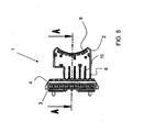
- FIG. 5 is a plan view of a connection plate 1 without PCB 5 shown.
- the partitions 10 can be seen in the connecting part 6, which connects the front area of the receiving area 2 and the contact area 3. Through these partitions 10 guides for the connecting lines 9 of the PCB 5 are formed.
- the arrangement of the sensors 22 on the PCB 5 also results from the FIG. 6 , Like this one FIG. 6 can be seen, protrude the sensors 22 in one direction from the PCB 5 upwards. In the same direction, the connection lines 9 are fixed to the PCB 5.
- This PCB 5 can be used in the Receiving area 2 of the connection plate 1 are introduced, wherein the sensors 22 protrude through the receiving openings 8 in the receiving area 2 and can be contacted by means of the connecting lines 9 in the contact area 3 via conventional connecting means.
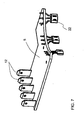
- FIG. 7 another embodiment of the PCB 5 is shown.
- this has a shape that corresponds to the entire receiving area 2 of the terminal plate 1.
- the PCB 5 also extends over the connecting part 6 and fills it. Partitions 10 are not provided when using such a PCB 5.
- contact plugs 12 are provided which are soldered onto the PCB 5. These contact plugs 12 can be connected to contacts 4 in the contact region 3 or introduced into it.
- connection plate 1 The attachment of the connection plate 1 to the stator assembly 23 of an electric motor is in FIG. 9 shown.
- the connection plate 1 is introduced by means of the fastening wedges 7 in correspondingly provided stator slots 16.
- the contact region 3 lies on the edge of the stator core 13 and is thus accessible for connection to a so-called outer terminal without the use of wires and the like.
- the receiving region 2 of the connection plate 1 extends radially and substantially parallel to the end face of the stator core 13.
- the sensors 22 are radially spaced apart on the inner edge of the stator 23, in particular of the stator poles 15, due to the length of the receiving region 2 in the illustrated embodiment Staggered inside.
- FIG. 9 is a partial cross section through the stator assembly 23 from FIG. 8 shown.
- the connection plate 1 is attached to the stator core 13 via the fastening wedges 7.
- the receiving region extends at a distance from the end face of the stator 23.
- the PCB 5 faces away from the stator, or is replaced by the receiving region 2 of this separated.
- the sensors 22 extend through the receiving openings 8 in the direction of the stator 23.
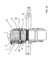
- FIG. 10 is a partial cross section through a stator assembly 23 with rotor 17 received therein with rotor shaft 18 shown.
- the rotor magnets or poles 24 are provided.
- a magnetic ring 19 is provided on the rotor shaft 18, which has a smaller diameter than the rotor 17.
- the magnetic ring 19 in this case has a corresponding number of poles as the rotor stack 17.
- the receiving area 2 of the provided on the stator 13 connection plate 1 extends from the contact area 3 to the outer periphery of the magnetic ring 19. This results in the sensors 22 in the receiving area 2 held PCB 5 in the immediate vicinity of the magnet ring 19 and thereby can detect the rotor position.
- FIG. 11 shows this stator-rotor assembly in the housing, which includes in particular a bearing plate 21.
- This bearing plate 21 is mounted on the rotor shaft 18 via the bearing 20.
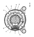
- FIG. 12 shown top view of this embodiment of the electric motor 25 are on the one hand, the stator windings 14 can be seen. Furthermore, the position of the magnet ring 19 is indicated and provided in the rotor 17 rotor main poles or rotor magnet 24.
- the sensors 22 which are held on the provided in the receiving area 2 PCB 5, in this case lie between the magnet 24 of the rotor 17 and the magnetic ring 19th ,
- the position of the rotor 17 via the sensors 22, by monitoring the rotor main poles 24 is determined.
- the sensors 22 are aligned with the poles 24 of the rotor 17.
- this alignment is achieved by the choice of the length of the receiving area 2.
- the receiving area 2 extends from the contact area 3 only up to the magnetic poles 24 of the rotor 17, whereby the receiving openings 8 in the terminal plate 1, in which the sensors 22 held are, the position of the magnets 24 corresponds.
- a separate magnetic ring is not provided.
- the present invention it is possible to achieve sensor positioning with minimal tolerances between the stator pack and the engine end shield and between the engine end shield and plastic sensor holders.
- the invention allows a minimum tolerance between the stator teeth or the stator poles and the sensor or the sensors.
- the invention also offers extremely short connecting lines for connecting the sensors to the contact area of the internal connection plate.
- two functions can be integrated in the invention in a motor component, namely the function of the connection plate and the sensor holder. There are no screws for fixing the sensor holder to the motor necessary and also a mechanical protection of the sensor holder and the sensors and the PCB can be ensured by the engine end shield.
- a shorter shaft for the motor can also be used, since a magnetic ring can be provided on a free part of the rotor shaft between the bearing and the rotor core.
- the total number of motor connection plates, contact types for motor connection plates, screws for fixing the holder and plastic parts is reduced by integrating the sensor holder into the internal motor connection plate.
Landscapes
- Engineering & Computer Science (AREA)
- Microelectronics & Electronic Packaging (AREA)
- Power Engineering (AREA)
- Motor Or Generator Frames (AREA)
- Dry Shavers And Clippers (AREA)
- Insulation, Fastening Of Motor, Generator Windings (AREA)
Description
- Die vorliegende Erfindung betrifft einen Elektromotor mit einer Anschlussplatte.
- Insbesondere bei einigen elektrisch kommutierten Motoren mit einem Magnetrotor oder einem Dauermagneten in dem Rotor sind ein oder mehreren Sensoren vorgesehen. Über die Sensoren wird die Lage des Rotors zum Statorfeld erfasst. Diese Größe ist wesentlich um die Statorströme in Abhängigkeit der Rotorlage steuern zu können und dadurch ein maximales Motormoment erreichen zu können.
- Diese Sensoren sowie die notwendigen elektrischen Komponenten sind in der Regel auf einer kleinen Leiterplatte (Printed Circuit Board), die im Folgenden auch als PCB bezeichnet wird, vorgesehen. Diese PCB beziehungsweise die Sensoren des PCB werden zwischen die Statorzähne beziehungsweise Statorpole eingebracht, um das Magnetfeld der Rotormagneten erkennen zu können. Alternativ wird die PCB mit den Sensoren auf dem Lagerschild in speziell dafür vorgesehenen Plastikhalterungen vorgesehen, um das Feld eines zusätzlichen Magnetrings, der auf dem Schaft außerhalb des Motors beziehungsweise Motorgehäuses vorgesehen ist, zu erkennen. In beiden Fällen müssen die auf der PCB vorgesehenen Sensoren über relativ lange Verbindungsleitungen mit Steuerungselektronikelementen verbunden werden.
- Aus Dokument
US 4,998,865 A ist eine Pumpe mit einem Antriebsmotor bekannt, bei der eine Schaltungseinheit Leiterplatten beinhaltet, auf denen eine Vielzahl von Elementen zur Positionsbestimmung der Rotorpole aufgebracht sind. Diese Schaltungseinheit weist Anschlüsse auf, über die sie mit einer Spannungsversorgung und mit Statorwicklungen des Antriebsmotors verbunden ist. - Aus Dokument
US 6,354,162 A ist ein Elektromotor mit einer Hallsensoreinheit zur Positionsbestimmung der Rotormagneten bekannt. Die Hallsensoreinheit umfasst ein Gehäuse, das eine Leiterplatte mit einem Hallsensor beinhaltet. Der Stator des Elektromotors weist Lücken zur Befestigung der Hallsensoreinheit auf. - Aus Dokument
EP 1 054 237 A2 ist ein Drehwinkelsensor bekannt, der eine Rotoreinheit und eine Statoreinheit mit wenigstens zwei Statorteilelementen aufweist, die unter Belassung einer Abstandsausnehmung zueinander angeordnet sind, wobei in der Abstandsausnehmung wenigstens ein Hallsensor zur Bestimmung des Drehwinkels der Rotoreinheit angeordnet ist. - Die bekannten Lösungen weisen den Nachteil auf, dass hierbei hohe Erfassungstoleranzen der Rotorposition in Kauf genommen werden müssen. Zudem ist eine große Anzahl an Motorteilen erforderlich. So müssen insbesondere die Halterungen für die Sensoren und entsprechende Schrauben zur Befestigung vorgesehen sein.
- Der Erfindung liegt die Aufgabe zugrunde diese Nachteile zu beheben und insbesondere ein Motorbauteil mit einem einfachen Aufbau zur Verfügung zu stellen.
- Der Erfindung liegt die Erkenntnis zugrunde, dass diese Aufgabe gelöst werden kann, indem die Funktionalität eines in einem Elektromotor üblicher Weise vorgesehenen Bauteils erweitert wird.
- Die Aufgabe wird erfindungsgemäß durch einen Elektromotor mit den Merkmalen von Anspruch 1 gelöst.
- Als Anschlussplatte, die im Folgenden auch als Terminal bezeichnet wird, wird im Sinne dieser Erfindung die interne Klemmenplatte bezeichnet, über die die Wicklungsdrähte der Statorwicklungen angeschlossen werden können. Diese interne Anschlussplatte kann ein externes Terminal, an dem die externen Leitungen angeschlossen werden, beinhalten oder mit diesem beispielsweise über eine Steckverbindung verbunden sein. Durch die erfindungsgemäße Ausgestaltung der Anschlussplatte, kann diese neben der Funktion der Kontaktierung der Spulenwicklungen auch als Halterung und Fixierung für Sensoren dienen. Durch die Integration des Sensorhalters in die Anschlussplatte kann eine separate Haltevorrichtung für die Sensoren, die in der Regel Schrauben und andere Komponenten erfordern würde, entfallen. Die Aufnahmeöffnung in dem Aufnahmebereich kann insbesondere dazu dienen die Sensoren durch diese hindurchzuführen. Zusätzlich können die Aufnahmeöffnungen mit einem Flansch oder Steg versehen sein, der einen durch die Aufnahmeöffnung hindurch geführten Sensor zumindest von einer Seite schützt. Indem in der Anschlussplatte mindestens eine Aufnahmeöffnung vorgesehen ist und die Sensoren somit zu der Seite weisen können, die dem Aufnahmebereich abgewandt ist, können Leitungen von den Sensoren beziehungsweise von der PCB zu Kontakten und/oder einer Steuerungselektronik an der Seite der Anschlussplatte geführt werden die den Sensoren und damit dem Stator abgewandt ist. Die PCB kann dadurch durch ein an dem Motor vorgesehenes Lagerschild geschützt werden.
- Erfindungsgemäß weist die Anschlussplatte eine L-Form auf, wobei in einem Schenkel zumindest der Aufnahmebereich und in dem weiteren Schenkel zumindest die Kontakte zum Anschließen beziehungsweise Kontaktieren der Spulenwicklungen des Elektromotors vorgesehen sind. Auf diese Weise können die Kontakte am Rand des Stators angeordnet werden, wo die Anschlussplatte mit einem äußeren Terminal unmittelbar, das heißt ohne Drähte in Verbindung gebracht werden kann. Weiterhin kann der Aufnahmebereich über die Stirnseite des Stators geführt werden und so die Sensoren auf zuverlässige Weise an der Stelle positioniert werden, an der diese die Position des Rotors überwachen beziehungsweise erkennen sollen.
- Gemäß einer Ausführungsform weist der Aufnahmebereich zumindest eine Vertiefung zur Aufnahme einer Leiterplatte auf. Diese Leiterplatte beziehungsweise PCB, die zum Kontaktieren der Sensoren dienen kann und zusätzlich Sensorikelemente tragen kann, kann somit an einer geschützten Position gehalten werden und die Position der PCB durch die Vertiefung vorgegeben werden.
- An dem Schenkel, in dem die Kontakte vorgesehen sind, kann zusätzlich zumindest ein Befestigungselement zur Befestigung der Anschlussplatte am Stator, insbesondere am Statorpaket vorgesehen sein. Durch dieses Befestigungselement wird eine unmittelbare Fixierung der Anschlussplatte an dem Stator ermöglicht und aufgrund der Integration des Sensorhalters in der Anschlussplatte somit auch die Position der Sensoren genau festgelegt. Durch diese Art der Anschlussplatte und deren Fixierung an dem Stator können Toleranzen der Rotorpositionserfassung eliminiert werden.
- Der Aufnahmebereich der Anschlussplatte deckt vorzugsweise einen Teil des Umfangs der Statorstirnseite ab. Im Gegensatz zu einer Vorrichtung, die die gesamte Stirnseite des Stators abdeckt, weist diese Ausführungsform einen vereinfachten Aufbau auf. Es wird lediglich Material benötigt, um den Aufnahmebereich, in dem die PCB aufgenommen werden kann, zu bilden.
- Gemäß einer Ausführungsform wird in dem Aufnahmebereich eine Leiterplatte gehalten, die zumindest einen Kontaktstecker zum Kontaktieren mit beziehungsweise Anschließen an den Kontakten der Anschlussplatte aufweist. Durch diese Ausgestaltung können separate Verbindungsdrähte für die Sensoren, die ebenfalls auf der PCB angeordnet sind, vollständig entfallen. Zudem ist nur eine Art der Verbindung in dem gesamten Bauteil realisiert, da auch die Kontaktierung der Wicklungen des Stators über entsprechende Kontaktstecker erfolgen kann.
- Alternativ kann in dem Aufnahmebereich zumindest eine Führung für eine Verbindungsleitung zwischen einer Leiterplatte und dem mindestens einen Kontakt vorgesehen sein. Diese Führung kann durch Trennwände in der Vertiefung des Aufnahmebereiches realisiert sein. In diesen Führungen können Verbindungsleitungen, die an der PCB vorgesehen sind, verlaufen und somit geschützt werden.
- Die Erfindung betrifft einen Elektromotor, insbesondere einen kommuntierten Elektromotor, mit einem Stator, einem Rotor und zumindest einem Sensor zur Erfassung der Rotorposition. Der Elektromotor zeichnet sich dadurch aus, dass dieser zumindest eine erfindungsgemäße Anschlussplatte mit zumindest einem Aufnahmebereich mit zumindest einer Aufnahmeöffnung für den zumindest einen Sensor umfasst. Durch die erfindungsgemäße Anschlussplatte kann der Elektromotor einen einfacheren Aufbau als herkömmliche Elektromotoren besitzen. Insbesondere können gesonderte Befestigungsvorrichtungen zur Halterung der Sensoren entfallen.
- Gemäß einer Ausführungsform weist der Elektromotor zwischen dem Rotor und einem ein Lagerschild tragenden Lager einen Magnetring auf. Dieser zur Überwachung der Rotorposition dienende Magnetring kann bei der erfindungsgemäßen Ausgestaltung des Motors innerhalb des Motorgehäuses vorgesehen werden, da die Sensoren mit der Anschlussplatte des Stators integriert sind. Durch diesen Einbauort des Magnetrings verringert sich die Gesamtbaulänge des Elektromotors gegenüber herkömmlichen Motoren, bei denen der Magnetring außerhalb des Lagerschildes vorzusehen ist.
- Am äußeren Umfang des Statorpaketes ist bei dem erfindungsgemäßen Elektromotor vorzugsweise zumindest eine Befestigungsaussparung zur Befestigung von mindestens einer Anschlussplatte vorgesehen. Diese Befestigungsaussparung stellt insbesondere einen Schlitz dar, in den ein Teil der Anschlussplatte eingeführt werden kann. Hierdurch werden der Halt der Anschlussplatte und damit die Position der Sensoren fixiert.
- Die vorliegende Erfindung wird im Folgenden anhand der beiliegenden Zeichnungen erneut im Detail erläutert. Es zeigen:
-
Figur 1 : eine schematische Perspektivansicht einer Ausführungsform der Anschlussplatte; -
Figur 2 : eine Draufsicht auf eine die Anschlussplatte nachFigur 1 ; -
Figur 3 : eine Schnittansicht durch die Anschlussplatte nachFigur 1 entlang der Schnittlinie A-A inFigur 2 ; -
Figur 4 : eine Untersicht der Anschlussplatte nachFigur 1 ; -
Figur 5 : eine Draufsicht auf eine Ausführungsform der erfindungsgemäßen Anschlussplatte ohne Leiterplatte; -
Figur 6 : eine schematische Perspektivansicht der ersten Ausführungsform der Leiterplatte mit Anschlüssen und Sensoren; -
Figur 7 : eine schematische Perspektivansicht einer weiteren Ausführungsform der Leiterplatte mit Anschlüssen und Sensoren; -
Figur 8 : eine Draufsicht auf den Statoraufbau eines Elektromotors mit Anschlussplatte; -
Figur 9 : eine Teilschnittansicht des Aufbaus ausFigur 8 ; -
Figur 10 : eine schematische Teilschnittansicht eines Stator-Rotor-Aufbaus mit Rotorschaft; -
Figur 11 : eine schematische Teilschnittansicht des Stator-Rotor-Aufbaus nachFigur 10 mit Gehäuse; -
Figur 12 : eine schematische Draufsicht auf den Stator-Rotor-Aufbau nachFigur 11 ; -
Figur 13 : eine schematische Teilschnittansicht einer weiteren Ausführungsform des Stator-Rotor-Aufbaus mit Gehäuse; und -
Figur 14 : eine schematische Draufsicht auf den Stator-Rotoraufbau nachFigur 13 . - In
Figur 1 ist eine Anschlussplatte 1 in perspektivischer Ansicht gezeigt. Die Anschlussplatte 1 besteht aus einem Aufnahmebereich 2 und einem Kontaktbereich 3. In dem Kontaktbereich 3 sind Kontakte 4 vorgesehen, über die der elektrische Anschluss der Spulenwicklungen des Stators eines Elektromotors mit Zuleitungen (nicht gezeigt) hergestellt werden kann. Der Aufnahmebereich 2 weist im Wesentlichen eine Wannenform auf, wobei die Vertiefung der Wanne in dem vorderen Bereich, das heißt in dem zu dem Kontaktbereich 3 beabstandeten Teil des Aufnahmebereiches 2 zur Aufnahme einer Leiterplatte (PCB) 5 dient. Zwischen diesem Teil des Aufnahmebereiches 2 und dem Kontaktbereich 3 ist ein Verbindungsteil 6 vorgesehen, das einen Bestandteil des Aufnahmebereiches 2 darstellt. In diesem Verbindungsteil 6 verlaufen in der Wannenform Trennwände 10, zwischen denen Verbindungsleitungen 9 von der PCB 5 liegen und bis zu den Kontakten 4 in dem Kontaktbereich 3 der Anschlussplatte 1 verlaufen. - Wie sich insbesondere aus der
Figur 2 , die eine Draufsicht auf die Anschlussplatte 1 darstellt, ergibt, besitzt der vordere Bereich des Aufnahmebereiches 2 eine größere Breite als das Verbindungsteil 6. An dem dem Kontaktbereich 3 abgewandten Ende des Aufnahmebereiches 2 weist dieser eine Rundung auf. Entlang dieser sind die Aufnahmeöffnungen beziehungsweise Durchlassöffnungen 8 für Sensoren 22 vorgesehen. In der dargestellten Ausführungsform sind drei Aufnahmeöffnungen 8 vorgesehen. Die Anordnung der Sensoren 22 und der PCB 5 in dem Aufnahmebereich 2 lässt sich aus derFigur 3 entnehmen. In dieserFigur 3 sind die Aufnahmeöffnungen 8, sowie die an diese angrenzende Schutzwand 11 für die Sensoren 22 zu erkennen. Die Verteilung der Aufnahmeöffnungen 8 entlang des Randes des Aufnahmebereiches 2 ergibt sich insbesondere aus derFigur 4 . Durch die Position der Aufnahmeöffnungen 8 sind die Positionen der Sensoren 22 eindeutig vorgegeben, so dass Positionsungenauigkeiten bei der Bestückung der PCB 5 ausgeglichen werden können. - Wie sich weiterhin aus
Figur 3 ergibt, sind an dem Kontaktbereich 3, der einen Schenkel der im Wesentlichen L-fömigen Anschlussplatte 1 darstellt, zwei Verbindungskeile 7 vorgesehen. Über diese Verbindungskeile 7 kann die Anschlussplatte 1 an einem Statorpaket 13 befestigt werden, was später genauer erläutert wird. - In
Figur 5 ist eine Draufsicht auf eine Anschlussplatte 1 ohne PCB 5 gezeigt. In dieser Ansicht lassen sich die Trennwände 10 in dem Verbindungsteil 6, das den vorderen Bereich des Aufnahmebereiches 2 und den Kontaktbereich 3 verbindet, erkennen. Durch diese Trennwände 10 werden Führungen für die Verbindungsleitungen 9 des PCB 5 gebildet. - Die Anordnung der Sensoren 22 auf der PCB 5 gemäß einer Ausführungsform ergibt sich auch aus der
Figur 6 . Wie sich dieserFigur 6 entnehmen lässt, ragen die Sensoren 22 in einer Richtung von der PCB 5 nach oben. In der gleichen Richtung sind die Verbindungsleitungen 9 an der PCB 5 befestigt. Diese PCB 5 kann in den Aufnahmebereich 2 der Anschlussplatte 1 eingebracht werden, wobei die Sensoren 22 durch die Aufnahmeöffnungen 8 in dem Aufnahmebereich 2 hindurch ragen und mittels der Verbindungsleitungen 9 im Kontaktbereich 3 über herkömmliche Verbindungsmittel kontaktiert werden können. Die inFigur 6 gezeigte PCB 5 mit den darauf getragenen Sensoren 22 kann somit vollständig in den Aufnahmebereich 2 der Anschlussplatte 1 aufgenommen werden, wobei die Länge der Verbindungsleitungen 9 lediglich der Länge des Verbindungsteils 6 und des Kontaktbereiches 3 entspricht und diese kurzen Verbindungsleitungen 9 zudem durch den Aufnahmebereich 2 und die darin vorgesehenen Trennwände 10 sicher geführt sind. - In der
Figur 7 ist eine weitere Ausführungsform der PCB 5 gezeigt. Hierbei besitzt diese eine Form, die dem gesamten Aufnahmebereich 2 der Anschlussplatte 1 entspricht. Insbesondere erstreckt sich die PCB 5 bei dieser Ausführungsform auch über das Verbindungsteil 6 und füllt dieses aus. Trennwände 10 sind bei der Verwendung einer solchen PCB 5 nicht vorzusehen. An dem dem Kontaktbereich 3 zugewandten Ende der PCB 5 sind Kontaktstecker 12 vorgesehen, die auf der PCB 5 verlötet sind. Diese Kontaktstecker 12 können mit Kontakten 4 in dem Kontaktbereich 3 verbunden beziehungsweise in diese eingeführt werden. - Die Anbringung der Anschlussplatte 1 an der Stator-Anordnung 23 eines Elektromotors ist in
Figur 9 gezeigt. Die Anschlussplatte 1 wird mittels der Befestigungskeile 7 in entsprechend dafür vorgesehene Statorschlitze 16 eingebracht. In der befestigten Position liegt somit der Kontaktbereich 3 am Rande des Statorpaketes 13 und ist damit für die Verbindung mit einem so genannten äußeren Terminal ohne die Verwendung von Drähten und der gleichen zugänglich. Weiterhin erstreckt sich der Aufnahmebereich 2 der Anschlussplatte 1 radial und im Wesentlichen parallel zu der Stirnseite des Statorpaketes 13. Die Sensoren 22 sind aufgrund der Länge des Aufnahmebereiches 2 bei der dargestellten Ausführungsform zu der Innenkante des Stators 23, insbesondere der Statorpole 15, beabstandet radial nach Innen versetzt angeordnet. - In der
Figur 9 ist ein Teilquerschnitt durch die Stator-Anordnung 23 ausFigur 8 gezeigt. Wie sich hieraus erkennen lässt, ist die Anschlussplatte 1 über die Befestigungskeile 7 an dem Statorpaket 13 befestigt. Der Aufnahmebereich verläuft beabstandet zu der Stirnseite des Stators 23. Hierbei ist die PCB 5 dem Stator abgewandt, beziehungsweise wird durch den Aufnahmebereich 2 von diesem getrennt. Die Sensoren 22 erstrecken sich durch die Aufnahmeöffnungen 8 in Richtung auf den Stator 23. - In
Figur 10 ist ein Teilquerschnitt durch eine Stator-Anordnung 23 mit darin aufgenommenem Rotor 17 mit Rotorschaft 18 gezeigt. In dem Rotor 17 sind die Rotormagnete beziehungsweise Pole 24 vorgesehen. Vor dem Rotor 17 ist auf dem Rotorschaft 18 ein Magnetring 19 vorgesehen, der einen geringeren Durchmesser als der Rotor 17 aufweist. Der Magnetring 19 besitzt hierbei eine entsprechende Anzahl an Polen wie das Rotorpaket 17. Der Aufnahmebereich 2 der an dem Statorpaket 13 vorgesehenen Anschlussplatte 1 erstreckt sich von dem Kontaktbereich 3 bis zu dem äußeren Umfang des Magnetrings 19. Hierdurch liegen die Sensoren 22 der in dem Aufnahmebereich 2 gehaltenen PCB 5 in unmittelbarer Nähe des Magnetrings 19 und können dadurch die Rotorposition erfassen. -
Figur 11 zeigt diese Stator-Rotor-Anordnung in dem Gehäuse, das insbesondere ein Lagerschild 21 umfasst. Dieses Lagerschild 21 ist über das Lager 20 auf dem Rotoschaft 18 gelagert. Der Magnetring 19, der vor dem Rotor 17 angeordnet ist, liegt somit zwischen dem Rotor 17 und dem Lagerschild 21. Da der Magnetring 19 in dem Gehäuse auf einem freien Stück des Rotorschaftes 18 aufgenommen werden kann weist der so gebildete Motor 25 eine geringe Baulänge auf. - In der in
Figur 12 gezeigten Draufsicht auf diese Ausführungsform des Elektromotors 25 sind zum einen die Statorwicklungen 14 zu erkennen. Weiterhin ist die Position des Magnetrings 19 angedeutet und die in dem Rotor 17 vorgesehenen Rotorhauptpole beziehungsweise Rotormagneten 24. Die Sensoren 22, die auf der in dem Aufnahmebereich 2 vorgesehenen PCB 5 gehalten sind, liegen hierbei zwischen den Magneten 24 des Rotors 17 und dem Magnetring 19. - Bei der in
Figur 13 gezeigten weiteren Ausführungsform wird die Position des Rotors 17 über die Sensoren 22, durch Überwachung der Rotorhauptpole 24 bestimmt. In diesem Fall sind die Sensoren 22 mit den Polen 24 des Rotors 17 ausgerichtet. Wie sich aus der Draufsicht inFigur 14 ergibt, wird diese Ausrichtung durch die Wahl der Länge des Aufnahmebereiches 2 erzielt. In der dargestellten Ausführungsform erstreckt sich der Aufnahmebereich 2 von dem Kontaktbereich 3 aus nur bis zu den Magnetpolen 24 des Rotors 17, wodurch die Aufnahmeöffnungen 8 in der Anschlussplatte 1, in denen die Sensoren 22 gehalten sind, der Position der Magnete 24 entspricht. Bei dieser Ausführungsform ist ein gesonderter Magnetring nicht vorgesehen. - Mit der vorliegenden Erfindung ist es möglich eine Sensorpositionierung mit minimalen Toleranzen zwischen dem Statorpaket und dem Motorlagerschild sowie zwischen dem Motorlagerschild und Plastiksensorhaltern zu erzielen. Die Erfindung erlaubt eine minimale Toleranz zwischen den Statorzähnen beziehungsweise den Statorpolen und dem Sensor oder den Sensoren. Die Erfindung bietet darüber hinaus extrem kurze Verbindungsleitungen für die Verbindung der Sensoren mit dem Kontaktbereich der internen Anschlussplatte. Zudem können bei der Erfindung in einem Motorbauteil zwei Funktionen integriert werden, nämlich die Funktion der Anschlussplatte und der des Sensorhalters. Es sind keine Schrauben zur Fixierung des Sensorhalters an dem Motor notwendig und zudem kann ein mechanischer Schutz des Sensorhalters und der Sensoren und der PCB durch das Motorlagerschild gewährleistet werden. Mit der Erfindung kann zudem ein kürzerer Schaft für den Motor verwendet werden, da ein Magnetring auf einem freien Teil des Rotorschaftes zwischen dem Lager und dem Rotorpaket vorgesehen werden kann. Schließlich wird die Gesamtzahl der Motoranschlussplatten, der Kontakttypen für Motoranschlussplatten, Schrauben für die Fixierung des Halters und Plastikteile durch die Integration des Sensorhalters in die interne Motoranschlussplatte reduziert.
Claims (7)
- Elektromotor mit einem Statorpaket (13), mit einem Rotor (17), mit zumindest einem Sensor (22) zur Erfassung der Rotorposition und mit einer Anschlussplatte (1) für Statorwicklungen (14) des Statorpakets (13), wobei die Anschlussplatte (1) einen Kontaktbereich (3) mit Kontakten (4) zum Anschluss der Statorwicklungen (14) an externe Leitungen aufweist, wobei die Anschlussplatte (1) zumindest einen Aufnahmebereich (2) für den zumindest einen Sensor (22) zur Überwachung der Rotorposition aufweist, dadurch gekennzeichnet, dass der Aufnahmebereich (2) zumindest eine Aufnahmeöffnung (8) für den zumindest einen Sensor (22) zur Überwachung der Rotorposition aufweist, durch die der Sensor (22) hindurchgeführt ist, dass die Anschlussplatte (1) zumindest ein Befestigungselement (7) aufweist, mit dem sie in einer Befestigungsaussparung (16) am äußeren Umfang des Statorpakets (13) des Elektromotors befestigt ist, so dass der Kontaktbereich (3) am Rand des Statorpakets (13) liegt, und dass sich bei der am Statorpaket (13) befestigten Anschlussplatte (1) der Aufnahmebereich (2) von dem Kontaktbereich (3) radial und im Wesentlichen parallel und beabstandet zur Stirnseite des Statorpakets (13) erstreckt, so dass der Sensor (22) zu einer Innenkante des Statorpakets (13) beabstandet radial nach Innen versetzt angeordnet ist.
- Elektromotor nach Anspruch 1, dadurch gekennzeichnet, dass der Aufnahmebereich (2) zumindest eine Vertiefung aufweist, in der eine Leiterplatte (5), die mit dem Sensor (22) bestückt ist, gehaltert ist.
- Elektromotor nach einem der Ansprüche 1 oder 2, dadurch gekennzeichnet, dass die Anschlussplatte (1) eine L-Form aufweist, wobei in einem Schenkel zumindest der Aufnahmebereich (2) und in dem weiteren Schenkel die Kontakte (4) zur Kontaktierung der Statorwicklungen (14) des Elektromotors (25) und das Befestigungselement (7) zur Befestigung am Stator (23) vorgesehen sind.
- Elektromotor nach einem der Ansprüche 1 bis 3, dadurch gekennzeichnet, dass der Aufnahmebereich (2) einen Teil der Statorstirnseite abdeckt.
- Elektromotor nach einem der Ansprüche 2 bis 4, dadurch gekennzeichnet, dass die Leiterplatte (5) zumindest einen Kontaktstecker (12) zum Kontaktieren mit den Kontakten (4) aufweist.
- Elektromotor nach einem der Ansprüche 2 bis 5, dadurch gekennzeichnet, dass in dem Aufnahmebereich (2) zumindest eine Führung (10) für eine Verbindungsleitung (9) zwischen der Leiterplatte (5) und den Kontakten (4) vorgesehen ist.
- Elektromotor nach einem der vorhergehenden Ansprüche, dadurch gekennzeichnet, dass dieser zwischen dem Rotor (17) und einem ein Lagerschild (21) tragenden Lager (20) einen Magnetring (19) aufweist.
Applications Claiming Priority (2)
| Application Number | Priority Date | Filing Date | Title |
|---|---|---|---|
| DE102005046759A DE102005046759A1 (de) | 2005-09-29 | 2005-09-29 | Anschlussplatte für Elektromotor und Elektromotor |
| PCT/EP2006/066823 WO2007036548A1 (de) | 2005-09-29 | 2006-09-28 | Anschlussplatte für elektromotor und elektromotor |
Publications (2)
| Publication Number | Publication Date |
|---|---|
| EP1932221A1 EP1932221A1 (de) | 2008-06-18 |
| EP1932221B1 true EP1932221B1 (de) | 2011-03-02 |
Family
ID=37517159
Family Applications (1)
| Application Number | Title | Priority Date | Filing Date |
|---|---|---|---|
| EP06819059A Active EP1932221B1 (de) | 2005-09-29 | 2006-09-28 | Elektromotor mit einer Anschlussplatte |
Country Status (9)
| Country | Link |
|---|---|
| US (1) | US20080252160A1 (de) |
| EP (1) | EP1932221B1 (de) |
| KR (1) | KR20080063278A (de) |
| CN (1) | CN101278448B (de) |
| AT (1) | ATE500637T1 (de) |
| AU (1) | AU2006296557A1 (de) |
| DE (2) | DE102005046759A1 (de) |
| ES (1) | ES2359876T3 (de) |
| WO (1) | WO2007036548A1 (de) |
Cited By (1)
| Publication number | Priority date | Publication date | Assignee | Title |
|---|---|---|---|---|
| WO2014005961A1 (de) | 2012-07-04 | 2014-01-09 | Hella Kgaa Hueck & Co. | Drehwinkelsensor |
Families Citing this family (12)
| Publication number | Priority date | Publication date | Assignee | Title |
|---|---|---|---|---|
| US7581991B2 (en) * | 2007-07-17 | 2009-09-01 | Gm Global Technology Operations, Inc. | Vehicle electric current connector assembly with electric current sensors |
| DE102007041334A1 (de) * | 2007-08-31 | 2009-03-05 | Siemens Ag Österreich | Leiterplatte für bürstenlose Gleichstrommotore |
| JP4628460B2 (ja) * | 2008-10-22 | 2011-02-09 | 三菱電機株式会社 | 回転電機、及びその製造方法 |
| EP2214296B1 (de) * | 2009-02-03 | 2012-01-25 | Robert Bosch Gmbh | Elektronisch geschaltetes Motoraggregat |
| US8179004B2 (en) * | 2009-11-06 | 2012-05-15 | Shop Vac Corporation | Motor assembly with switch module |
| CN201947080U (zh) * | 2011-01-28 | 2011-08-24 | 中山大洋电机制造有限公司 | 一种无刷电机转子结构 |
| US8523576B2 (en) | 2011-10-24 | 2013-09-03 | GM Global Technology Operations LLC | Connector for coupling an electric motor to a power source |
| CN103855847B (zh) * | 2012-11-30 | 2016-09-07 | 中山大洋电机股份有限公司 | 一种电机引线固定夹组件及其应用的电机 |
| FR3011145B1 (fr) * | 2013-09-20 | 2017-04-14 | Valeo Equip Electr Moteur | Dispositif de determination d'une position angulaire et/ou de la vitesse de rotation d'un rotor d'un moteur electrique polyphase et moteur electrique correspondant |
| US9929608B2 (en) * | 2014-02-07 | 2018-03-27 | Nidec Motor Corporation | Stator cage for large motor |
| CN104836387A (zh) * | 2014-12-19 | 2015-08-12 | 广东威灵电机制造有限公司 | 电机 |
| JP2016162908A (ja) * | 2015-03-03 | 2016-09-05 | アズビル株式会社 | 回路基板の接続構造 |
Citations (1)
| Publication number | Priority date | Publication date | Assignee | Title |
|---|---|---|---|---|
| EP1054237A2 (de) * | 1999-05-17 | 2000-11-22 | AB Elektronik GmbH | Drehwinkelsensor |
Family Cites Families (12)
| Publication number | Priority date | Publication date | Assignee | Title |
|---|---|---|---|---|
| US4998865A (en) | 1988-07-11 | 1991-03-12 | Aisan Kogyo Kabushiki Kaisha | Brushless DC pump with enclosed circuit board |
| DE4227062C1 (de) * | 1992-08-15 | 1994-03-17 | Steinmueller Kg Atlanta Kabel | Dichtende Anschlußplatte für einen Elektromotor |
| WO1997009659A1 (en) * | 1995-09-05 | 1997-03-13 | Cts Corporation | Rotary position sensor with insert molded coil winding |
| US5770902A (en) * | 1995-11-02 | 1998-06-23 | Globe Motors | Motor termination board |
| JP3394407B2 (ja) * | 1996-12-25 | 2003-04-07 | 株式会社三協精機製作所 | モータ駆動装置 |
| DE10125581C2 (de) * | 2001-05-25 | 2003-05-08 | Webasto Vehicle Sys Int Gmbh | Antriebsvorrichtung |
| US6354162B1 (en) | 2001-05-30 | 2002-03-12 | General Electric Company | Sensor mounting assembly and method |
| DE10315871A1 (de) * | 2003-04-08 | 2004-10-21 | Ina-Schaeffler Kg | Bürstenloser Gleichstrommotor (BLDC-Motor) |
| US6975052B2 (en) * | 2003-08-29 | 2005-12-13 | Japan Servo Co., Ltd. | Terminal arrangement of motor and capacitor motor |
| JP4496010B2 (ja) * | 2004-05-20 | 2010-07-07 | 株式会社東芝 | モータ |
| DE102005012620A1 (de) * | 2005-03-18 | 2006-09-28 | Bühler Motor GmbH | Elektrischer Antrieb |
| US7413446B1 (en) * | 2007-05-14 | 2008-08-19 | Fci Americas Technology, Inc. | Electrical connector module |
-
2005
- 2005-09-29 DE DE102005046759A patent/DE102005046759A1/de not_active Withdrawn
-
2006
- 2006-09-28 KR KR1020087006753A patent/KR20080063278A/ko not_active Withdrawn
- 2006-09-28 US US12/088,605 patent/US20080252160A1/en not_active Abandoned
- 2006-09-28 ES ES06819059T patent/ES2359876T3/es active Active
- 2006-09-28 CN CN200680036002XA patent/CN101278448B/zh active Active
- 2006-09-28 AT AT06819059T patent/ATE500637T1/de active
- 2006-09-28 AU AU2006296557A patent/AU2006296557A1/en not_active Abandoned
- 2006-09-28 WO PCT/EP2006/066823 patent/WO2007036548A1/de not_active Ceased
- 2006-09-28 DE DE502006009020T patent/DE502006009020D1/de active Active
- 2006-09-28 EP EP06819059A patent/EP1932221B1/de active Active
Patent Citations (1)
| Publication number | Priority date | Publication date | Assignee | Title |
|---|---|---|---|---|
| EP1054237A2 (de) * | 1999-05-17 | 2000-11-22 | AB Elektronik GmbH | Drehwinkelsensor |
Cited By (2)
| Publication number | Priority date | Publication date | Assignee | Title |
|---|---|---|---|---|
| WO2014005961A1 (de) | 2012-07-04 | 2014-01-09 | Hella Kgaa Hueck & Co. | Drehwinkelsensor |
| DE102012105969A1 (de) | 2012-07-04 | 2014-01-09 | Hella Kgaa Hueck & Co. | Drehwinkelsensor |
Also Published As
| Publication number | Publication date |
|---|---|
| US20080252160A1 (en) | 2008-10-16 |
| DE502006009020D1 (de) | 2011-04-14 |
| DE102005046759A1 (de) | 2007-04-05 |
| WO2007036548A1 (de) | 2007-04-05 |
| CN101278448B (zh) | 2010-12-22 |
| AU2006296557A1 (en) | 2007-04-05 |
| CN101278448A (zh) | 2008-10-01 |
| KR20080063278A (ko) | 2008-07-03 |
| ATE500637T1 (de) | 2011-03-15 |
| ES2359876T3 (es) | 2011-05-27 |
| EP1932221A1 (de) | 2008-06-18 |
Similar Documents
| Publication | Publication Date | Title |
|---|---|---|
| EP2182616B1 (de) | Bürstenloser Gleichstrommotor | |
| DE102007044230B4 (de) | Drehmelder und bürstenfreier Motor | |
| EP1932221B1 (de) | Elektromotor mit einer Anschlussplatte | |
| DE2748543C2 (de) | ||
| DE3831551C2 (de) | Metallkernleiterplatte mit Ausnehmnung zur Aufnahme von Bauelementen | |
| DE102005013326B4 (de) | Elektrischer Motor | |
| DE60128530T2 (de) | Einbau einer Steuerelektronik für bürstenlose Gleichstrommotoren in ihren Kühlkörper | |
| EP0220447B1 (de) | Elektromotor, insbesondere dauermagneterregter Aussenläufermotor | |
| EP3939148B1 (de) | Antriebsvorrichtung mit einem bürstenlosen elektromotor | |
| DE102011002007A1 (de) | Motorisierte Gerätschaft | |
| DE2912802B1 (de) | Anordnung zum Verschalten der Wicklungsenden der Statorwicklung mit einem aeusseren Anschlusskabel in einem Elektro-Kleinmotor,insbesondere einem Aussenlaeufermotor | |
| DE102010017522A1 (de) | Antriebsvorrichtung und Halbleitermodul | |
| DE112006000828T5 (de) | Motorvorrichtung | |
| DE102011084763A1 (de) | Gehäuseteil für eine elektrische Maschine | |
| DE102015226511B4 (de) | Antriebsvorrichtung | |
| DE2543196A1 (de) | Schleifringlose elektrische maschine | |
| WO2019052782A1 (de) | Stator für eine elektrische maschine, eine elektrische maschine und verfahren zum herstellen eines solchen stators | |
| DE3805060A1 (de) | Elektromotor mit einem systemtraeger zur aufnahme von bauelementen, leiterbahnen und steuer- bzw. regelbausteinen | |
| DE102022210401A1 (de) | Motor | |
| DE102021105322A1 (de) | Motorsteuerungsvorrichtung | |
| EP4025874B1 (de) | Drehwinkelmessanordnung, drehwinkelmesssystem und elektromotor | |
| DE202009006871U1 (de) | Elektromotor | |
| DE102016105656A1 (de) | Verbindungsanordnung für einen elektromotor | |
| DE112014005305T5 (de) | Motor | |
| DE112018008135B4 (de) | Elektromotor |
Legal Events
| Date | Code | Title | Description |
|---|---|---|---|
| PUAI | Public reference made under article 153(3) epc to a published international application that has entered the european phase |
Free format text: ORIGINAL CODE: 0009012 |
|
| 17P | Request for examination filed |
Effective date: 20080429 |
|
| AK | Designated contracting states |
Kind code of ref document: A1 Designated state(s): AT BE BG CH CY CZ DE DK EE ES FI FR GB GR HU IE IS IT LI LT LU LV MC NL PL PT RO SE SI SK TR |
|
| 17Q | First examination report despatched |
Effective date: 20080801 |
|
| GRAP | Despatch of communication of intention to grant a patent |
Free format text: ORIGINAL CODE: EPIDOSNIGR1 |
|
| RTI1 | Title (correction) |
Free format text: ELECTRIC MOTOR WITH A CONNECTING PLATE |
|
| RTI1 | Title (correction) |
Free format text: ELECTRIC MOTOR WITH A CONNECTING PLATE |
|
| GRAS | Grant fee paid |
Free format text: ORIGINAL CODE: EPIDOSNIGR3 |
|
| GRAA | (expected) grant |
Free format text: ORIGINAL CODE: 0009210 |
|
| AK | Designated contracting states |
Kind code of ref document: B1 Designated state(s): AT BE BG CH CY CZ DE DK EE ES FI FR GB GR HU IE IS IT LI LT LU LV MC NL PL PT RO SE SI SK TR |
|
| REG | Reference to a national code |
Ref country code: GB Ref legal event code: FG4D Free format text: NOT ENGLISH |
|
| REG | Reference to a national code |
Ref country code: CH Ref legal event code: EP |
|
| REG | Reference to a national code |
Ref country code: IE Ref legal event code: FG4D Free format text: LANGUAGE OF EP DOCUMENT: GERMAN |
|
| REF | Corresponds to: |
Ref document number: 502006009020 Country of ref document: DE Date of ref document: 20110414 Kind code of ref document: P |
|
| REG | Reference to a national code |
Ref country code: DE Ref legal event code: R096 Ref document number: 502006009020 Country of ref document: DE Effective date: 20110414 |
|
| REG | Reference to a national code |
Ref country code: ES Ref legal event code: FG2A Ref document number: 2359876 Country of ref document: ES Kind code of ref document: T3 Effective date: 20110527 |
|
| REG | Reference to a national code |
Ref country code: NL Ref legal event code: VDEP Effective date: 20110302 |
|
| PG25 | Lapsed in a contracting state [announced via postgrant information from national office to epo] |
Ref country code: SE Free format text: LAPSE BECAUSE OF FAILURE TO SUBMIT A TRANSLATION OF THE DESCRIPTION OR TO PAY THE FEE WITHIN THE PRESCRIBED TIME-LIMIT Effective date: 20110302 Ref country code: GR Free format text: LAPSE BECAUSE OF FAILURE TO SUBMIT A TRANSLATION OF THE DESCRIPTION OR TO PAY THE FEE WITHIN THE PRESCRIBED TIME-LIMIT Effective date: 20110603 Ref country code: LV Free format text: LAPSE BECAUSE OF FAILURE TO SUBMIT A TRANSLATION OF THE DESCRIPTION OR TO PAY THE FEE WITHIN THE PRESCRIBED TIME-LIMIT Effective date: 20110302 Ref country code: LT Free format text: LAPSE BECAUSE OF FAILURE TO SUBMIT A TRANSLATION OF THE DESCRIPTION OR TO PAY THE FEE WITHIN THE PRESCRIBED TIME-LIMIT Effective date: 20110302 |
|
| REG | Reference to a national code |
Ref country code: SK Ref legal event code: T3 Ref document number: E 9370 Country of ref document: SK |
|
| LTIE | Lt: invalidation of european patent or patent extension |
Effective date: 20110302 |
|
| PG25 | Lapsed in a contracting state [announced via postgrant information from national office to epo] |
Ref country code: BG Free format text: LAPSE BECAUSE OF FAILURE TO SUBMIT A TRANSLATION OF THE DESCRIPTION OR TO PAY THE FEE WITHIN THE PRESCRIBED TIME-LIMIT Effective date: 20110602 Ref country code: NL Free format text: LAPSE BECAUSE OF FAILURE TO SUBMIT A TRANSLATION OF THE DESCRIPTION OR TO PAY THE FEE WITHIN THE PRESCRIBED TIME-LIMIT Effective date: 20110302 Ref country code: FI Free format text: LAPSE BECAUSE OF FAILURE TO SUBMIT A TRANSLATION OF THE DESCRIPTION OR TO PAY THE FEE WITHIN THE PRESCRIBED TIME-LIMIT Effective date: 20110302 Ref country code: SI Free format text: LAPSE BECAUSE OF FAILURE TO SUBMIT A TRANSLATION OF THE DESCRIPTION OR TO PAY THE FEE WITHIN THE PRESCRIBED TIME-LIMIT Effective date: 20110302 Ref country code: CY Free format text: LAPSE BECAUSE OF FAILURE TO SUBMIT A TRANSLATION OF THE DESCRIPTION OR TO PAY THE FEE WITHIN THE PRESCRIBED TIME-LIMIT Effective date: 20110302 |
|
| REG | Reference to a national code |
Ref country code: IE Ref legal event code: FD4D |
|
| PG25 | Lapsed in a contracting state [announced via postgrant information from national office to epo] |
Ref country code: IE Free format text: LAPSE BECAUSE OF FAILURE TO SUBMIT A TRANSLATION OF THE DESCRIPTION OR TO PAY THE FEE WITHIN THE PRESCRIBED TIME-LIMIT Effective date: 20110302 Ref country code: PT Free format text: LAPSE BECAUSE OF FAILURE TO SUBMIT A TRANSLATION OF THE DESCRIPTION OR TO PAY THE FEE WITHIN THE PRESCRIBED TIME-LIMIT Effective date: 20110704 Ref country code: EE Free format text: LAPSE BECAUSE OF FAILURE TO SUBMIT A TRANSLATION OF THE DESCRIPTION OR TO PAY THE FEE WITHIN THE PRESCRIBED TIME-LIMIT Effective date: 20110302 |
|
| PG25 | Lapsed in a contracting state [announced via postgrant information from national office to epo] |
Ref country code: CZ Free format text: LAPSE BECAUSE OF FAILURE TO SUBMIT A TRANSLATION OF THE DESCRIPTION OR TO PAY THE FEE WITHIN THE PRESCRIBED TIME-LIMIT Effective date: 20110302 Ref country code: RO Free format text: LAPSE BECAUSE OF FAILURE TO SUBMIT A TRANSLATION OF THE DESCRIPTION OR TO PAY THE FEE WITHIN THE PRESCRIBED TIME-LIMIT Effective date: 20110302 Ref country code: IS Free format text: LAPSE BECAUSE OF FAILURE TO SUBMIT A TRANSLATION OF THE DESCRIPTION OR TO PAY THE FEE WITHIN THE PRESCRIBED TIME-LIMIT Effective date: 20110702 |
|
| PLBE | No opposition filed within time limit |
Free format text: ORIGINAL CODE: 0009261 |
|
| STAA | Information on the status of an ep patent application or granted ep patent |
Free format text: STATUS: NO OPPOSITION FILED WITHIN TIME LIMIT |
|
| 26N | No opposition filed |
Effective date: 20111205 |
|
| PG25 | Lapsed in a contracting state [announced via postgrant information from national office to epo] |
Ref country code: DK Free format text: LAPSE BECAUSE OF FAILURE TO SUBMIT A TRANSLATION OF THE DESCRIPTION OR TO PAY THE FEE WITHIN THE PRESCRIBED TIME-LIMIT Effective date: 20110302 Ref country code: PL Free format text: LAPSE BECAUSE OF FAILURE TO SUBMIT A TRANSLATION OF THE DESCRIPTION OR TO PAY THE FEE WITHIN THE PRESCRIBED TIME-LIMIT Effective date: 20110302 |
|
| REG | Reference to a national code |
Ref country code: DE Ref legal event code: R097 Ref document number: 502006009020 Country of ref document: DE Effective date: 20111205 |
|
| BERE | Be: lapsed |
Owner name: BSH BOSCH UND SIEMENS HAUSGERATE G.M.B.H. Effective date: 20110930 |
|
| PG25 | Lapsed in a contracting state [announced via postgrant information from national office to epo] |
Ref country code: MC Free format text: LAPSE BECAUSE OF NON-PAYMENT OF DUE FEES Effective date: 20110930 |
|
| REG | Reference to a national code |
Ref country code: CH Ref legal event code: PL |
|
| PG25 | Lapsed in a contracting state [announced via postgrant information from national office to epo] |
Ref country code: BE Free format text: LAPSE BECAUSE OF NON-PAYMENT OF DUE FEES Effective date: 20110930 |
|
| PG25 | Lapsed in a contracting state [announced via postgrant information from national office to epo] |
Ref country code: CH Free format text: LAPSE BECAUSE OF NON-PAYMENT OF DUE FEES Effective date: 20110930 Ref country code: LI Free format text: LAPSE BECAUSE OF NON-PAYMENT OF DUE FEES Effective date: 20110930 |
|
| REG | Reference to a national code |
Ref country code: AT Ref legal event code: MM01 Ref document number: 500637 Country of ref document: AT Kind code of ref document: T Effective date: 20110928 |
|
| PG25 | Lapsed in a contracting state [announced via postgrant information from national office to epo] |
Ref country code: AT Free format text: LAPSE BECAUSE OF NON-PAYMENT OF DUE FEES Effective date: 20110928 |
|
| PG25 | Lapsed in a contracting state [announced via postgrant information from national office to epo] |
Ref country code: LU Free format text: LAPSE BECAUSE OF NON-PAYMENT OF DUE FEES Effective date: 20110928 |
|
| PG25 | Lapsed in a contracting state [announced via postgrant information from national office to epo] |
Ref country code: HU Free format text: LAPSE BECAUSE OF FAILURE TO SUBMIT A TRANSLATION OF THE DESCRIPTION OR TO PAY THE FEE WITHIN THE PRESCRIBED TIME-LIMIT Effective date: 20110302 |
|
| REG | Reference to a national code |
Ref country code: DE Ref legal event code: R081 Ref document number: 502006009020 Country of ref document: DE Owner name: BSH HAUSGERAETE GMBH, DE Free format text: FORMER OWNER: BSH BOSCH UND SIEMENS HAUSGERAETE GMBH, 81739 MUENCHEN, DE Effective date: 20150407 |
|
| REG | Reference to a national code |
Ref country code: ES Ref legal event code: PC2A Owner name: BSH HAUSGERATE GMBH Effective date: 20150609 |
|
| REG | Reference to a national code |
Ref country code: FR Ref legal event code: PLFP Year of fee payment: 10 |
|
| REG | Reference to a national code |
Ref country code: FR Ref legal event code: CD Owner name: BSH HAUSGERATE GMBH, DE Effective date: 20151022 |
|
| REG | Reference to a national code |
Ref country code: FR Ref legal event code: PLFP Year of fee payment: 11 |
|
| REG | Reference to a national code |
Ref country code: FR Ref legal event code: PLFP Year of fee payment: 12 |
|
| REG | Reference to a national code |
Ref country code: FR Ref legal event code: PLFP Year of fee payment: 13 |
|
| PGFP | Annual fee paid to national office [announced via postgrant information from national office to epo] |
Ref country code: DE Payment date: 20250930 Year of fee payment: 20 |
|
| PGFP | Annual fee paid to national office [announced via postgrant information from national office to epo] |
Ref country code: TR Payment date: 20250919 Year of fee payment: 20 |
|
| PGFP | Annual fee paid to national office [announced via postgrant information from national office to epo] |
Ref country code: GB Payment date: 20250923 Year of fee payment: 20 |
|
| PGFP | Annual fee paid to national office [announced via postgrant information from national office to epo] |
Ref country code: FR Payment date: 20250924 Year of fee payment: 20 |
|
| PGFP | Annual fee paid to national office [announced via postgrant information from national office to epo] |
Ref country code: SK Payment date: 20250918 Year of fee payment: 20 |
|
| PGFP | Annual fee paid to national office [announced via postgrant information from national office to epo] |
Ref country code: IT Payment date: 20250930 Year of fee payment: 20 |
|
| PGFP | Annual fee paid to national office [announced via postgrant information from national office to epo] |
Ref country code: ES Payment date: 20251020 Year of fee payment: 20 |