EP1932412B1 - Landwirtschaftliche Maschine - Google Patents
Landwirtschaftliche Maschine Download PDFInfo
- Publication number
- EP1932412B1 EP1932412B1 EP20070023390 EP07023390A EP1932412B1 EP 1932412 B1 EP1932412 B1 EP 1932412B1 EP 20070023390 EP20070023390 EP 20070023390 EP 07023390 A EP07023390 A EP 07023390A EP 1932412 B1 EP1932412 B1 EP 1932412B1
- Authority
- EP
- European Patent Office
- Prior art keywords
- machine according
- drive unit
- drive
- unit
- machine
- Prior art date
- Legal status (The legal status is an assumption and is not a legal conclusion. Google has not performed a legal analysis and makes no representation as to the accuracy of the status listed.)
- Not-in-force
Links
Images



Classifications
-
- A—HUMAN NECESSITIES
- A01—AGRICULTURE; FORESTRY; ANIMAL HUSBANDRY; HUNTING; TRAPPING; FISHING
- A01B—SOIL WORKING IN AGRICULTURE OR FORESTRY; PARTS, DETAILS, OR ACCESSORIES OF AGRICULTURAL MACHINES OR IMPLEMENTS, IN GENERAL
- A01B71/00—Construction or arrangement of setting or adjusting mechanisms, of implement or tool drive or of power take-off; Means for protecting parts against dust, or the like; Adapting machine elements to or for agricultural purposes
- A01B71/06—Special adaptations of coupling means between power take-off and transmission shaft to the implement or machine
-
- A—HUMAN NECESSITIES
- A01—AGRICULTURE; FORESTRY; ANIMAL HUSBANDRY; HUNTING; TRAPPING; FISHING
- A01D—HARVESTING; MOWING
- A01D41/00—Combines, i.e. harvesters or mowers combined with threshing devices
- A01D41/12—Details of combines
- A01D41/14—Mowing tables
- A01D41/144—Foldable headers
Definitions
- the invention relates to an agricultural machine, in particular for front attachment to an agricultural vehicle according to the preamble of claim 1.
- the central front unit is raised by means of a front mounted on agricultural vehicles front hydraulics and the side units pivoted about one or more pivot axes in the transport position.
- the drive connection via a propeller shaft and one or more transfer case is unproblematic, since the propeller shaft can essentially perform the pivoting movements of the corresponding rocker without significant change in length.
- the object of the invention is therefore to propose an agricultural machine, in which this disadvantage is eliminated.
- an inventive embodiment of an agricultural machine characterized by a transversely to the direction of displacement and transverse to the intended direction of travel arranged variable length propeller shaft.
- a displacement movement of the working unit can be realized, wherein the drive can be closed by a propeller shaft.
- the transverse arrangement of the propeller shaft with respect to the direction of travel allows the use of a significantly longer propeller shaft, as would be possible in a direct adhesion between the working unit and the drive source in the direction of displacement.
- the arrangement transverse to the direction of displacement prevents the propeller shaft in the direction of displacement only telescopically is attracted. Rather, follows the change in length of the transverse to the direction of articulation propeller shaft in the displacement movement of the working unit of an angular function so that the required relative change in length, ie the aspect ratio can be kept significantly smaller with retracted drive shaft and retracted drive shaft.
- the propeller shaft pivots during the displacement of the working unit to its end-side rest point while it is extended.
- An articulated shaft that is as long as possible can be achieved, for example, by mounting the drive source on one side of the central axis of the working unit and extending the articulated shaft toward the other side of the central axis with respect to the displacement direction.
- the working width of such work units usually corresponds to the transport width and often the width of the associated vehicle, so that the maximum transport and working width is used.
- the associated propeller shaft arranged transversely to the direction of travel and extending over the central axis of the associated vehicle.
- the advantages according to the invention can be further increased by providing a second propeller shaft coupled to the first propeller shaft, which extends back from the output side of the first propeller shaft to the drive source. It thus results in a sense a zigzag arrangement or a folded arrangement of two propeller shafts. This may be used, on the one hand, to provide the second propeller shaft with an optimal starting point, e.g. far away from the central axis of the working unit, to find and to be able to form the second propeller shaft with a greater length.
- connection point of the two propeller shafts can migrate in the direction of displacement.
- length variability of both propeller shafts can be used for the sliding movement of the working unit in a kind of concertina effect.
- a transmission may be fixedly mounted or be displaceable in the displacement direction of the working unit to achieve a concertina effect as described above, for which purpose corresponding guide elements or the like are to be provided as needed.
- the invention can be used particularly advantageously in an agricultural machine in which a linearly displaceable working unit is provided.
- work units capable of lifting in agricultural machines are usually made by swinging the corresponding agricultural vehicle in one Pivoting movement raised or lowered about a horizontal pivot axis.
- the lifting work unit is lifted in such a machine, so to speak, in a kind of lift in front of the vehicle.
- Such an arrangement has the advantage that the working unit can be arranged very close to the agricultural vehicle.
- Such a machine offers in particular as a harvester corresponding advantages, such as a mower or machine for picking up on the ground crop.
- This solution can be used when the working position with the clutch engaged, that is, with a minimum distance between the working unit and the drive source is present and the transport position is given in weggeschobenem example raised state of the working unit.
- the use of a releasable coupling offers the advantage that a very compact drive train is present between the drive source and the working unit, and a very large displacement path, for example a very large stroke without problems in the drive connection, is possible.
- a dog clutch used which provides a reliable wear-free adhesion, easily solvable and re-closable and beyond also offers the possibility of a defined angular position between the input and output shaft of the clutch depending on the arrangement.
- the possibility of specifying the angular position is of particular importance for a releasable coupling in order to operate the work tools connected thereto synchronously and in a defined phase position.
- To produce such a defined angular position when closing the clutch is therefore also in the inventive use of other releasable couplings advantageous.
- the releasable coupling is formed so that the displacement movement of the working unit is automatically releasable and / or automatically closed.
- a corresponding actuating device or a corresponding control device is unnecessary.
- An automatically operating clutch for example, in turn, be realized by a dog clutch, which is easy to open automatically and when closing by a force element, such as a compression spring is pressurized so that it locks when turning the drive shaft.
- such a detachable coupling can also be designed to be controllable, which in turn can be advantageous depending on the application.
- the connected working unit can be controlled separately via a controllable clutch, in particular also started and stopped separately.
- the recording device 2 shown consists of a linearly movable central central unit 3 and two pivotable side units 4, 5.
- the lifting-capable central unit 3 thus represents an inventive displaceable by translatory or linear displacement. Liftable unit of work.
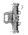
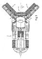
- FIG. 2 shows the transition to the transport position, wherein the central unit 3 is raised so far in a straight-line lifting movement, that the two side units 4, 5 in a pivoting movement about substantially vertical pivot axes 6, 7 (see FIG. 3 ) can be pivoted by means of corresponding actuators, such as working cylinder 8, 9 below the center unit 3 forward in the direction of travel F.
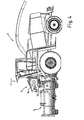
- FIG. 4 shows the transport position, wherein the center unit 3 is fully raised and the side units are pivoted in the direction of travel F forward. In the side view according to FIG. 4 only the side unit 5 is recognizable.
- FIG. 4 is the lifting system 10 with vertical column 11 can be seen, through which the center unit 3 is vertically linearly liftable.
- the center unit 3 is guided with a lifting carriage 12 in the vertical column.
- the lifting member itself is not recognizable, but can be provided in different versions, for example as a lifting cylinder, as a spindle drive, etc.
- the central unit 3 has a lower take-up rotor 13, which can pick up crop lying on the ground in the working position by means of receiving and conveying tines which are not clearly visible and conveys it into the area of action of a transverse screw conveyor 14.
- the side units 4, 5 are constructed accordingly.
- the associated receiving motors 15, 16 and the corresponding transverse screw conveyors 17, 18 clearly visible.
- the take-up motors 13, 15, 16 is lying on the ground crop over the entire working width (see. FIG. 1 ) and then fed by means of the transverse augers 14, 17, 18 a central receiving shaft of the forage harvester 1.
- FIG. 6 shows the drive of the receiving device 2, wherein via a central transfer case 19, the driving force of a motor located in the vehicle of the receiving device 2 is supplied.
- a drive shaft 20 can be connected to a PTO shaft of the vehicle, that is to say the forage harvester 1, for example by means of a conventional PTO shaft.
- a side branch 21, which branches off from the transfer case 19, serves to drive both the conveying rotor and the transverse screw conveyor of the side unit 5.
- variable-length drive shaft 25 Via a transmission gear 24, a variable-length drive shaft 25 is driven, which extends substantially parallel to the drive shaft 22.
- the variable-length propeller shaft 25 is via a transmission gear 26 to drive the receiving motor 13 of the center unit 3. Accordingly, transmission gear 26 and thus the output side end 27 of the variable length propeller shaft 25 in the lifting movement of the center unit 3 in the direction H can be raised.
- the propeller shaft 25 is both transverse to the stroke direction H and transverse to the direction F.
- the arrangement transverse to the stroke direction H can be bridged by the length variability of the propeller shaft 25 between the output side 27 and the drive side 28 of the required stroke.
- FIG. 7 shows the drive train with raised center unit 3.
- the transmission gear 26 for driving the take-up motor 13 of the center unit 3 is hereby raised, while the variable-length propeller shaft 25 is pivoted upwards and pulled out.
- a variant not realized in this embodiment variant could consist in that also the articulated shaft 22 with the transmission gear 24 could be raised with direction H and at the same time length-extendable. This could be bridged over two oppositely oriented drive shafts with a comparatively small length extension a large lifting height. This variant could be expanded to a certain extent zigzag or accordion-like.
- variable length propeller shaft 25 is provided, which is arranged according to the invention transversely to the direction of displacement and also transverse to the direction of travel F, to bridge the straight-line stroke of the central unit 3 with respect to the drive train.
- a propeller shaft 25 is to be selected with a correspondingly large length extension.
- Suitable for use cardan shafts are available, for example, under the trade name Telespace Cardan shaft.
- FIGS. 6 and 7 also recognizable by the drive of the screw conveyor 14.
- a further transmission gear 29 is provided with subsequent bevel gear 30 in front of the transmission gear 24.
- the angle gear 30 forms the drive source for a further arranged above bevel gear 31, to which the propeller shaft 32 is connected for driving the cross auger 14.
- the transverse screw conveyor 14 is otherwise constructed in two parts on both sides of the intake shaft as a screw 14a and 14b and is thus driven via two transmission gear 33a, b.
- a dog clutch 34 is now arranged according to the invention, in accordance with the working position FIG. 6 closed in transport position according to FIG. 7 however, it is solved.
- the two claws 35, 36 solve themselves when lifting in the direction of stroke H easily automatically.
- the claws 35, 36 may also automatically engage independently with appropriate angular orientation.
- the angular position of the claws 35, 36 is irrelevant in a screw drive as shown.
- the claw 36 With twisted angular position, in which the claws do not engage directly, different possibilities are conceivable to close the claw coupling.
- a positive guide for the production of the right angle to engage can as realized in the described embodiment also realized one of the two claws, in this case the claw 36 against a force member slidably.
- the claw 36 can be pressed with its shaft in the spring sleeve 37, wherein the back pressure of a non-illustrated, arranged in the spring sleeve 37 compression spring is overcome. If the jaws 35, 36 are pressed together in a non-latching position, they lock automatically upon actuation of the drive by turning the central drive shaft 20, as soon as the appropriate angular position is reached.
- a translationally displaceable working unit such as the center unit 3 can be connected to a drive train, wherein a large stroke length H L can be bridged.
- the drive shaft 38 for the transmission 31 which is the output shaft of the angular gear 30 in the illustrated embodiment, arranged in the stroke direction H and connected to the dog clutch 34.
- both variants of the invention for connecting a translationally movable working unit are realized.
- This embodiment is particularly advantageous if the drive sources 24, 30 are arranged identically or directly to one another for both variants of the Hubüberbrückung, since in this way starting from the same location a power transmission to spaced-apart positions can be provided.
Landscapes
- Life Sciences & Earth Sciences (AREA)
- Environmental Sciences (AREA)
- Engineering & Computer Science (AREA)
- Mechanical Engineering (AREA)
- Soil Sciences (AREA)
- Agricultural Machines (AREA)
Description
- Die Erfindung betrifft eine landwirtschaftliche Maschine, insbesondere zum Frontanbau an einem landwirtschaftlichen Fahrzeug nach dem Oberbegriff des Anspruchs 1.
- Zum Frontanbau an landwirtschaftlichen Fahrzeugen sind unterschiedliche landwirtschaftliche Maschinen in Gebrauch. Vielfach weisen derartige Maschinen verschiedene Arbeitseinheiten auf, die zwischen einer breiten Arbeitsstellung und einer schmaleren Transportstellung verstellbar ausgebildet sind. Die Druckschrifte
DE 43 22 236 B4 GB 1275492 US 4409780 undFR 2 781 118 - Bei derartigen Maschinen wie dem genannten Stand der Technik wird die zentrale Fronteinheit mittels einer üblicherweise an landwirtschaftlichen Fahrzeugen vorgesehenen Fronthydraulik angehoben und die Seiteneinheiten um eine oder mehrere Schwenkachsen in die Transportstellung eingeschwenkt. Bei Schwenkbewegungen, wie z.B. die beim Anheben der Frontarbeitseinheit, ist der Antriebsschluss über eine Gelenkwelle und ein oder mehrere Verteilergetriebe unproblematisch, da die Gelenkwelle im Wesentlichen die Schwenkbewegungen der entsprechenden Schwinge ohne nennenswerte Längenänderung durchführen kann.
- Bei Arbeitseinheiten, die gegenüber ihrer Antriebsquelle einer translatorischen Bewegung, dass heißt einer Verschiebung unterliegen, ist dies in herkömmlicher Weise nicht möglich. Bei einer üblicherweise vorgesehenen Gelenkwelle, die sich von der Antriebsquelle direkt zur Arbeitseinheit hin in Fahrtrichtung erstreckt, müsste die Gelenkwelle den kompletten Versatz der Arbeitseinheit Längenvariabel ausgleichen können. Dies ist bei entsprechend großen Relativbewegungen und vor allem bei dicht am Fahrzeug angebrachten Arbeitseinheiten, die in Fahrtrichtung nur sehr kurze Gelenkwellen zulassen nicht möglich.
- Aufgabe der Erfindung ist es dementsprechend, eine landwirtschaftliche Maschine vorzuschlagen, bei der dieser Nachteil behoben ist.
- Diese Aufgabe wird durch die Merkmale des Anspruchs 1 gelöst.
- Durch die in den Unteransprüche genannten Maßnahmen sind vorteilhafte Ausführungen und Weiterbildungen der Erfindung möglich.
- Dementsprechend zeichnet sich eine erfindungsgemäße Ausführung einer landwirtschaftliche Maschine durch eine quer zur Verschieberichtung und quer zur vorgesehenen Fahrtrichtung angeordnete längenvariable Gelenkwelle aus.
- Durch diese Maßnahme kann eine Verschiebebewegung der Arbeitseinheit realisiert werden, wobei der Antrieb über eine Gelenkwelle geschlossen werden kann. Die Queranordnung der Gelenkwelle bezüglich der Fahrtrichtung ermöglicht die Verwendung einer erheblich längeren Gelenkwelle, als dies bei einem direkten Kraftschluss zwischen Arbeitseinheit und Antriebsquelle in Verschiebrichtung möglich wäre. Durch die Anordnung quer zur Verschieberichtung wird verhindert, dass die Gelenkwelle in Verschiebrichtung nur teleskopartig angezogen wird. Vielmehr folgt die Längenänderung der quer zur Verschiebrichtung angeordneten Gelenkwelle bei der Verschiebebewegung der Arbeitseinheit einer Winkelfunktion so das die erforderliche relative Längenänderung, d.h. das Längenverhältnis bei ausgezogener Gelenkwelle und eingefahrener Gelenkwelle deutlich kleiner gehalten werden kann.
- Diese Vorteile sind bereits bei einer Queranordnung der Gelenkwelle zu erzielen, bei der die Gelenkwelle nur schräg, d.h. unter einem Winkel kleiner 90° zur verschieberichtung der Arbeitseinheit angeordnet ist. Besonders vorteilhaft kommt die Wirkung jedoch dann zum Tragen, wenn in der Ausgangsstellung die Gelenkwelle soweit als möglich rechtwinklig zur Verschieberichtung bzw. nahezu parallel zur Arbeitseinheit steht.
- Weiterhin ist es von Vorteil, eine möglichst lange Gelenkwelle bereits im eingefahrenen Zustand zu verwenden, da hierdurch große Verschiebewege der Arbeitseinheit bei vergleichsweise kleiner relativen Längenänderung der Gelenkwelle realisierbar sind. Die Gelenkwelle schwenkt dabei während der Verschiebung der Arbeitseinheit um ihren endseitigen Ruhepunkt, während sie ausgefahren wird. Eine möglichst lange Gelenkwelle lässt sich beispielsweise dadurch erzielen, dass die Antriebsquelle auf einer Seite der Mittelachse der Arbeitseinheit angebracht ist und sich die Gelenkwelle auf die andere Seite hin der Mittelachse bezogen auf die Verschieberichtung erstreckt.
- Bei Arbeitseinheiten, die als Frontarbeitseinheit vor einem landwirtschaftlichen Fahrzeug angebracht sind, entspricht die Arbeitsbreite derartiger Arbeitseinheiten in der Regel der Transportbreite und häufig auch der Breite des zugehörigen Fahrzeugs, so dass die maximale Transport- und Arbeitsbreite genutzt wird. Bei einer solchen Arbeitseinheit wird dementsprechend die zugehörige Gelenkwelle quer zur Fahrtrichtung und sich über die Mittelachse des zugehörigen Fahrzeugs erstreckend angeordnet.
- Die erfindungsgemäßen Vorteile lassen sich weiter steigern, indem eine zweite, an die erste Gelenkwelle gekoppelte Gelenkwelle vorgesehen ist, die sich von der Abtriebsseite der ersten Gelenkwelle zur Antriebsquelle zurück erstreckt. Es ergibt sich somit gewissermaßen eine Zickzackanordnung bzw. eine gefaltete Anordnung zweier Gelenkwellen. Dies kann zum Einen dazu verwendet werden, um für die zweite Gelenkwelle einen optimalen Ausgangspunkt, z.B. weit von der Mittelachse der Arbeitseinheit entfernt, zu finden und die zweite Gelenkwelle mit größerer Länge ausbilden zu können.
- Ein anderer Vorteil bei einer solchen Anordnung ergibt sich dann, wenn der Anschlusspunkt der beiden Gelenkwellen in Verschieberichtung mitwandern kann. In diesem Fall kann in einer Art Ziehharmonikaeffekt die Längenvariabilität beider Gelenkwellen für die Verschiebebewegung der Arbeitseinheit genutzt werden.
- Vorzugsweise werden zwei derartige Gelenkwellen über ein Getriebe gekoppelt. Ein solches Getriebe kann fest montiert sein oder aber zur Erzielung eines Ziehharmonikaeffekts wie oben beschrieben in Verschieberichtung der Arbeitseinheit verschieblich sein, wozu in diesem Fall entsprechende Führungselemente oder dergleichen je nach Bedarf vorzusehen sind.
- Die Erfindung ist besonders vorteilhaft bei einer landwirtschaftlichen Maschine einsetzbar, bei der eine linear hubfähige Arbeitseinheit vorgesehen ist. Wie bereits eingangs erwähnt werden hubfähige Arbeitseinheiten bei landwirtschaftlichen Maschinen in der Regel über Schwingen des entsprechenden landwirtschaftlichen Fahrzeugs in einer Schwenkbewegung um eine horizontale Schwenkachse angehoben bzw. abgesenkt. In diesem Fall ist es aufgrund der gleichbleibenden Länge der Schwinge relativ problemlos, den Antrieb über eine in Richtung einer solchen Schwinge sich erstreckende Gelenkwelle herzustellen. Erfindungsgemäß kann jedoch nunmehr auch eine linear hubfähige Arbeitseinheit antriebsmäßig angeschlossen werden, die über ein entsprechendes Hubsystem verfügt. Die hubfähige Arbeitseinheit wird bei einer solchen Maschine gewissermaßen in einer Art Lift vor dem Fahrzeug angehoben. Eine solche Anordnung hat den Vorteil dass die Arbeitseinheit sehr nahe am landwirtschaftlichen Fahrzeug angeordnet werden kann.
- Eine derartige Maschine bietet insbesondere als Erntemaschine entsprechende Vorteile, beispielsweise als Mähmaschine oder Maschine zum Aufnehmen von am Boden liegenden Erntegut.
- Neben der vorbeschriebenen Lösung der oben genannten Aufgabe wird erfindungsgemäß noch ein zweiter Weg dahingehend vorgeschlagen, dass die Antriebsquelle eine in die Verschieberichtung gerichtete Antriebswelle aufweist und eine lösbare Kupplung zwischen der Arbeitseinheit und der Antriebsquelle vorgesehen ist.
- Diese Lösung kann dann verwendet werden, wenn die Arbeitsstellung bei geschlossener Kupplung, dass heißt bei minimalem Abstand zwischen Arbeitseinheit und Antriebsquelle vorliegt und die Transportstellung in weggeschobenem beispielsweise angehobenem Zustand der Arbeitseinheit gegeben ist. Die Verwendung einer lösbaren Kupplung bietet den Vorteil, dass ein sehr kompakter Antriebsstrang zwischen Antriebsquelle und Arbeitseinheit vorliegt und dabei ein sehr großer Verschiebeweg, beispielsweise ein sehr großer Hub ohne Probleme beim Antriebschluss möglich ist.
- Zur Realisierung einer solchen lösbaren Erfindung wird vorzugsweise eine Klauenkupplung verwendet, die einen zuverlässigen verschleißfreien Kraftschluss bietet, leicht lösbar und wieder schließbar ist und darüber hinaus je nach Anordnung auch noch die Möglichkeit einer definierten Winkelstellung zwischen An- und Abtriebswelle der Kupplung bietet.
- Die Möglichkeit, die Winkelstellung definiert vorzugeben ist je nach Anwendungsfall bei einer lösbaren Kupplung von besonderer Bedeutung, um die daran angeschlossenen Arbeitswerkzeuge synchron und in definierter Phasenlage zu betreiben. Eine solche definierte Winkellage beim Schließen der Kupplung herzustellen ist somit auch bei erfindungsgemäßer Verwendung anderweitiger lösbarer Kupplungen von Vorteil.
- Vorzugsweise wird die lösbare Kupplung so ausgebildet, dass die Verschiebebewegung der Arbeitseinheit selbsttätig lösbar und/oder selbsttätig schließbar ist. Hierdurch erübrigt sich eine entsprechende Betätigungsvorrichtung bzw. eine entsprechende Steuervorrichtung. Eine selbsttätig arbeitende Kupplung kann beispielsweise wiederum durch eine Klauenkupplung verwirklicht werden, die problemlos selbsttätig zu öffnen ist und beim Schließen durch ein Kraftelement, beispielsweise eine Druckfeder druckbeaufschlagt wird, so dass sie beim Drehen der Antriebswelle einrastet.
- Selbstverständlich kann eine solche lösbare Kupplung auch ansteuerbar ausgebildet sein, was je nach Anwendungsfall wiederum Vorteile bilden kann. So kann beispielsweise über eine ansteuerbare Kupplung die angeschlossene Arbeitseinheit separat gesteuert, insbesondere auch separat gestartet und gestoppt werden.
- Ein Ausführungsbeispiel der Erfindung ist in der Zeichnung dargestellt und wird anhand der Erfindung der Figuren nachfolgend näher erläutert.
- Im Einzelnen zeigen
- Figur 1
- eine Frontansicht eines sogenannten Feldhäckslers mit dreiteiliger Aufnahmevorrichtung in Arbeitsstellung,
- Figur 2
- eine Frontansicht eines Feldhäckslers gemäß
Figur 1 in einer Übergangsstellung in der Aufnahmevorrichtung für einen Übergang in die Transportstellung, - Figur 3
- eine Draufsicht von oben auf einen Feldhäcksler in der Übergangsstellung gemäß
Figur 2 , - Figur 4
- eine Seitenansicht auf einen Feldhäcksler mit dreiteiliger Aufnahmevorrichtung in Transportstellung,
- Figur 5
- eine Frontansicht auf einen Feldhäcksler gemäß
Figur 4 in Transportstellung, - Figur 6
- eine perspektivische Darstellung des Antriebs für die dreiteilige Aufnahmevorrichtung in Arbeitsstellung und
- Figur 7
- eine perspektivische schematische Darstellung des Antriebsstrangs für eine dreiteilige Aufnahmevorrichtung in Transportstellung.
- Die Erfindung wird anhand der Figuren anhand eines Feldhäckslers 1 beschrieben, der eine dreiteilige Aufnahmevorrichtung 2 im Frontanbau trägt. Derartige Aufnahmevorrichtungen 2 werden regelmäßig in Fachkreisen als sogenannte Pick-Up bezeichnet.
- Die dargestellte Aufnahmevorrichtung 2 besteht aus einer linear hubfähigen zentralen Mitteleinheit 3 und zwei schwenkbaren Seiteneinheiten 4, 5. Die hubfähige Mitteleinheit 3 stellt somit eine erfindungsgemäße durch translatorische oder lineare Verschiebung verschiebbare d.h. anhebbare Arbeitseinheit dar.
-
Figur 2 zeigt den Übergang in die Transportstellung, wobei die Mitteleinheit 3 so weit in einer gradlinigen Hubbewegung angehoben ist, dass die beiden Seiteneinheiten 4, 5 in einer Schwenkbewegung um im Wesentlichen vertikal stehende Schwenkachsen 6, 7 (vergleicheFigur 3 ) mittels entsprechender Stellorgane, beispielsweise Arbeitszylinder 8, 9 unterhalb der Mitteleinheit 3 nach vorne in Fahrtrichtung F verschwenkt werden können.Figur 4 zeigt die Transportstellung, wobei die Mitteleinheit 3 vollständig angehoben ist und die Seiteneinheiten in Fahrtrichtung F nach vorne geschwenkt sind. In der Seitenansicht gemäßFigur 4 ist dabei nur die Seiteneinheit 5 erkennbar. - In
Figur 4 ist das Hubsystem 10 mit Vertikalsäule 11 erkennbar, durch das die Mitteleinheit 3 vertikal linear anhebbar ist. Die Mitteleinheit 3 ist mit einem Hubschlitten 12 in der Vertikalsäule geführt. Das Huborgan selbst ist nicht erkennbar, kann jedoch in unterschiedlicher Ausführung vorgesehen werden, beispielsweise als Hubzylinder, als Spindelantrieb, usw. - In
Figur 4 ist weiterhin erkennbar, dass die Mitteleinheit 3 einen unteren Aufnahmerotor 13 aufweist, der mittels nicht näher erkennbarer Aufnahme- und Förderzinken in Arbeitsstellung am Boden liegendes Erntegut aufnehmen kann und dieses in den Wirkungsbereich einer Querförderschnecke 14 fördert. - Die Seiteneinheiten 4, 5 sind entsprechend aufgebaut. In
Figur 5 sind die zugehörigen Aufnahmerotoren 15, 16 sowie die entsprechenden Querförderschnecken 17, 18 gut erkennbar. Mittels der Aufnahmerotoren 13, 15, 16 wird am Boden liegendes Erntegut über die gesamte Arbeitsbreite (vgl.Figur 1 ) aufgenommen und anschließend mittels der Querförderschnecken 14, 17, 18 einem zentralen Aufnahmeschacht des Feldhäckslers 1 zugeführt. -
Figur 6 zeigt den Antrieb der Aufnahmevorrichtung 2, wobei über ein zentrales Verteilergetriebe 19 die Antriebskraft eines im Fahrzeug befindlichen Motors der Aufnahmevorrichtung 2 zugeführt wird. Eine Antriebswelle 20 kann hierzu beispielsweise mittels einer üblichen Gelenkwelle mit einer Zapfwelle des Fahrzeugs, dass heißt des Feldhäckslers 1 verbunden werden. - Ein Seitenstrang 21, der vom Verteilergetriebe 19 abzweigt, dient dazu, sowohl den Förderrotor als auch die Querförderschnecke der Seiteneinheit 5 anzutreiben.
- In die andere Richtung zweigt vom Verteilergetriebe 19 eine Gelenkwelle 22 ab, über die unter anderem der rechte Seitenstrang 23 für den Antrieb der rechten Seiteneinheit 4 mit Aufnahmerotor und Querförderschnecke angetrieben wird.
- Über ein Transmissionsgetriebe 24 wird eine längenvariable Gelenkwelle 25 angetrieben, die im Wesentlichen parallel zur Gelenkwelle 22 verläuft. Die längenvariable Gelenkwelle 25 dient über ein Transmissionsgetriebe 26 dem Antrieb des Aufnahmerotors 13 der Mitteleinheit 3. Dementsprechend ist Transmissionsgetriebe 26 und somit auch das abtriebsseitige Ende 27 der längenvariablen Gelenkwelle 25 in der Hubbewegung der Mitteleinheit 3 in Richtung H anhebbar.
- Ersichtlich liegt die Gelenkwelle 25 sowohl quer zur Hubrichtung H als auch quer zur Fahrtrichtung F.
- Durch die Anordnung quer zur Hubrichtung H kann zwischen der Abtriebsseite 27 und der Antriebsseite 28 der erforderliche Hub durch Längenvariabilität der Gelenkwelle 25 überbrückt werden. Durch die Anordnung quer zur Fahrtrichtung F ist dabei zugleich eine Position der Mitteleinheit 3 in unmittelbarer Nähe zu dem Verteilergetriebe 19 bzw. dem Transmissionsgetriebe 24 im querverlaufenden Antriebsstrang möglich.
-
Figur 7 zeigt den Antriebsstrang bei angehobener Mitteleinheit 3. Das Transmissionsgetriebe 26 für den Antrieb des Aufnahmerotors 13 der Mitteleinheit 3 ist hierbei angehoben, während die längenvariable Gelenkwelle 25 nach oben geschwenkt und ausgezogen ist. - Eine in dieser Ausführungsvariante nicht realisierte Variante könnte darin bestehen, dass auch die Gelenkwelle 22 mit dem Transmissionsgetriebe 24 nach oben mit Richtung H anhebbar und zugleich längenausziehbar wäre. Hierdurch könnte über zwei gegensinnig ausgerichtete Gelenkwellen mit vergleichsweise geringen Längenauszug eine große Hubhöhe überbrückt werden. Diese Variante könnte gewissermaßen zickzackförmig oder ziehharmonikaförmig weiter ausgebaut werden.
- Im vorliegenden Ausführungsbeispiel ist jedoch nur eine längenvariable Gelenkwelle 25 vorgesehen, die erfindungsgemäß quer zur verschieberichtung und zudem quer zur Fahrtrichtung F angeordnet ist, um den gradlinigen Hub der Mitteleinheit 3 gegenüber dem Antriebsstrang zu überbrücken.
- In diesem Fall ist eine Gelenkwelle 25 mit entsprechend großen Längenauszug zu wählen. Dafür verwendbare Gelenkwellen sind beispielsweise unter dem Handelsnamen Telespace-Gelenkwelle erhältlich.
- Die zweite erfindungsgemäße Variante, den Antrieb einer translatorisch verstellbaren Arbeitseinheit in der beschriebenen Ausführung der Aufnahmevorrichtung 2 mit der Mitteleinheit 3 zu realisieren, ist in
Figuren 6 und7 anhand des Antriebs der Förderschnecke 14 ebenfalls erkennbar. Hierzu ist vor dem Transmissionsgetriebe 24 ein weiteres Transmissionsgetriebe 29 mit anschließendem Winkelgetriebe 30 vorgesehen. Das Winkelgetriebe 30 bildet dabei die Antriebsquelle für ein darüber angeordnetes weiteres Winkelgetriebe 31, an das die Gelenkwelle 32 für den Antrieb der Querförderschnecke 14 angeschlossen ist. - Die Querförderschnecke 14 ist im übrigen zweiteilig beidseitig des Einzugsschachts als Schnecke 14a und 14b aufgebaut und wird somit über zwei Transmissionsgetriebe 33a, b angetrieben.
- Zwischen der Antriebsquelle 30 und dem Antrieb 31 der Querförderschnecke 14 ist nunmehr erfindungsgemäß eine Klauenkupplung 34 angeordnet, die in Arbeitsstellung gemäß
Figur 6 geschlossen in Transportstellung gemäßFigur 7 jedoch gelöst ist. Die beiden Klauen 35, 36 lösen sich beim Anheben in Hubrichtung H problemlos selbsttätig. Beim Schließen der Klauenkupplung 34 können bei entsprechender Winkelorientierung die Klauen 35, 36 unter Umständen ebenfalls problemlos selbstständig ineinander rasten. Die Winkellage der Klauen 35, 36 ist bei einem Schneckenantrieb wie dargestellt ohne Bedeutung. - Bei verdrehter Winkelstellung, in der die Klauen nicht direkt einrasten, sind unterschiedliche Möglichkeiten denkbar, die Klauenkupplung zu schließen. Neben einer Zwangsführung zur Herstellung der zum Einrasten richtigen Winkelorientierung kann wie im beschriebenem Ausführungsbeispiel realisiert auch eine der beiden Klauen, vorliegend die Klaue 36 gegen ein Kraftglied verschiebbar ausgebildet sein. Vorliegend kann beispielsweise die Klaue 36 mit ihrem Schaft in die Federhülse 37 eingedrückt werden, wobei der Gegendruck einer nicht näher dargestellten, in der Federhülse 37 angeordneten Druckfeder zu überwinden ist. Sofern die Klauen 35, 36 in nicht rastender Stellung aufeinandergedrückt werden, rasten diese bei Betätigung des Antriebs durch Drehen der zentralen Antriebswelle 20 selbsttätig ein, sobald die passende Winkelstellung erreicht ist.
- Über eine derartige Klauenkupplung 34 kann eine translatorisch verschiebbare Arbeitseinheit wie die Mitteleinheit 3 an einem Antriebsstrang angeschlossen werden, wobei eine große Hublänge HL überbrückbar ist. Hierbei wird die Antriebswelle 38 für das Getriebe 31, die im dargestellten Ausführungsbeispiel die Abtriebswelle des Winkelgetriebes 30 ist, in Hubrichtung H angeordnet und an die Klauenkupplung 34 angeschlossen.
- In der dargestellten Ausführungsvariante einer landwirtschaftlichen Maschine in Form der Aufnahmevorrichtung 2 sind somit beide erfindungsgemäßen Varianten zum Anschluss einer translatorisch bewegbaren Arbeitseinheit realisiert. Diese Ausführung ist besonders vorteilhaft, wenn die Antriebsquellen 24, 30 für beide Varianten der Hubüberbrückung identisch oder unmittelbar beieinander angeordnet sind, da auf dieser Weise ausgehend vom gleichem Ort eine Kraftübertragung zu voneinander beabstandeten Positionen vorgesehen werden kann.
-
- 1
- Feldhäcksler
- 2
- Aufnahmevorrichtung
- 3
- Mitteleinheit
- 4
- Seiteneinheit
- 5
- Seiteneinheit
- 6
- Schwenkachse
- 7
- Schwenkachse
- 8
- Arbeitszylinder
- 9
- Arbeitszylinder
- 10
- Hubsystem
- 11
- Vertikalsäule
- 12
- Hubschlitten
- 13
- Aufnahmerotor
- 14
- Querförderschnecke
- 15
- Aufnahmerotor
- 16
- Aufnahmerotor
- 17
- Querförderschnecke
- 18
- Querförderschnecke
- 19
- Verteilergetriebe
- 20
- Antriebswelle
- 21
- Seitenstrang
- 22
- Gelenkwelle
- 23
- Seitenstrang
- 24
- Transmissionsgetriebe
- 25
- längenvariable Gelenkwelle
- 26
- Transmissionsgetriebe
- 27
- Abtriebsseite
- 28
- Antriebsseite
- 29
- Transmissionsgetriebe
- 30
- Winkelgetriebe
- 31
- Winkelgetriebe
- 32
- Gelenkwelle
- 33
- Transmissionsgetriebe
- 34
- Klauenkupplung
- 35
- Klaue
- 36
- Klaue
- 37
- Federhülse
- 38
- Antriebswelle
Claims (16)
- Landwirtschaftliche Maschine, insbesondere zum Frontanbau an ein landwirtschaftliches Fahrzeug, mit wenigstens einer Arbeitseinheit (2, 3), die gegenüber einer Antriebsquelle (30) verschiebbar ist, dadurch gekennzeichnet, dass die verschiebbare Arbeitseinheit (2, 3) durch translatorische oder lineare Bewegung zwischen einer Transportstellung und einer Arbeitsstellung verschiebbar und als linear hubfähige, zentrale Mitteleinheit (3) ausgebildet ist, wobei zwei schwenkbare Seiteneinheiten (4, 5) vorgesehen sind, und dass zum Überbrücken der translatorischen oder linearen Bewegung der Arbeitseinheit (2, 3) zwischen einer Transportstellung und einer Arbeitsstellung einerseits die Antriebsquelle (30) eine Antriebswelle (38) in Verschieberichtung (H) der Arbeitseinheit (2, 3) aufweist sowie eine lösbare Kupplung (34) zwischen Arbeitseinheit (2, 3) und Antriebsquelle (30) vorgesehen ist und andererseits eine quer zur vorgesehenen Fahrtrichtung (F) angeordnete, längenvariable Gelenkwelle (25) vorgesehen ist.
- Maschine nach Anspruch 1, dadurch gekennzeichnet, dass die Antriebsquelle seitlich der Mittelachse der Antriebseinheit (24) vorgesehen ist und sich die Gelenkwelle (25) auf die der Antriebsquelle (24) gegenüberliegenden Seite der Mittelachse erstreckt.
- Maschine nach einem der vorgenannten Ansprüche, dadurch gekennzeichnet, dass eine zweite, die erste Gelenkwelle gekoppelte Gelenkwelle vorgesehen ist, die sich zur Seite der Antriebsquelle zurück erstreckt.
- Maschine nach einem der vorgenannten Ansprüche dadurch gekennzeichnet, dass beide Gelenkwellen über ein Getrieb gekoppelt sind.
- Maschine nach einem der vorgenannten Ansprüche dadurch gekennzeichnet, dass das Getriebe während der Verschiebung der Arbeitseinheit verschiebbar ist.
- Maschine nach einem der vorgenannten Ansprüche dadurch gekennzeichnet, dass die Arbeitseinheit (2) hubfähig ist.
- Maschine nach einem der vorgenannten Ansprüche dadurch gekennzeichnet, dass die Maschine eine Erntemaschine ist.
- Maschine nach einem der vorgenannten Ansprüche dadurch gekennzeichnet, dass die Maschine eine Aufnahmevorrichtung (2) für am Boden liegendes Erntegut ist.
- Maschine nach einem der vorgenannten Ansprüche, dadurch gekennzeichnet, dass die verschiebbare Arbeitseinheit (2) eine linear hubfähige, zentrale Fronteinheit ist.
- Maschine nach Anspruch 1, dadurch gekennzeichnet, dass die lösbare Kupplung eine Klauenkupplung (34) ist.
- Maschine nach einem der Ansprüche 1 oder 10, dadurch gekennzeichnet, dass die Kupplung (34) selbsttätig mit der Verschiebebewegung (H) der Arbeitseinheit (2) lösbar und/oder schließbar ist.
- Maschine nach einem der Ansprüche 1 bis 11, dadurch gekennzeichnet, dass die lösbare Kupplung (34) ansteuerbar betätigbar ist.
- Maschine nach einem der Ansprüche 1 bis 12, dadurch gekennzeichnet, dass die Arbeitseinheit (2) hubfähig ist.
- Maschine nach einem der vorgenannten Ansprüche 1 bis 13, dadurch gekennzeichnet, dass die Maschine eine Erntemaschine ist.
- Maschine nach einem der Ansprüche 1 bis 14, dadurch gekennzeichnet, dass die Maschine eine Aufnahmevorrichtung (2) für am Boden liegendes Erntegut ist.
- Maschine nach einem der Ansprüche 1 bis 15, dadurch gekennzeichnet, dass die verschiebbare Arbeitseinheit (2) eine linear hubfähige, zentrale Fronteinheit ist.
Applications Claiming Priority (1)
| Application Number | Priority Date | Filing Date | Title |
|---|---|---|---|
| DE200610059842 DE102006059842A1 (de) | 2006-12-15 | 2006-12-15 | Landwirtschaftliche Maschine |
Publications (3)
| Publication Number | Publication Date |
|---|---|
| EP1932412A2 EP1932412A2 (de) | 2008-06-18 |
| EP1932412A3 EP1932412A3 (de) | 2008-09-03 |
| EP1932412B1 true EP1932412B1 (de) | 2013-09-25 |
Family
ID=39186075
Family Applications (1)
| Application Number | Title | Priority Date | Filing Date |
|---|---|---|---|
| EP20070023390 Not-in-force EP1932412B1 (de) | 2006-12-15 | 2007-12-04 | Landwirtschaftliche Maschine |
Country Status (2)
| Country | Link |
|---|---|
| EP (1) | EP1932412B1 (de) |
| DE (1) | DE102006059842A1 (de) |
Families Citing this family (1)
| Publication number | Priority date | Publication date | Assignee | Title |
|---|---|---|---|---|
| DE102012020994B4 (de) | 2012-10-26 | 2023-12-21 | Claas Saulgau Gmbh | Landwirtschaftliches Fahrzeug |
Family Cites Families (7)
| Publication number | Priority date | Publication date | Assignee | Title |
|---|---|---|---|---|
| BE733926A (de) * | 1969-06-02 | 1969-12-02 | ||
| US4409780A (en) * | 1982-03-11 | 1983-10-18 | Kansas State University Research Foundation | Folding header assembly |
| DE4106811A1 (de) * | 1991-03-04 | 1992-09-10 | Claas Saulgau Gmbh | Kreiselmaehwerk |
| DE4322236C2 (de) | 1993-07-03 | 1995-11-23 | Wicona Bausysteme Gmbh | Vorrichtung zur Verbindung von vorzugsweise aus Metall bestehenden Hohlprofilen |
| FR2781118B1 (fr) * | 1998-07-16 | 2000-09-08 | Bmv | Equipement d'ensileuse |
| IT1315102B1 (it) * | 2000-06-30 | 2003-02-03 | Cressoni Spa Flli | Apparecchiatura barra di taglio per macchine agricole di raccolta |
| DE10302692B4 (de) * | 2003-01-24 | 2019-03-07 | Maschinenfabrik Kemper Gmbh & Co. Kg | Antriebssystem für einen Erntevorsatz einer Erntemaschine |
-
2006
- 2006-12-15 DE DE200610059842 patent/DE102006059842A1/de not_active Withdrawn
-
2007
- 2007-12-04 EP EP20070023390 patent/EP1932412B1/de not_active Not-in-force
Also Published As
| Publication number | Publication date |
|---|---|
| EP1932412A2 (de) | 2008-06-18 |
| EP1932412A3 (de) | 2008-09-03 |
| DE102006059842A1 (de) | 2008-06-19 |
Similar Documents
| Publication | Publication Date | Title |
|---|---|---|
| DE69312343T2 (de) | Mähmaschine mit einer verbesserten Verriegelungsvorrichtung | |
| EP0792574B1 (de) | Gezogenes Gerät | |
| DE3628605C2 (de) | ||
| EP0771522B1 (de) | Ballenpresse | |
| DE2111227A1 (de) | Maehdrescher | |
| EP0317767B1 (de) | Scheibenwischeranordnung | |
| EP1932412B1 (de) | Landwirtschaftliche Maschine | |
| DE69604845T2 (de) | Vorrichtung mit einem zurückziehbaren Haken für das Abschleppen von Fahrzeugen | |
| EP1378160B1 (de) | Mäh- und Fördereinrichtung für stängeliges Erntegut | |
| EP0823342B1 (de) | Anhängerkupplung | |
| DE3926381C1 (en) | Agricultural machine drive system - incorporates clutch with operating element connected to swivelling outer frame parts | |
| DE202006018874U1 (de) | Landwirtschaftliche Maschine | |
| EP1665922A1 (de) | Heuwerbungsmaschine | |
| DE102006059220A1 (de) | Mähmaschine zur frontseitigen Anordnung an einem landwirtschaftlichen Fahrzeug | |
| DE202007006589U1 (de) | Motorschloss mit Mehrpunktverriegelung | |
| EP4278877B1 (de) | Landwirtschaftliches arbeitsgerät zum anbauen oder anhängen an ein zugfahrzeug und verfahren zum einrichten eines strassenbetriebs eines landwirtschaftlichen arbeitsgeräts | |
| EP1597953B1 (de) | Landwirtschaftliche Maschine | |
| AT412698B (de) | Heuwerbungsmaschine | |
| DE69705346T2 (de) | Mähmaschine | |
| DE102005061405B4 (de) | Heuwerbungsmaschine | |
| DE1236261B (de) | Regelhydraulik fuer den Kraftheber eines Ackerschleppers | |
| AT7640U1 (de) | Schwadkreisel | |
| DE69914151T2 (de) | Landmaschine | |
| DE102006008547B3 (de) | Schneeschleudervorrichtung zum Anbau an ein Fahrzeug | |
| DE102016108032B4 (de) | Kreiselegge |
Legal Events
| Date | Code | Title | Description |
|---|---|---|---|
| PUAI | Public reference made under article 153(3) epc to a published international application that has entered the european phase |
Free format text: ORIGINAL CODE: 0009012 |
|
| AK | Designated contracting states |
Kind code of ref document: A2 Designated state(s): AT BE BG CH CY CZ DE DK EE ES FI FR GB GR HU IE IS IT LI LT LU LV MC MT NL PL PT RO SE SI SK TR |
|
| AX | Request for extension of the european patent |
Extension state: AL BA HR MK RS |
|
| PUAL | Search report despatched |
Free format text: ORIGINAL CODE: 0009013 |
|
| AK | Designated contracting states |
Kind code of ref document: A3 Designated state(s): AT BE BG CH CY CZ DE DK EE ES FI FR GB GR HU IE IS IT LI LT LU LV MC MT NL PL PT RO SE SI SK TR |
|
| AX | Request for extension of the european patent |
Extension state: AL BA HR MK RS |
|
| 17P | Request for examination filed |
Effective date: 20081223 |
|
| 17Q | First examination report despatched |
Effective date: 20090202 |
|
| AKX | Designation fees paid |
Designated state(s): AT BE BG CH CY CZ DE DK EE ES FI FR GB GR HU IE IS IT LI LT LU LV MC MT NL PL PT RO SE SI SK TR |
|
| GRAJ | Information related to disapproval of communication of intention to grant by the applicant or resumption of examination proceedings by the epo deleted |
Free format text: ORIGINAL CODE: EPIDOSDIGR1 |
|
| GRAP | Despatch of communication of intention to grant a patent |
Free format text: ORIGINAL CODE: EPIDOSNIGR1 |
|
| GRAP | Despatch of communication of intention to grant a patent |
Free format text: ORIGINAL CODE: EPIDOSNIGR1 |
|
| GRAS | Grant fee paid |
Free format text: ORIGINAL CODE: EPIDOSNIGR3 |
|
| GRAA | (expected) grant |
Free format text: ORIGINAL CODE: 0009210 |
|
| INTG | Intention to grant announced |
Effective date: 20130731 |
|
| AK | Designated contracting states |
Kind code of ref document: B1 Designated state(s): AT BE BG CH CY CZ DE DK EE ES FI FR GB GR HU IE IS IT LI LT LU LV MC MT NL PL PT RO SE SI SK TR |
|
| REG | Reference to a national code |
Ref country code: GB Ref legal event code: FG4D Free format text: NOT ENGLISH |
|
| REG | Reference to a national code |
Ref country code: CH Ref legal event code: EP |
|
| REG | Reference to a national code |
Ref country code: AT Ref legal event code: REF Ref document number: 633363 Country of ref document: AT Kind code of ref document: T Effective date: 20131015 |
|
| REG | Reference to a national code |
Ref country code: IE Ref legal event code: FG4D Free format text: LANGUAGE OF EP DOCUMENT: GERMAN |
|
| REG | Reference to a national code |
Ref country code: DE Ref legal event code: R096 Ref document number: 502007012322 Country of ref document: DE Effective date: 20131121 |
|
| PG25 | Lapsed in a contracting state [announced via postgrant information from national office to epo] |
Ref country code: LT Free format text: LAPSE BECAUSE OF FAILURE TO SUBMIT A TRANSLATION OF THE DESCRIPTION OR TO PAY THE FEE WITHIN THE PRESCRIBED TIME-LIMIT Effective date: 20130925 Ref country code: SE Free format text: LAPSE BECAUSE OF FAILURE TO SUBMIT A TRANSLATION OF THE DESCRIPTION OR TO PAY THE FEE WITHIN THE PRESCRIBED TIME-LIMIT Effective date: 20130925 |
|
| REG | Reference to a national code |
Ref country code: NL Ref legal event code: VDEP Effective date: 20130925 |
|
| REG | Reference to a national code |
Ref country code: LT Ref legal event code: MG4D |
|
| PG25 | Lapsed in a contracting state [announced via postgrant information from national office to epo] |
Ref country code: FI Free format text: LAPSE BECAUSE OF FAILURE TO SUBMIT A TRANSLATION OF THE DESCRIPTION OR TO PAY THE FEE WITHIN THE PRESCRIBED TIME-LIMIT Effective date: 20130925 Ref country code: GR Free format text: LAPSE BECAUSE OF FAILURE TO SUBMIT A TRANSLATION OF THE DESCRIPTION OR TO PAY THE FEE WITHIN THE PRESCRIBED TIME-LIMIT Effective date: 20131226 Ref country code: LV Free format text: LAPSE BECAUSE OF FAILURE TO SUBMIT A TRANSLATION OF THE DESCRIPTION OR TO PAY THE FEE WITHIN THE PRESCRIBED TIME-LIMIT Effective date: 20130925 Ref country code: SI Free format text: LAPSE BECAUSE OF FAILURE TO SUBMIT A TRANSLATION OF THE DESCRIPTION OR TO PAY THE FEE WITHIN THE PRESCRIBED TIME-LIMIT Effective date: 20130925 |
|
| PG25 | Lapsed in a contracting state [announced via postgrant information from national office to epo] |
Ref country code: RO Free format text: LAPSE BECAUSE OF FAILURE TO SUBMIT A TRANSLATION OF THE DESCRIPTION OR TO PAY THE FEE WITHIN THE PRESCRIBED TIME-LIMIT Effective date: 20130925 Ref country code: SK Free format text: LAPSE BECAUSE OF FAILURE TO SUBMIT A TRANSLATION OF THE DESCRIPTION OR TO PAY THE FEE WITHIN THE PRESCRIBED TIME-LIMIT Effective date: 20130925 Ref country code: EE Free format text: LAPSE BECAUSE OF FAILURE TO SUBMIT A TRANSLATION OF THE DESCRIPTION OR TO PAY THE FEE WITHIN THE PRESCRIBED TIME-LIMIT Effective date: 20130925 Ref country code: IS Free format text: LAPSE BECAUSE OF FAILURE TO SUBMIT A TRANSLATION OF THE DESCRIPTION OR TO PAY THE FEE WITHIN THE PRESCRIBED TIME-LIMIT Effective date: 20140125 Ref country code: NL Free format text: LAPSE BECAUSE OF FAILURE TO SUBMIT A TRANSLATION OF THE DESCRIPTION OR TO PAY THE FEE WITHIN THE PRESCRIBED TIME-LIMIT Effective date: 20130925 Ref country code: CZ Free format text: LAPSE BECAUSE OF FAILURE TO SUBMIT A TRANSLATION OF THE DESCRIPTION OR TO PAY THE FEE WITHIN THE PRESCRIBED TIME-LIMIT Effective date: 20130925 |
|
| PG25 | Lapsed in a contracting state [announced via postgrant information from national office to epo] |
Ref country code: ES Free format text: LAPSE BECAUSE OF FAILURE TO SUBMIT A TRANSLATION OF THE DESCRIPTION OR TO PAY THE FEE WITHIN THE PRESCRIBED TIME-LIMIT Effective date: 20130925 Ref country code: PL Free format text: LAPSE BECAUSE OF FAILURE TO SUBMIT A TRANSLATION OF THE DESCRIPTION OR TO PAY THE FEE WITHIN THE PRESCRIBED TIME-LIMIT Effective date: 20130925 Ref country code: CY Free format text: LAPSE BECAUSE OF FAILURE TO SUBMIT A TRANSLATION OF THE DESCRIPTION OR TO PAY THE FEE WITHIN THE PRESCRIBED TIME-LIMIT Effective date: 20130925 |
|
| REG | Reference to a national code |
Ref country code: DE Ref legal event code: R097 Ref document number: 502007012322 Country of ref document: DE |
|
| BERE | Be: lapsed |
Owner name: CLAAS SAULGAU G.M.B.H. Effective date: 20131231 |
|
| PG25 | Lapsed in a contracting state [announced via postgrant information from national office to epo] |
Ref country code: PT Free format text: LAPSE BECAUSE OF FAILURE TO SUBMIT A TRANSLATION OF THE DESCRIPTION OR TO PAY THE FEE WITHIN THE PRESCRIBED TIME-LIMIT Effective date: 20140127 |
|
| REG | Reference to a national code |
Ref country code: CH Ref legal event code: PL |
|
| PLBE | No opposition filed within time limit |
Free format text: ORIGINAL CODE: 0009261 |
|
| STAA | Information on the status of an ep patent application or granted ep patent |
Free format text: STATUS: NO OPPOSITION FILED WITHIN TIME LIMIT |
|
| GBPC | Gb: european patent ceased through non-payment of renewal fee |
Effective date: 20131225 |
|
| PG25 | Lapsed in a contracting state [announced via postgrant information from national office to epo] |
Ref country code: LU Free format text: LAPSE BECAUSE OF FAILURE TO SUBMIT A TRANSLATION OF THE DESCRIPTION OR TO PAY THE FEE WITHIN THE PRESCRIBED TIME-LIMIT Effective date: 20131204 Ref country code: MC Free format text: LAPSE BECAUSE OF FAILURE TO SUBMIT A TRANSLATION OF THE DESCRIPTION OR TO PAY THE FEE WITHIN THE PRESCRIBED TIME-LIMIT Effective date: 20130925 Ref country code: IT Free format text: LAPSE BECAUSE OF FAILURE TO SUBMIT A TRANSLATION OF THE DESCRIPTION OR TO PAY THE FEE WITHIN THE PRESCRIBED TIME-LIMIT Effective date: 20130925 |
|
| 26N | No opposition filed |
Effective date: 20140626 |
|
| REG | Reference to a national code |
Ref country code: IE Ref legal event code: MM4A |
|
| PG25 | Lapsed in a contracting state [announced via postgrant information from national office to epo] |
Ref country code: DK Free format text: LAPSE BECAUSE OF FAILURE TO SUBMIT A TRANSLATION OF THE DESCRIPTION OR TO PAY THE FEE WITHIN THE PRESCRIBED TIME-LIMIT Effective date: 20130925 |
|
| REG | Reference to a national code |
Ref country code: DE Ref legal event code: R097 Ref document number: 502007012322 Country of ref document: DE Effective date: 20140626 |
|
| PG25 | Lapsed in a contracting state [announced via postgrant information from national office to epo] |
Ref country code: BE Free format text: LAPSE BECAUSE OF NON-PAYMENT OF DUE FEES Effective date: 20131231 Ref country code: IE Free format text: LAPSE BECAUSE OF NON-PAYMENT OF DUE FEES Effective date: 20131204 Ref country code: LI Free format text: LAPSE BECAUSE OF NON-PAYMENT OF DUE FEES Effective date: 20131231 Ref country code: CH Free format text: LAPSE BECAUSE OF NON-PAYMENT OF DUE FEES Effective date: 20131231 |
|
| PG25 | Lapsed in a contracting state [announced via postgrant information from national office to epo] |
Ref country code: GB Free format text: LAPSE BECAUSE OF NON-PAYMENT OF DUE FEES Effective date: 20131225 |
|
| REG | Reference to a national code |
Ref country code: AT Ref legal event code: MM01 Ref document number: 633363 Country of ref document: AT Kind code of ref document: T Effective date: 20131204 |
|
| PG25 | Lapsed in a contracting state [announced via postgrant information from national office to epo] |
Ref country code: AT Free format text: LAPSE BECAUSE OF NON-PAYMENT OF DUE FEES Effective date: 20131204 |
|
| PG25 | Lapsed in a contracting state [announced via postgrant information from national office to epo] |
Ref country code: TR Free format text: LAPSE BECAUSE OF FAILURE TO SUBMIT A TRANSLATION OF THE DESCRIPTION OR TO PAY THE FEE WITHIN THE PRESCRIBED TIME-LIMIT Effective date: 20130925 |
|
| PG25 | Lapsed in a contracting state [announced via postgrant information from national office to epo] |
Ref country code: BG Free format text: LAPSE BECAUSE OF FAILURE TO SUBMIT A TRANSLATION OF THE DESCRIPTION OR TO PAY THE FEE WITHIN THE PRESCRIBED TIME-LIMIT Effective date: 20130925 Ref country code: HU Free format text: LAPSE BECAUSE OF FAILURE TO SUBMIT A TRANSLATION OF THE DESCRIPTION OR TO PAY THE FEE WITHIN THE PRESCRIBED TIME-LIMIT; INVALID AB INITIO Effective date: 20071204 |
|
| PG25 | Lapsed in a contracting state [announced via postgrant information from national office to epo] |
Ref country code: MT Free format text: LAPSE BECAUSE OF FAILURE TO SUBMIT A TRANSLATION OF THE DESCRIPTION OR TO PAY THE FEE WITHIN THE PRESCRIBED TIME-LIMIT Effective date: 20130925 |
|
| REG | Reference to a national code |
Ref country code: FR Ref legal event code: PLFP Year of fee payment: 9 |
|
| REG | Reference to a national code |
Ref country code: FR Ref legal event code: PLFP Year of fee payment: 10 |
|
| REG | Reference to a national code |
Ref country code: FR Ref legal event code: PLFP Year of fee payment: 11 |
|
| PGFP | Annual fee paid to national office [announced via postgrant information from national office to epo] |
Ref country code: DE Payment date: 20191210 Year of fee payment: 13 |
|
| PGFP | Annual fee paid to national office [announced via postgrant information from national office to epo] |
Ref country code: FR Payment date: 20191220 Year of fee payment: 13 |
|
| REG | Reference to a national code |
Ref country code: DE Ref legal event code: R119 Ref document number: 502007012322 Country of ref document: DE |
|
| PG25 | Lapsed in a contracting state [announced via postgrant information from national office to epo] |
Ref country code: FR Free format text: LAPSE BECAUSE OF NON-PAYMENT OF DUE FEES Effective date: 20201231 |
|
| PG25 | Lapsed in a contracting state [announced via postgrant information from national office to epo] |
Ref country code: DE Free format text: LAPSE BECAUSE OF NON-PAYMENT OF DUE FEES Effective date: 20210701 |