EP1932421B1 - Axe et enveloppe de ventilateur de nettoyage intégrées pour moissonneuse agricole - Google Patents
Axe et enveloppe de ventilateur de nettoyage intégrées pour moissonneuse agricole Download PDFInfo
- Publication number
- EP1932421B1 EP1932421B1 EP07123083A EP07123083A EP1932421B1 EP 1932421 B1 EP1932421 B1 EP 1932421B1 EP 07123083 A EP07123083 A EP 07123083A EP 07123083 A EP07123083 A EP 07123083A EP 1932421 B1 EP1932421 B1 EP 1932421B1
- Authority
- EP
- European Patent Office
- Prior art keywords
- axle
- wrapper
- fan
- cleaning fan
- fan wrapper
- Prior art date
- Legal status (The legal status is an assumption and is not a legal conclusion. Google has not performed a legal analysis and makes no representation as to the accuracy of the status listed.)
- Active
Links
Images


Classifications
-
- A—HUMAN NECESSITIES
- A01—AGRICULTURE; FORESTRY; ANIMAL HUSBANDRY; HUNTING; TRAPPING; FISHING
- A01F—PROCESSING OF HARVESTED PRODUCE; HAY OR STRAW PRESSES; DEVICES FOR STORING AGRICULTURAL OR HORTICULTURAL PRODUCE
- A01F12/00—Parts or details of threshing apparatus
- A01F12/44—Grain cleaners; Grain separators
- A01F12/444—Fanning means
-
- B—PERFORMING OPERATIONS; TRANSPORTING
- B60—VEHICLES IN GENERAL
- B60B—VEHICLE WHEELS; CASTORS; AXLES FOR WHEELS OR CASTORS; INCREASING WHEEL ADHESION
- B60B35/00—Axle units; Parts thereof ; Arrangements for lubrication of axles
- B60B35/12—Torque-transmitting axles
- B60B35/16—Axle housings
- B60B35/163—Axle housings characterised by specific shape of the housing, e.g. adaptations to give space for other vehicle elements like chassis or exhaust system
Definitions
- This invention relates generally to an axle and a cleaning fan of an agricultural harvesting machine, and more particularly, to an integrated structure which provides both an axle and a wrapper for a cleaning fan, particularly adapted for an agricultural combine.
- Agricultural harvesting machines and particularly, large machines such as combines, commonly utilise an elongate axle or cross member extending sidewardly through or beneath a frame or chassis of the machine, on the opposite ends of which axle or cross member wheels are mounted for supporting the machine.
- the forward wheels are commonly the primary drive wheels, and support the bulk of the weight of the machine, including a grain tank disposed thereabove which can be quite heavy when loaded with grain, as well as a header mounted on the front end of the machine, which can also be quite large, necessitating a particularly large and robust axle or cross member extending across the machine.
- a necessary component of the grain processing and handling apparatus of a combine is a cleaning fan used to generate a rearwardly directed flow of air to sieves of a cleaning system for removing material other than grain from the grain itself before it is conveyed to the grain tank or offloaded.
- the cleaning fan is typically enclosed or housed in a wrapper disposed between the sides of the frame or chassis, near the front axle or cross member (see e.g. EP-A-1 389 416 ).
- axle and cleaning fan constructions for an agricultural harvesting machine which meets at least one of the challenges and overcomes one of the problems and disadvantages discussed above.
- an axle and cleaning fan wrapper assembly for an agricultural harvesting machine including a cleaning system comprising:
- the fan wrapper structure is connected between, or incorporates, first and second spaced apart side sheets of a frame of the machine.
- the fan wrapper structure defines and at least partially encloses an internal cavity configured for receiving and containing a cleaning fan for rotation therein, preferably an elongate, sidewardly extending centrifugal fan rotatable about a sidewardly extending rotational axis, which can be, for instance, a fan of conventional, well known construction.
- the fan wrapper essentially serves the dual task of enclosing the cleaning fan and serving as a structural member disposed between the outer axle structures that replaces a conventional, continuous solid axle structure extending through the space between the side sheets or below the side sheets.
- the integrated fan wrapper and axle provide a stiff and strong combined structure that is more compact than using a separate fan wrapper and axle, and can be advantageously configured, including for good axle strength, air flow, simplicity and cost.
- the outer end portions of the axle structures may support drive units which can include motors for driving the wheels attached thereto, which motors can be, but are not limited to, fluid motors.
- Drive units can include motors for driving the wheels attached thereto, which motors can be, but are not limited to, fluid motors.
- Mounting elements such as flanges can be incorporated onto the axle outer end portions for this purpose.
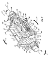
- an agricultural combine 10 including an integrated axle and cleaning fan wrapper 12 constructed and operable according to the present invention.
- Integrated axle and cleaning fan wrapper 12 includes a fan wrapper structure 14 enclosing and containing a cleaning fan 16 operable for blowing a flow of air upwardly and rearwardly, as denoted by arrows A in Figure 1 , through sieves of a cleaning system 18 of combine 10 operable in the well-known manner for separating material other than grain from grain harvested by combine 10.
- Integrated axle and cleaning fan wrapper 12 additionally includes a first axle structure 20, and a second axle structure 22, on opposite sides of combine 10 for connection of drive wheels thereto, as represented by drive wheel 24 in Figure 1 .
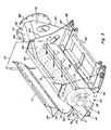
- fan wrapper structure 14 includes a lower wrapper portion 26, preferably of sheet metal construction, which extends sidewardly or laterally between lower regions of a first side sheet 28 and a generally parallel, second side sheet 30 (both side sheets shown in Figure 2 ) of a frame 32 of combine 10.
- Fan wrapper structure 14 includes an upper wrapper portion 34, also preferably of sheet metal construction, which extends sidewardly or laterally between first side sheet 28 and second side sheet 30, in spaced relation to and generally above a portion of lower wrapper portion 26, defining or forming an interior cavity 36 therebetween.
- Wrapper portions 26 and 34 can be suitably attached to side sheets 28 and 30, such as by welding, fasteners, or the like.
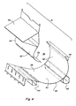
- Lower wrapper portion 26 includes a surface 38 facing interior cavity 36 and which preferably has a concave shape including a lower portion 40 which defines and encloses a lower periphery of interior cavity 36, and a forward portion 42 which defines and encloses a forward periphery of cavity 36.
- Cavity 36 is of sufficient sideward and sectional extent so as to accommodate a conventional cleaning fan therein, such as fan 16 which is a centrifugal or cross flow fan of conventional construction and operation commonly used for combine cleaning systems.
- Lower wrapper portion 26 additionally includes or incorporates structural cross members 44, 46 and 48 therein, which cross members 44, 46 and 48 extend sidewardly along the wrapper portion 26, preferably outside of interior cavity 36, at predetermined locations between first and second side sheets 28 and 30.
- Upper wrapper portion 34 includes a concave surface 50 which faces and defines a rearward periphery of interior cavity 16, and an opposite convex surface 52 both of which function as air flow guides, concave surface 50 for directing air flow from structure portion 14 to the cleaning system 18 ( Figure 1 ), and convex surface 52 for directing air flow into interior cavity 16.
- Upper wrapper portion 34 additionally includes or incorporates a structural cross member 54 which extends sidewardly therealong outside of and above interior cavity 36, between first and second side sheets 28 and 30.
- Cross member 54 also is positioned beneath the inlet region of a threshing system of the combine, so as to serve as a deflector for deflecting grain onto an upper sieve of the cleaning system.
- lower wrapper portion 26 and upper wrapper portion 34 define a forwardly facing air inlet opening 56 ( Figure 3 ), and a rearwardly and upwardly facing air outlet opening 58, both of which can extend the full width or sideward extent of the space between side sheets 28 and 30 as shown.
- lower portion 40 of lower wrapper portion 26 is shown in dotted lines, to illustrate that it is removable, such as for servicing fan 16 or cleaning.
- lower wrapper portion 26, upper wrapper portion 34, and cross members 44, 46, 48 and 54 are positioned and configured to support first and second side sheets 28 and 30, and to serve as structural members disposed between and in support of first and second axle structures 20 and 22, as will be explained next.
- additional cross members 60 and 62 will be provided at different locations in connection with side sheets 28 and 30 for stiffening those members, as well as for supporting other components of combine 10, and for further enclosing interior cavity 36, some of which additional structural members complement and function in concert with the components of integrated axle and cleaning fan wrapper 12 of the invention, for providing a robust and strong combine frame or chassis.
- first and second axle structures 20 and 22 connect with forward drive wheels disposed on opposite sides of combine 10, respectively, as illustrated by drive wheel 24.
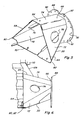
- Axle structures 20 and 22 are essentially mirror images of one another, and each comprises a multiple sided sheet metal three-dimensional structure which extends sidewardly or laterally outwardly from a mounting end portion 64 in connection with the respective side sheet 28 or 30 to an outer end portion 66.
- Each of axle structures 20 and 22 is preferably hollow, and has a shape which tapers convergingly or narrowingly as it extends sidewardly outwardly from mounting end portion 64 toward the outer end portion 66 thereof.
- each axle structure 20 and 22 (as represented by axle structure 20) generally includes a rear sheet 68, a bottom sheet 70, a forward sheet 72 and an upper sheet 74.
- Rear sheet 68 and the rearward portion of bottom sheet 70 are preferably fabricated from a single folded sheet, as are the forward portion of bottom sheet 70 and forward sheet 72, the two sheets being joined at about the centre of bottom sheet 70, using a suitable sheet-metal joint and/or by welding.
- Upper sheet 74 overlays and is connected to the upper regions of sheets 68 and 72, again, utilizing a suitable joint and/or by welding.
- the sides of axle structure 20 taper convergingly from mounting end portion 64 to outer end portion 66.
- Suitable access openings 76 in rear sheet 68 and forward sheet 72 provide access to an interior 78.
- mounting end portion 64 of each axle structure 20 or 22 is welded and/or otherwise suitably attached such as with fasteners, to the adjacent side sheet 28 or 30 at predetermined locations so as to essentially be aligned in the sideward direction and integrate with certain of the structural elements associated with fan wrapper structure 14, in particular, cross members 44, 46, 48, 60 and 62, so as to form a continuous structure extending between the opposite outer end portions 66 of the axle structures.
- cross members 44, 46, 60 and 62 define the corners or boundaries of a multiple sided shape, denoted by dotted line B, which shape matches or corresponds closely with the multiple sided shape and size of mounting end portion 64 of first axle structure 20.
- Second axle structure 22 is a mirror image of first axle structure 20, and thus it can be seen that it will overlay line B when attached to side sheet 30.
- corners 80, 82 and 84 of first and second axle structures 20 and 22 align in the sideward direction and are connected together by cross members 44, 60 and 62, forming a continuous, sidewardly extending three-dimensional axle framework or structure.
- This axle framework or structure preferably envelopes or contains lower wrapper portion 26 which incorporates cross member 44 of this structure or framework, and also cross members 46 and 48, thus integrating the axle structures 20 and 22 with fan wrapper structure 14.
- Lower wrapper portion 26 and upper wrapper portion reinforce and stiffen and strengthen this integrated structure while also enclosing the interior cavity 36.
- arrows C in Figures 1 , 2 and 3 illustrate air flow into fan wrapper structure 14 as generated by rotation of cleaning fan 16, while arrows A illustrate air flow from structure 14 ( Figures 1 and 3 ) to cleaning system 18 ( Figure 1 ).
- the structure of the invention is strong and robust, yet allows air flow directly therethrough.
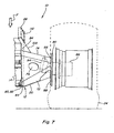
- each axle structure 20 and 22 connects to a drive wheel of combine 10, illustrated by drive wheel 24 in Figures 1 and 7 .
- Each drive wheel is preferably drivingly rotated by a wheel drive unit 86 connecting the drive wheel to the respective axle structure 20 or 22.
- Each axle structure 20 and 22 includes a circular mounting flange 88 attached to outer end portion 66 for this purpose.
- Each wheel drive unit 86 includes a mating flange 90, and flanges 88 and 90 are suitably connected together, for instance, using bolts (not shown) through aligned arrays of bolt holes 92 around the respective flanges.
- Each wheel drive unit 86 is preferably a fluid powered planetary drive unit, including a fluid motor 94 ( Figure 7 ) disposed within a hollow cavity of the respective axle structure 20 and 22, and suitably connected to a source of pressurised fluid and a fluid reservoir (both not shown) of combine 10 in the conventional, well-known manner, via fluid lines 96 and 98 and a valve 100 ( Figure 2 ). Rotation of motor 94 effects rotation of internal components of drive unit 86, to effect rotation of the wheel 24.
- FIG. 8 an alternative drive arrangement for combine 10 is illustrated.
- end reductions or planetary wheel drive units 102 of conventional construction and operation are shown installable on mounting flanges 88 of axle structures 20 and 22 of integrated axle and cleaning fan wrapper 12 of the invention.
- a transmission 104 is illustrated mounted between the forward ends of side sheets 28 and 30.
- Drive shafts (not shown) are then connectable between transmission 104 and respective drive units 102, as illustrated by arrows D, for transmitting power from a power plant (not shown) of combine 10 to the drive wheels.
- integrated axle and cleaning fan wrapper 12 of the invention will be subjected to substantial static loading conditions, including, but not limited to, the weight of a significant portion of combine 10, a header (not shown) mounted thereon, and any grain contained in a grain tank thereof, which loads are collectively denoted by arrows F.
- substantial dynamic loads for instance, but not limited to, torque loads denoted by arrows T will be also generated by driving rotation of the drive wheels, and torque loads denoted by arrows T1 will be generated by movement over uneven terrain, hillsides, and the like.
- Integrated axle and cleaning fan wrapper 12 is designed to maintain wheel drive units 86 in sidewardly aligned relation about a drive axis 106, in opposition to all of the contemplated loading conditions, F, T and T1.
- supplemental braces can be used, as required for reinforcement and integration of the structure of the invention with the structure of the combine, to direct and distribute loads to desired portions of integrated axle and cleaning fan wrapper 12.
- braces 108 are illustrated integrating each axle structure 20 and 22 with a top rail 110 of the associated side sheet 28 and 30.
- the shape and configuration of the various elements of integrated axle and cleaning fan wrapper 12, the gauge of the sheet metal used, and the construction and selection of interlocking seams, welds and the like, for a particular application can be determined, for instance, by analysis, which can include, but is not limited to, finite element analysis.
Landscapes
- Engineering & Computer Science (AREA)
- Mechanical Engineering (AREA)
- Life Sciences & Earth Sciences (AREA)
- Environmental Sciences (AREA)
- Harvester Elements (AREA)
- Combines (AREA)
- Structures Of Non-Positive Displacement Pumps (AREA)
- Harvesting Machines For Root Crops (AREA)
Claims (14)
- Ensemble d'arbre et d'enveloppe de ventilateur de nettoyage (12) pour une machine de récolte agricole (10) comportant un système de nettoyage (18), comprenant :une structure d'enveloppe de ventilateur creuse (14) s'étendant au moins en partie autour de et définissant une cavité intérieure (36) configurée pour recevoir un ventilateur de nettoyage (16) à l'intérieur, la structure d'enveloppe de ventilateur (14) ayant une première portion d'extrémité, une seconde portion d'extrémité opposée, et des portions de tôle fine (26, 34) s'étendant entre les première et seconde portions d'extrémité et enveloppant partiellement la cavité intérieure (36) et définissant une ouverture d'admission d'air (56) reliée à la cavité intérieure (36) et une ouverture d'évacuation d'air (58) en connexion avec celle-ci et configurée pour guider un flux d'air (A) produit par le ventilateur de nettoyage (16) vers le système de nettoyage (18) de la machine de récolte (10),une première structure d'arbre extérieure (20) configurée pour y connecter une roue (24), etune seconde structure d'arbre extérieure (22) configurée pour y connecter une roue (24), les première et seconde structures extérieures d'arbre (20, 22) étant disposées dans une relation prédéterminée d'alignement,caractérisé en ce que l'ensemble d'arbre et d'enveloppe de ventilateur de nettoyage est une enveloppe de ventilateur de nettoyage avec un arbre intégré (12), dans lequel :la première structure d'arbre extérieure (20) est connectée avec et s'étend à l'extérieur de la première portion d'extrémité de la structure d'enveloppe de ventilateur (14);la seconde structure d'arbre extérieure (20) est connectée avec et s'étend à l'extérieur de la seconde portion d'extrémité de la structure d'enveloppe de ventilateur (14), etla structure d'enveloppe de ventilateur (14) comprend au moins une traverse (44, 46, 48, 54) s'étendant entre les première et seconde structures d'arbre extérieures (20, 22) et est configurée pour supporter et maintenir les première et seconde structures d'arbre extérieures (20, 22) dans la relation prédéterminée d'alignement.
- Ensemble intégré d'arbre et d'enveloppe de ventilateur de nettoyage selon la revendication 1, caractérisé en ce que les portions de tôle fine comprennent une portion d'enveloppe inférieure (26) définissant et enfermant une périphérie inférieure de la cavité intérieure (36) et une portion d'enveloppe supérieure (34) disposée de manière espacée au-dessus de la portion d'enveloppe inférieure (26) et définissant et enfermant une portion supérieure de la cavité intérieure (36), au moins l'une des portions d'enveloppe incorporant au moins l'une des traverses (44, 46, 48, 54) à l'intérieur.
- Ensemble intégré d'arbre et d'enveloppe de ventilateur de nettoyage selon la revendication 2, caractérisé en ce qu'au moins l'une des portions supérieure et inférieure d'enveloppe (26, 34) comprend au moins deux des traverses (44, 46, 48, 54) incorporées à l'intérieur.
- Ensemble intégré d'arbre et d'enveloppe de ventilateur de nettoyage selon la revendication 2 ou 3, caractérisé en ce que la portion inférieure de l'enveloppe (26) incorpore à l'intérieur au moins l'une des traverses (44, 46) à l'extérieur de la cavité intérieure (36).
- Ensemble intégré d'arbre et d'enveloppe de ventilateur de nettoyage selon l'une quelconque des revendications précédentes, caractérisé en ce que la structure d'enveloppe de ventilateur (14) et les première et seconde structures d'arbre (20, 22) comprennent respectivement des structures en tôle fine métallique.
- Ensemble intégré d'arbre et d'enveloppe de ventilateur de nettoyage selon la revendication 5, caractérisé en ce que la structure d'enveloppe de ventilateur (14) comprend un élément inférieur en tôle métallique fine (26) ayant une forme concave faisant face vers le haut, et un élément supérieur en tôle métallique fine (34) écarté vers le haut vis-à-vis de l'élément inférieur en tôle métallique fine, les éléments en tôle métallique fine définissant l'ouverture d'admission d'air (56) et l'ouverture d'évacuation d'air (58) entre eux.
- Ensemble intégré d'arbre et d'enveloppe de ventilateur de nettoyage selon l'une quelconque des revendications précédentes, caractérisé en ce que chacune des structures d'arbre extérieures (20, 22) a une forme effilée qui s'étend de manière convergente vers une extrémité extérieure (66) d'entre eux.
- Ensemble intégré d'arbre et d'enveloppe de ventilateur de nettoyage selon l'une quelconque des revendications précédentes, caractérisé en ce que au moins une des structures d'arbre extérieures (20, 22) supporte au-dessus de celle-ci un organe d'entraînement de roue (86/102) configuré pour entraîner en rotation une roue (24) connectée à celui-ci.
- Ensemble intégré d'arbre et d'enveloppe de ventilateur de nettoyage selon la revendication 8, caractérisé en ce que chaque structure d'arbre extérieure (20, 22) comprend une structure creuse incluant une plaque de montage longitudinalement terminale (88) configurée pour monter sur celle-ci un organe d'entraînement de roue (86/102).
- Ensemble intégré d'arbre et d'enveloppe de ventilateur de nettoyage selon la revendication 8 ou 9, caractérisé en ce l'organe d'entraînement de roue comprend une réduction finale (102).
- Ensemble intégré d'arbre et d'enveloppe de ventilateur de nettoyage selon la revendication 8 ou 9, caractérisé en ce l'organe d'entraînement de roue comprend un moteur hydraulique (94).
- Ensemble intégré d'arbre et d'enveloppe de ventilateur de nettoyage selon l'une quelconque des revendications précédentes, caractérisé en ce que:il comprend des première et seconde tôles fines latérales (28, 30) reliées respectivement aux première et seconde portions d'extrémité de la structure d'enveloppe de ventilateur (14), etla première structure d'arbre (20) est montée de manière attenante à la première tôle latérale (28), latéralement à l'extérieur de la structure d'enveloppe de ventilateur (14);la seconde structure d'arbre (22) est montée de manière attenante à la seconde tôle latérale (30), latéralement à l'extérieur de la structure d'enveloppe de ventilateur (14); etla au moins une traverse (44, 46, 48, 54) est reliée aux et entre les tôles latérales (28, 30) pour maintenir les tôles latérales dans une relation écartée généralement parallèle et les structures d'arbre (20, 22) dans la relation alignée prédéterminée.
- Machine de récolte agricole (10) comprenant un châssis (32) comportant des tôles latérales (28, 30), caractérisée en ce qu'elle comprend un ensemble d'arbre et d'enveloppe de ventilateur de nettoyage intégré (12) selon l'une quelconque des revendications précédentes, dans laquelle au moins l'une des parties d'embout de la structure d'enveloppe (14) est enceinte par l'une des tôles latérales (28, 30) du châssis (32).
- Machine de récolte agricole selon la revendication 13, caractérisée en ce que les enveloppes de ventilateur de nettoyage et d'arbre intégrées (12) sont incorporées dans le châssis (32).
Applications Claiming Priority (1)
| Application Number | Priority Date | Filing Date | Title |
|---|---|---|---|
| US11/638,026 US7670219B2 (en) | 2006-12-13 | 2006-12-13 | Integrated axle and cleaning fan wrapper for an agricultural harvesting machine |
Publications (2)
| Publication Number | Publication Date |
|---|---|
| EP1932421A1 EP1932421A1 (fr) | 2008-06-18 |
| EP1932421B1 true EP1932421B1 (fr) | 2010-02-17 |
Family
ID=39135259
Family Applications (1)
| Application Number | Title | Priority Date | Filing Date |
|---|---|---|---|
| EP07123083A Active EP1932421B1 (fr) | 2006-12-13 | 2007-12-12 | Axe et enveloppe de ventilateur de nettoyage intégrées pour moissonneuse agricole |
Country Status (4)
| Country | Link |
|---|---|
| US (1) | US7670219B2 (fr) |
| EP (1) | EP1932421B1 (fr) |
| AT (1) | ATE457631T1 (fr) |
| DE (1) | DE602007004800D1 (fr) |
Cited By (1)
| Publication number | Priority date | Publication date | Assignee | Title |
|---|---|---|---|---|
| US9469342B2 (en) | 2014-08-29 | 2016-10-18 | Deere & Company | Axle and transmission arrangement for an agricultural vehicle |
Families Citing this family (10)
| Publication number | Priority date | Publication date | Assignee | Title |
|---|---|---|---|---|
| US8286984B2 (en) * | 2007-12-18 | 2012-10-16 | Dillon Ben N | Articulated combine with unloading and rear bogey steering architecture |
| US8221064B2 (en) | 2008-11-18 | 2012-07-17 | Cnh America Llc | Transverse fan assembly having a supplementary air feed inlet for infill of air flow deficiencies to effect a desired output air flow pattern, and method of use thereof |
| DE102011050207A1 (de) | 2011-05-09 | 2012-11-15 | Amazonen-Werke H. Dreyer Gmbh & Co. Kg | Landwirtschaftliche Feldspritze |
| GB201221347D0 (en) * | 2012-11-28 | 2013-01-09 | Agco As | Crop processing apparatus in a combine harvester |
| US9033779B2 (en) * | 2012-11-29 | 2015-05-19 | Cnh Industrial America Llc | Air diverter for a cleaning system of a combine harvester |
| US9750192B2 (en) * | 2014-08-29 | 2017-09-05 | Deere & Company | Integrated fan and axle arrangement for an agricultural vehicle |
| US10561069B2 (en) * | 2017-10-06 | 2020-02-18 | Cnh Industrial America Llc | Segmented fan housing for cleaning system of combine harvester |
| JP6887519B2 (ja) * | 2017-10-25 | 2021-06-16 | 株式会社クボタ | コンバイン |
| US10791676B2 (en) | 2018-03-28 | 2020-10-06 | Cnh Industrial America Llc | Modular combine traction axle |
| US10986777B2 (en) * | 2018-04-25 | 2021-04-27 | Cnh Industrial America Llc | Vented side member for an agricultural vehicle |
Family Cites Families (21)
| Publication number | Priority date | Publication date | Assignee | Title |
|---|---|---|---|---|
| US876681A (en) | 1907-04-03 | 1908-01-14 | Charles Batke | Combined thresher and separator. |
| US1625365A (en) | 1921-08-27 | 1927-04-19 | Louis Kraus | Standing-grain thrasher |
| US2496022A (en) | 1946-06-03 | 1950-01-31 | Remonte John | Electric lawn mower |
| US2612742A (en) * | 1947-12-05 | 1952-10-07 | Case Co J I | Grain combine |
| US2849118A (en) * | 1956-02-20 | 1958-08-26 | Massey Ferguson Inc | Fanning mill for combines |
| US3469773A (en) * | 1968-07-12 | 1969-09-30 | Int Harvester Co | Fan for combine |
| US3664349A (en) * | 1969-12-19 | 1972-05-23 | Univ Iowa State Res Found | Combine cleaning blower |
| CA948950A (en) * | 1971-11-22 | 1974-06-11 | Western Roto Thresh Ltd. | Pneumatic rotary classifier |
| DE2922607A1 (de) * | 1979-06-02 | 1981-01-08 | Claas Ohg | Geblaese fuer die reinigungsvorrichtung von maehdreschern |
| US4265077A (en) * | 1979-08-03 | 1981-05-05 | Deere & Company | Blower system for an axial flow rotary combine cleaning shoe |
| US4353376A (en) * | 1981-03-12 | 1982-10-12 | Schuler Murry W | Combine having separating and cleaning apparatus |
| EP0250654B1 (fr) | 1986-07-01 | 1990-09-05 | Ford New Holland N.V. | Moissonneuse-batteuse |
| EP0291582B1 (fr) * | 1987-05-19 | 1991-12-11 | Ford New Holland N.V. | Appareil de nettoyage pour moissonneuse-batteuse |
| US4906219A (en) * | 1988-08-15 | 1990-03-06 | J. I. Case Company | Cleaning system for a combine |
| US5387154A (en) * | 1993-05-10 | 1995-02-07 | Deere & Company | Two outlet cleaning fan |
| GB9407578D0 (en) | 1994-04-13 | 1994-06-08 | Reekie Mfg Ltd | Chassis system |
| US5599162A (en) * | 1995-08-09 | 1997-02-04 | Case Corporation | Transverse blower fan assembly |
| US5895319A (en) | 1996-12-19 | 1999-04-20 | Case Corporation | Air intake system for an off-highway machine |
| US6442916B1 (en) | 2000-11-17 | 2002-09-03 | Case Corporation | Sensing system for an agricultural combine |
| US6773343B2 (en) * | 2002-07-31 | 2004-08-10 | Deere & Company | Front chaffer and cleaning fan |
| US6953121B2 (en) | 2003-05-06 | 2005-10-11 | Johnson Crushers International | Vibrating screen |
-
2006
- 2006-12-13 US US11/638,026 patent/US7670219B2/en not_active Expired - Fee Related
-
2007
- 2007-12-12 DE DE602007004800T patent/DE602007004800D1/de active Active
- 2007-12-12 AT AT07123083T patent/ATE457631T1/de not_active IP Right Cessation
- 2007-12-12 EP EP07123083A patent/EP1932421B1/fr active Active
Cited By (1)
| Publication number | Priority date | Publication date | Assignee | Title |
|---|---|---|---|---|
| US9469342B2 (en) | 2014-08-29 | 2016-10-18 | Deere & Company | Axle and transmission arrangement for an agricultural vehicle |
Also Published As
| Publication number | Publication date |
|---|---|
| DE602007004800D1 (de) | 2010-04-01 |
| EP1932421A1 (fr) | 2008-06-18 |
| US20080146299A1 (en) | 2008-06-19 |
| US7670219B2 (en) | 2010-03-02 |
| ATE457631T1 (de) | 2010-03-15 |
Similar Documents
| Publication | Publication Date | Title |
|---|---|---|
| EP1932421B1 (fr) | Axe et enveloppe de ventilateur de nettoyage intégrées pour moissonneuse agricole | |
| US4060960A (en) | Self-propelled crop harvester | |
| CN101472464B (zh) | 联合收割机 | |
| EP2992752B1 (fr) | Agencement d'essieu et ventilateur intégré pour un véhicule agricole | |
| US9469342B2 (en) | Axle and transmission arrangement for an agricultural vehicle | |
| JP4755030B2 (ja) | コンバイン | |
| JP7458447B2 (ja) | コンバイン | |
| JP6440595B2 (ja) | コンバイン及び農業作業車 | |
| CN203378294U (zh) | 脱粒装置 | |
| EP3545751B1 (fr) | Essieu de traction modulaire pour moissonneuse-batteuse | |
| JP2008000032A (ja) | コンバイン | |
| CN112567965B (zh) | 联合收割机、用于运输联合收割机的方法和布置 | |
| JP2022101185A (ja) | サトウキビ収穫機 | |
| US6474054B2 (en) | Rear discharge mower | |
| JP6440594B2 (ja) | クローラ走行装置 | |
| JP7068833B2 (ja) | 収穫機 | |
| JP7321037B2 (ja) | サトウキビ収穫機 | |
| JP4040208B2 (ja) | コンバイン | |
| JP2008000033A (ja) | コンバイン | |
| JP2008000028A (ja) | コンバイン | |
| JP7262349B2 (ja) | サトウキビ収穫機 | |
| JP2008000030A (ja) | コンバイン | |
| JP2025131239A (ja) | サトウキビ収穫機 | |
| JP2008000035A (ja) | コンバイン | |
| JP2000316356A (ja) | コンバイン |
Legal Events
| Date | Code | Title | Description |
|---|---|---|---|
| PUAI | Public reference made under article 153(3) epc to a published international application that has entered the european phase |
Free format text: ORIGINAL CODE: 0009012 |
|
| AK | Designated contracting states |
Kind code of ref document: A1 Designated state(s): AT BE BG CH CY CZ DE DK EE ES FI FR GB GR HU IE IS IT LI LT LU LV MC MT NL PL PT RO SE SI SK TR |
|
| AX | Request for extension of the european patent |
Extension state: AL BA HR MK RS |
|
| 17P | Request for examination filed |
Effective date: 20081218 |
|
| AKX | Designation fees paid |
Designated state(s): AT BE BG CH CY CZ DE DK EE ES FI FR GB GR HU IE IS IT LI LT LU LV MC MT NL PL PT RO SE SI SK TR |
|
| GRAP | Despatch of communication of intention to grant a patent |
Free format text: ORIGINAL CODE: EPIDOSNIGR1 |
|
| GRAS | Grant fee paid |
Free format text: ORIGINAL CODE: EPIDOSNIGR3 |
|
| GRAA | (expected) grant |
Free format text: ORIGINAL CODE: 0009210 |
|
| AK | Designated contracting states |
Kind code of ref document: B1 Designated state(s): AT BE BG CH CY CZ DE DK EE ES FI FR GB GR HU IE IS IT LI LT LU LV MC MT NL PL PT RO SE SI SK TR |
|
| REG | Reference to a national code |
Ref country code: GB Ref legal event code: FG4D |
|
| REG | Reference to a national code |
Ref country code: CH Ref legal event code: EP |
|
| REG | Reference to a national code |
Ref country code: IE Ref legal event code: FG4D |
|
| REF | Corresponds to: |
Ref document number: 602007004800 Country of ref document: DE Date of ref document: 20100401 Kind code of ref document: P |
|
| REG | Reference to a national code |
Ref country code: NL Ref legal event code: VDEP Effective date: 20100217 |
|
| LTIE | Lt: invalidation of european patent or patent extension |
Effective date: 20100217 |
|
| PG25 | Lapsed in a contracting state [announced via postgrant information from national office to epo] |
Ref country code: PT Free format text: LAPSE BECAUSE OF FAILURE TO SUBMIT A TRANSLATION OF THE DESCRIPTION OR TO PAY THE FEE WITHIN THE PRESCRIBED TIME-LIMIT Effective date: 20100617 Ref country code: LT Free format text: LAPSE BECAUSE OF FAILURE TO SUBMIT A TRANSLATION OF THE DESCRIPTION OR TO PAY THE FEE WITHIN THE PRESCRIBED TIME-LIMIT Effective date: 20100217 Ref country code: IS Free format text: LAPSE BECAUSE OF FAILURE TO SUBMIT A TRANSLATION OF THE DESCRIPTION OR TO PAY THE FEE WITHIN THE PRESCRIBED TIME-LIMIT Effective date: 20100617 Ref country code: ES Free format text: LAPSE BECAUSE OF FAILURE TO SUBMIT A TRANSLATION OF THE DESCRIPTION OR TO PAY THE FEE WITHIN THE PRESCRIBED TIME-LIMIT Effective date: 20100528 |
|
| PG25 | Lapsed in a contracting state [announced via postgrant information from national office to epo] |
Ref country code: SI Free format text: LAPSE BECAUSE OF FAILURE TO SUBMIT A TRANSLATION OF THE DESCRIPTION OR TO PAY THE FEE WITHIN THE PRESCRIBED TIME-LIMIT Effective date: 20100217 Ref country code: PL Free format text: LAPSE BECAUSE OF FAILURE TO SUBMIT A TRANSLATION OF THE DESCRIPTION OR TO PAY THE FEE WITHIN THE PRESCRIBED TIME-LIMIT Effective date: 20100217 Ref country code: LV Free format text: LAPSE BECAUSE OF FAILURE TO SUBMIT A TRANSLATION OF THE DESCRIPTION OR TO PAY THE FEE WITHIN THE PRESCRIBED TIME-LIMIT Effective date: 20100217 Ref country code: FI Free format text: LAPSE BECAUSE OF FAILURE TO SUBMIT A TRANSLATION OF THE DESCRIPTION OR TO PAY THE FEE WITHIN THE PRESCRIBED TIME-LIMIT Effective date: 20100217 Ref country code: AT Free format text: LAPSE BECAUSE OF FAILURE TO SUBMIT A TRANSLATION OF THE DESCRIPTION OR TO PAY THE FEE WITHIN THE PRESCRIBED TIME-LIMIT Effective date: 20100217 |
|
| PG25 | Lapsed in a contracting state [announced via postgrant information from national office to epo] |
Ref country code: SE Free format text: LAPSE BECAUSE OF FAILURE TO SUBMIT A TRANSLATION OF THE DESCRIPTION OR TO PAY THE FEE WITHIN THE PRESCRIBED TIME-LIMIT Effective date: 20100217 Ref country code: RO Free format text: LAPSE BECAUSE OF FAILURE TO SUBMIT A TRANSLATION OF THE DESCRIPTION OR TO PAY THE FEE WITHIN THE PRESCRIBED TIME-LIMIT Effective date: 20100217 Ref country code: NL Free format text: LAPSE BECAUSE OF FAILURE TO SUBMIT A TRANSLATION OF THE DESCRIPTION OR TO PAY THE FEE WITHIN THE PRESCRIBED TIME-LIMIT Effective date: 20100217 Ref country code: GR Free format text: LAPSE BECAUSE OF FAILURE TO SUBMIT A TRANSLATION OF THE DESCRIPTION OR TO PAY THE FEE WITHIN THE PRESCRIBED TIME-LIMIT Effective date: 20100518 Ref country code: EE Free format text: LAPSE BECAUSE OF FAILURE TO SUBMIT A TRANSLATION OF THE DESCRIPTION OR TO PAY THE FEE WITHIN THE PRESCRIBED TIME-LIMIT Effective date: 20100217 Ref country code: CY Free format text: LAPSE BECAUSE OF FAILURE TO SUBMIT A TRANSLATION OF THE DESCRIPTION OR TO PAY THE FEE WITHIN THE PRESCRIBED TIME-LIMIT Effective date: 20100217 |
|
| PG25 | Lapsed in a contracting state [announced via postgrant information from national office to epo] |
Ref country code: SK Free format text: LAPSE BECAUSE OF FAILURE TO SUBMIT A TRANSLATION OF THE DESCRIPTION OR TO PAY THE FEE WITHIN THE PRESCRIBED TIME-LIMIT Effective date: 20100217 Ref country code: CZ Free format text: LAPSE BECAUSE OF FAILURE TO SUBMIT A TRANSLATION OF THE DESCRIPTION OR TO PAY THE FEE WITHIN THE PRESCRIBED TIME-LIMIT Effective date: 20100217 Ref country code: BG Free format text: LAPSE BECAUSE OF FAILURE TO SUBMIT A TRANSLATION OF THE DESCRIPTION OR TO PAY THE FEE WITHIN THE PRESCRIBED TIME-LIMIT Effective date: 20100517 |
|
| PLBE | No opposition filed within time limit |
Free format text: ORIGINAL CODE: 0009261 |
|
| STAA | Information on the status of an ep patent application or granted ep patent |
Free format text: STATUS: NO OPPOSITION FILED WITHIN TIME LIMIT |
|
| 26N | No opposition filed |
Effective date: 20101118 |
|
| PG25 | Lapsed in a contracting state [announced via postgrant information from national office to epo] |
Ref country code: DK Free format text: LAPSE BECAUSE OF FAILURE TO SUBMIT A TRANSLATION OF THE DESCRIPTION OR TO PAY THE FEE WITHIN THE PRESCRIBED TIME-LIMIT Effective date: 20100217 |
|
| PG25 | Lapsed in a contracting state [announced via postgrant information from national office to epo] |
Ref country code: MC Free format text: LAPSE BECAUSE OF NON-PAYMENT OF DUE FEES Effective date: 20101231 |
|
| PG25 | Lapsed in a contracting state [announced via postgrant information from national office to epo] |
Ref country code: IE Free format text: LAPSE BECAUSE OF NON-PAYMENT OF DUE FEES Effective date: 20101212 |
|
| PG25 | Lapsed in a contracting state [announced via postgrant information from national office to epo] |
Ref country code: IT Free format text: LAPSE BECAUSE OF NON-PAYMENT OF DUE FEES Effective date: 20101212 Ref country code: MT Free format text: LAPSE BECAUSE OF FAILURE TO SUBMIT A TRANSLATION OF THE DESCRIPTION OR TO PAY THE FEE WITHIN THE PRESCRIBED TIME-LIMIT Effective date: 20100217 |
|
| REG | Reference to a national code |
Ref country code: CH Ref legal event code: PL |
|
| PG25 | Lapsed in a contracting state [announced via postgrant information from national office to epo] |
Ref country code: LU Free format text: LAPSE BECAUSE OF NON-PAYMENT OF DUE FEES Effective date: 20101212 Ref country code: HU Free format text: LAPSE BECAUSE OF FAILURE TO SUBMIT A TRANSLATION OF THE DESCRIPTION OR TO PAY THE FEE WITHIN THE PRESCRIBED TIME-LIMIT Effective date: 20100818 |
|
| PG25 | Lapsed in a contracting state [announced via postgrant information from national office to epo] |
Ref country code: CH Free format text: LAPSE BECAUSE OF NON-PAYMENT OF DUE FEES Effective date: 20111231 Ref country code: TR Free format text: LAPSE BECAUSE OF FAILURE TO SUBMIT A TRANSLATION OF THE DESCRIPTION OR TO PAY THE FEE WITHIN THE PRESCRIBED TIME-LIMIT Effective date: 20100217 Ref country code: LI Free format text: LAPSE BECAUSE OF NON-PAYMENT OF DUE FEES Effective date: 20111231 |
|
| REG | Reference to a national code |
Ref country code: DE Ref legal event code: R082 Ref document number: 602007004800 Country of ref document: DE Representative=s name: PATENTANWAELTE WALLACH, KOCH & PARTNER, DE |
|
| REG | Reference to a national code |
Ref country code: DE Ref legal event code: R082 Ref document number: 602007004800 Country of ref document: DE Representative=s name: PATENTANWAELTE WALLACH, KOCH, DR. HAIBACH, FEL, DE Effective date: 20140428 Ref country code: DE Ref legal event code: R082 Ref document number: 602007004800 Country of ref document: DE Representative=s name: PATENTANWAELTE WALLACH, KOCH & PARTNER, DE Effective date: 20140428 Ref country code: DE Ref legal event code: R081 Ref document number: 602007004800 Country of ref document: DE Owner name: CNH INDUSTRIAL BELGIUM NV, BE Free format text: FORMER OWNER: CNH BELGIUM NV, ZEDELGEM, BE Effective date: 20140428 |
|
| REG | Reference to a national code |
Ref country code: FR Ref legal event code: CD Owner name: CNH INDUSTRIAL BELGIUM NV Effective date: 20140725 |
|
| REG | Reference to a national code |
Ref country code: FR Ref legal event code: PLFP Year of fee payment: 9 |
|
| REG | Reference to a national code |
Ref country code: FR Ref legal event code: PLFP Year of fee payment: 10 |
|
| REG | Reference to a national code |
Ref country code: FR Ref legal event code: PLFP Year of fee payment: 11 |
|
| REG | Reference to a national code |
Ref country code: FR Ref legal event code: PLFP Year of fee payment: 12 |
|
| PGFP | Annual fee paid to national office [announced via postgrant information from national office to epo] |
Ref country code: BE Payment date: 20191220 Year of fee payment: 13 |
|
| PGFP | Annual fee paid to national office [announced via postgrant information from national office to epo] |
Ref country code: GB Payment date: 20191220 Year of fee payment: 13 |
|
| REG | Reference to a national code |
Ref country code: DE Ref legal event code: R084 Ref document number: 602007004800 Country of ref document: DE |
|
| GBPC | Gb: european patent ceased through non-payment of renewal fee |
Effective date: 20201212 |
|
| REG | Reference to a national code |
Ref country code: BE Ref legal event code: MM Effective date: 20201231 |
|
| PG25 | Lapsed in a contracting state [announced via postgrant information from national office to epo] |
Ref country code: GB Free format text: LAPSE BECAUSE OF NON-PAYMENT OF DUE FEES Effective date: 20201212 |
|
| PG25 | Lapsed in a contracting state [announced via postgrant information from national office to epo] |
Ref country code: BE Free format text: LAPSE BECAUSE OF NON-PAYMENT OF DUE FEES Effective date: 20201231 |
|
| PGFP | Annual fee paid to national office [announced via postgrant information from national office to epo] |
Ref country code: IT Payment date: 20221206 Year of fee payment: 16 Ref country code: FR Payment date: 20221216 Year of fee payment: 16 |
|
| PG25 | Lapsed in a contracting state [announced via postgrant information from national office to epo] |
Ref country code: FR Free format text: LAPSE BECAUSE OF NON-PAYMENT OF DUE FEES Effective date: 20231231 |
|
| PG25 | Lapsed in a contracting state [announced via postgrant information from national office to epo] |
Ref country code: FR Free format text: LAPSE BECAUSE OF NON-PAYMENT OF DUE FEES Effective date: 20231231 |
|
| PG25 | Lapsed in a contracting state [announced via postgrant information from national office to epo] |
Ref country code: IT Free format text: LAPSE BECAUSE OF NON-PAYMENT OF DUE FEES Effective date: 20231212 |
|
| PGFP | Annual fee paid to national office [announced via postgrant information from national office to epo] |
Ref country code: DE Payment date: 20251229 Year of fee payment: 19 |