EP1932468A2 - Sphygmomanomètre - Google Patents
Sphygmomanomètre Download PDFInfo
- Publication number
- EP1932468A2 EP1932468A2 EP07024132A EP07024132A EP1932468A2 EP 1932468 A2 EP1932468 A2 EP 1932468A2 EP 07024132 A EP07024132 A EP 07024132A EP 07024132 A EP07024132 A EP 07024132A EP 1932468 A2 EP1932468 A2 EP 1932468A2
- Authority
- EP
- European Patent Office
- Prior art keywords
- block
- cuff
- sphygmomanometer
- angle
- base
- Prior art date
- Legal status (The legal status is an assumption and is not a legal conclusion. Google has not performed a legal analysis and makes no representation as to the accuracy of the status listed.)
- Granted
Links
- 239000008280 blood Substances 0.000 claims abstract description 5
- 210000004369 blood Anatomy 0.000 claims abstract description 5
- 230000036772 blood pressure Effects 0.000 claims description 9
- 238000009530 blood pressure measurement Methods 0.000 description 10
- 238000003780 insertion Methods 0.000 description 9
- 230000037431 insertion Effects 0.000 description 9
- 238000005259 measurement Methods 0.000 description 4
- 230000004048 modification Effects 0.000 description 3
- 238000012986 modification Methods 0.000 description 3
- 210000000245 forearm Anatomy 0.000 description 2
- 230000000149 penetrating effect Effects 0.000 description 1
Images



Classifications
-
- A—HUMAN NECESSITIES
- A61—MEDICAL OR VETERINARY SCIENCE; HYGIENE
- A61B—DIAGNOSIS; SURGERY; IDENTIFICATION
- A61B5/00—Measuring for diagnostic purposes; Identification of persons
- A61B5/02—Detecting, measuring or recording for evaluating the cardiovascular system, e.g. pulse, heart rate, blood pressure or blood flow
- A61B5/021—Measuring pressure in heart or blood vessels
- A61B5/022—Measuring pressure in heart or blood vessels by applying pressure to close blood vessels, e.g. against the skin; Ophthalmodynamometers
- A61B5/02233—Occluders specially adapted therefor
-
- A—HUMAN NECESSITIES
- A61—MEDICAL OR VETERINARY SCIENCE; HYGIENE
- A61B—DIAGNOSIS; SURGERY; IDENTIFICATION
- A61B5/00—Measuring for diagnostic purposes; Identification of persons
- A61B5/02—Detecting, measuring or recording for evaluating the cardiovascular system, e.g. pulse, heart rate, blood pressure or blood flow
- A61B5/021—Measuring pressure in heart or blood vessels
- A61B5/022—Measuring pressure in heart or blood vessels by applying pressure to close blood vessels, e.g. against the skin; Ophthalmodynamometers
Definitions
- the present invention relates to a sphygmomanometer to measure a blood pressure in an upper arm of a user.
- the sphygmomanometer in a type of a sphygmomanometer capable of automatically wrapping an upper arm of a user by a cuff for restricting flow of blood, the sphygmomanometer includes a cuff block having an insertion hole through which a user can insert his/her upper arm.
- the cuff block has the cuff for restricting flow of blood and a wearing cuff mechanism for allowing the cuff to wrap around the upper arm by tightening the cuff.
- a user may not measure his/her blood pressure in an appropriate posture depending on a height of a table on which the sphygmomanometer is put and a physical size of the user.
- a sphygmomanometer in which the cuff block is pivotably connected to a base block placed on, e.g., a table, so that an inclined angle of the cuff block with respect to a horizontal plane can be changed.
- a sphygmomanometer disclosed in Japanese Patent Laid-open Application No.2004-254882 requires a user to adjust the cuff block and keep the angle of the cuff block by using the other arm.
- the present invention provides a sphygmomanometer capable of allowing a user to easily measure a blood pressure at a proper posture.
- a sphygmomanometer including a base block; a cuff block having a cuff for restricting flow of blood, the cuff block being connected to the base block in such a manner that an angle of the cuff block with respect to a horizontal plane is variable within an angular range; and a spring biasing unit for returning the cuff block to a position at a predetermined angle within the variable angular range of the cuff block when the cuff block is not used.
- the cuff block is kept always in a state that a user can easily insert his/her arm into the cuff block. Further, while the user inserts the arm into the cuff block, the inclined angle of the cuff block is changed depending on the angle of the arm. Therefore, the blood pressure can be easily measured in a comfortable posture.
- the predetermined angle is an angle frequently used in the blood pressure measurement.
- the predetermined angle is freely adjustable, a more reliable measurement can be obtained.
- the sphygmomanometer may further includes a lock unit to restrict the change in the angle of the cuff block with respect to the base block so that it is convenient to keep and carry the sphygmomanometer.
- the sphygmomanometer may further includes an elbow supporting block provided with an elbow support for supporting an elbow of a user who inserts his/her arm into the cuff block on the top surface thereof.
- the elbow supporting block is slidably supported on the base block and is connected to the cuff block, so that the elbow supporting unit slides on the base block in accordance with the angular change of the cuff block with respect to the base block. Accordingly a distance from one end of the cuff block to the elbow support is maintained constant even when the angle of the cuff block is changed with respect to the base block. Therefore, a precise blood pressure measurement can be carried out.
- the cuff block may be connected to the base block in such a manner that its horizontal position and its orientation about a vertical axis thereof are variable with respect to the base block or its vertical position is variable with respect to the base block. Therefore, a degree of freedom of the user's arm increases, so that the blood pressure measurement can be carried out at a more comfortable posture.
- the sphygmomanometer may further include a detecting unit for detecting a position of the arm to the cuff block. Accordingly, the blood pressure can be measured in a state of positioning the cuff block at a proper portion of the upper arm.
- the cuff block is always maintained in a state that a user can easily insert into the cuff block so that it is not necessary to apply a preliminarily manipulate the cuff block. Further, since the inclined angle of the cuff block is changed in accordance with an angle of the arm while the arm is inserted into the cuff block, the blood pressure can be easily measured in a comfortable posture.
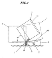
- a cuff block 1 includes a cuff and a wearing cuff mechanism for allowing the cuff to wrap around an upper arm of a user.
- the cuff block has a cylindrical shape, wherein an insertion hole 10 penetrating through the cuff block is provided for inserting an upper arm.
- the cuff block 1 is pivotably connected through a shaft 3 to a base block 2 placed on, e.g., a table, so that an inclined angle thereof with respect to a horizontal plane is changeable.
- a torsion spring 8 is disposed such that one end thereof is fixed to the cuff block 1 and the other end is fixed to the base block 2.
- the torsion spring 8 changes the direction of its biasing force depending on the inclined angle of the cuff block 1, and maintains the cuff block 1 at a predetermined angle ⁇ with respect to the horizontal plane against the cuff block 1 falling down by its weight. Even when the cuff block 1 is pivotally moved such that the angle thereof becomes less or greater than the angle a, if releasing a force applied to the cuff block 1, the cuff block 1 is automatically returned to the position at the angle a by the biasing force of the spring 8.
- the predetermined angle ⁇ is preferably in a range from about 30° to 45°, but is not limited thereto.
- the inclined angle of the cuff block 1 is preferably changed within a range for completely covering the range of the angle a, for example, a range between 0° to 90° .
- the cuff block 1 is normally kept inclined at the angle a, it is not necessary to change the angle in advance when a user inserts his/her arm into the cuff block 1. It is sufficient for the user to insert the arm into the insertion hole 10 of the cuff block 1. Further, while the arm is inserted through the insertion hole 10, the inclined angle of the cuff block 1 is varied depending on an angle of the arm, so that the angle of the cuff block 1 is finally identical to an angle between the upper arm inserted through the insertion hole 10 and the horizontal plane.
- the inclined angle of the cuff block 1 is varied depending on the angle of the arm while the user pulls the arm out of the cuff block 1, so that the user can smoothly pull out the arm without being hindered by the cuff block 1. Furthermore, after pulling out the arm, the cuff block 1 return to the position inclined at the angle a.
- a user may pivotally move the cuff block 1 toward him/her to be oriented approximately horizontal and then insert his/her arm into the cuff block 1.
- the cuff block 1 is pivotally moved up in accordance with an angle of the arm while the arm portion upper than the elbow is inserted through the insertion hole 10. Therefore, it is still not necessary to manually adjust the inclined angle of the cuff block 1 during the insertion of the upper arm.
- the predetermined angle ⁇ may not be proper depending on a height of a table on which the base block 1 is placed or a physical size of a user, it is preferred to provide an adjusting dial 27 to change a spring force of the torsion spring 8 with respect to the cuff block 1 by shifting a fixing unit 26 in the base block 2 in the right-left direction in Fig. 8, the fixing unit 26 being connected to one end of the torsion spring 8.
- the predetermined angle a can be adjusted by shifting the fixing unit 26 with the adjusting dial 27.
- a lock unit 85 for locking the cuff block 1 to the base block 1 as shown in Fig. 2 .
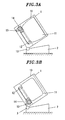
- Figs. 3A and 3B show the wearing cuff mechanism in the cuff block 1.
- reference numerals 11, 12, 13 and 14 respectively indicate the cuff, a wrap drum, a geared motor and a series of reduction gears.
- the wrap drum 12 is rotated by the geared motor 13 through the reduction gears 14, so that the cuff 11 is tightened or released.
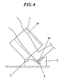
- an elbow support 44 is provided on the top surface of the base block 2 to support an elbow of an arm inserted through the cuff block 1.
- a position of the cuff block 1 on the upper arm is determined by positioning the elbow on the elbow support 44.
- the elbow support 44 may include a switch S to detect whether the elbow is positioned or not. In this case, alarm sound or an alarm sign may be generated when the switch S is not turned on at the start of the blood pressure measurement, or the blood pressure measurement may be started by turning on the switch S. Therefore, it is possible to prevent the blood pressure measurement from being performed in a state where the upper arm is not sufficiently inserted into the cuff block 1.
- Fig. 5 shows an example for a case where the cuff block 1 is pivotably connected to the base block 2 and a member for positioning the elbow is provided on the base block 2.
- An elbow supporting block 4 includes an elbow support 44 for positioning an elbow of a user, and a forearm support 45 for supporting a forearm of a user.
- the elbow supporting block 4 is connected to the cuff block through a hinge shaft 40 at a position slightly offset from the shaft 3. Accordingly, when the cuff block 1 is pivotally moved with respect to the base block 2, the elbow supporting block 4 moves back and forward on the base block 2 in accordance with to the pivotal movement of the cuff block 1.
- the elbow supporting block 4 further includes a guide shaft 41 to slide along a guide groove 21 formed in the base block 2.
- the guide groove 21 provided in the base block 2 has an arc shape and one end thereof away from the shaft 3 is positioned at a lower position than the other end close to the shaft 3.
- the guide groove 21 may have an inclined linear shape). This is for allowing the elbow supporting block 4 to move forward and backward in accordance with the pivotal movements of the cuff block 1 while the inclined angle ⁇ of the elbow supporting block 4 is kept unchanged.
- the guide groove 21 may be a horizontal groove.
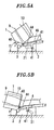
- Figs. 6A and 6B , and 7A and 7B show a sphygmomanometer in accordance with another embodiment of the present invention.
- the cuff block 1 can change its horizontal position and its orientation about a vertical axis thereof with respect to the base block 2, and the base block 2 including a cross-shaped groove 70 formed in the top surface thereof.
- a movable base 71 having a bearing for the shaft 3 is provided and a shaft unit 72 of the movable base 71 is positioned in the groove 70.
- the shaft unit 72 has a substantially same outer diameter as a width of the groove 70.
- the shaft unit 72 moves along the cross-shaped groove 70 so that the position of the cuff block 1 can be shifted forward, backward, left, and right horizontally.
- the orientation of the cuff block about the vertical axis can be changed, as shown in Fig. 7 .
- the position and orientation of the cuff block 1 can be changed depending on the position and orientation of the user's arm. Therefore, the blood pressure measurement can be carried out in a state that the arm is maintained comfortable.
- the cuff block 1 can be also shifted in the vertical position. Therefore, the blood pressure measurement can be carried out in a state that a user keeps the arm comfortable.
- the measurement result is not reliable if the cuff block moves. Therefore, it is preferably to provide at least a lock unit (not shown) for preventing the movement of the movable base 71. Moreover, the change in horizontal position and orientation of the cuff block 1 is effective in view of allowing a user to keep his/her posture comfortable during the measurement even in a case where the cuff block 1 is not pivotable about the shaft 3.
Landscapes
- Health & Medical Sciences (AREA)
- Life Sciences & Earth Sciences (AREA)
- Cardiology (AREA)
- Vascular Medicine (AREA)
- Engineering & Computer Science (AREA)
- Medical Informatics (AREA)
- Physics & Mathematics (AREA)
- Ophthalmology & Optometry (AREA)
- Biophysics (AREA)
- Pathology (AREA)
- Veterinary Medicine (AREA)
- Biomedical Technology (AREA)
- Heart & Thoracic Surgery (AREA)
- Physiology (AREA)
- Molecular Biology (AREA)
- Surgery (AREA)
- Animal Behavior & Ethology (AREA)
- General Health & Medical Sciences (AREA)
- Public Health (AREA)
- Dentistry (AREA)
- Measuring Pulse, Heart Rate, Blood Pressure Or Blood Flow (AREA)
Applications Claiming Priority (1)
| Application Number | Priority Date | Filing Date | Title |
|---|---|---|---|
| JP2006337375A JP4830833B2 (ja) | 2006-12-14 | 2006-12-14 | 血圧計 |
Publications (3)
| Publication Number | Publication Date |
|---|---|
| EP1932468A2 true EP1932468A2 (fr) | 2008-06-18 |
| EP1932468A3 EP1932468A3 (fr) | 2008-08-13 |
| EP1932468B1 EP1932468B1 (fr) | 2009-11-25 |
Family
ID=39171379
Family Applications (1)
| Application Number | Title | Priority Date | Filing Date |
|---|---|---|---|
| EP07024132A Not-in-force EP1932468B1 (fr) | 2006-12-14 | 2007-12-12 | Sphygmomanomètre |
Country Status (6)
| Country | Link |
|---|---|
| US (1) | US8109881B2 (fr) |
| EP (1) | EP1932468B1 (fr) |
| JP (1) | JP4830833B2 (fr) |
| CN (2) | CN201153942Y (fr) |
| AT (1) | ATE449564T1 (fr) |
| DE (1) | DE602007003429D1 (fr) |
Cited By (2)
| Publication number | Priority date | Publication date | Assignee | Title |
|---|---|---|---|---|
| EP2999401A4 (fr) * | 2013-05-21 | 2017-01-18 | Pharma-Smart International, Inc. | Borne de mesure de la tension artérielle pouvant être utilisée avec le bras gauche ou droit |
| WO2018126239A1 (fr) * | 2016-12-30 | 2018-07-05 | Higi Sh Llc | Dispositif brassard automatiquement ajusté de mesure de la pression artérielle et de la circonférence du bras |
Families Citing this family (14)
| Publication number | Priority date | Publication date | Assignee | Title |
|---|---|---|---|---|
| JP4830833B2 (ja) * | 2006-12-14 | 2011-12-07 | パナソニック電工株式会社 | 血圧計 |
| JP2010075514A (ja) * | 2008-09-26 | 2010-04-08 | Omron Healthcare Co Ltd | 血圧情報測定装置 |
| JP5182025B2 (ja) * | 2008-11-10 | 2013-04-10 | オムロンヘルスケア株式会社 | 血圧測定装置 |
| JP5200953B2 (ja) * | 2009-01-22 | 2013-06-05 | オムロンヘルスケア株式会社 | 血圧測定装置 |
| JP5313735B2 (ja) * | 2009-03-24 | 2013-10-09 | テルモ株式会社 | 電子血圧計 |
| JP5287572B2 (ja) | 2009-07-23 | 2013-09-11 | オムロンヘルスケア株式会社 | 血圧計 |
| JP2011255009A (ja) * | 2010-06-09 | 2011-12-22 | A & D Co Ltd | 架台付血圧測定装置 |
| JP2012200508A (ja) * | 2011-03-28 | 2012-10-22 | Omron Healthcare Co Ltd | 血圧情報測定装置用カフおよびこれを備えた血圧情報測定装置 |
| US10271743B2 (en) * | 2014-05-27 | 2019-04-30 | Higi Sh Llc | System for facilitating measurement of a person's blood pressure and method of taking a blood pressure measurement using the system |
| CN104434074B (zh) * | 2014-12-24 | 2017-08-04 | 深圳瑞光康泰科技有限公司 | 自动血压测量装置 |
| KR101954990B1 (ko) * | 2016-07-15 | 2019-03-07 | 주식회사 인바디 | 혈압측정장치 |
| JP7070022B2 (ja) | 2018-04-20 | 2022-05-18 | オムロンヘルスケア株式会社 | 血圧計 |
| KR102075943B1 (ko) * | 2019-02-27 | 2020-02-12 | 주식회사 인바디 | 혈압측정장치 |
| CN119184649A (zh) * | 2024-10-11 | 2024-12-27 | 深圳市嘉乐医疗科技有限公司 | 一种自助体检机 |
Citations (2)
| Publication number | Priority date | Publication date | Assignee | Title |
|---|---|---|---|---|
| US20020120199A1 (en) | 1994-02-25 | 2002-08-29 | Colin Corporation | Blood pressure measuring apparatus |
| EP1568313A1 (fr) | 2004-02-27 | 2005-08-31 | Omron Healthcare Co., Ltd. | Appareil de mesure de la pression sanguine |
Family Cites Families (11)
| Publication number | Priority date | Publication date | Assignee | Title |
|---|---|---|---|---|
| US3935984A (en) * | 1974-09-09 | 1976-02-03 | Ambitex Company | Automatic cuff mechanism for blood pressure measuring system |
| JPS5618839A (en) * | 1979-07-23 | 1981-02-23 | Fuji Electric Co Ltd | Cuff mounting base movable mechanism for cuff automatic winder |
| JPS57180939A (en) * | 1981-04-30 | 1982-11-08 | Fuji Denki Sogo Kenkyusho Kk | Cuff automatic take-up apparatus |
| JPH01254145A (ja) * | 1988-04-04 | 1989-10-11 | Omron Tateisi Electron Co | 電子血圧計 |
| JPH04218729A (ja) * | 1990-11-27 | 1992-08-10 | Toray Ind Inc | 自動血圧計付き電子体重計 |
| JPH04217829A (ja) | 1990-12-18 | 1992-08-07 | Ishikawajima Harima Heavy Ind Co Ltd | 自動発停機器用電源切換装置 |
| JP4016512B2 (ja) * | 1998-12-01 | 2007-12-05 | オムロンヘルスケア株式会社 | 高さ自動調節機能を備えた血圧測定用架台 |
| JP3966188B2 (ja) | 2003-02-26 | 2007-08-29 | 松下電工株式会社 | 血圧計 |
| KR100679972B1 (ko) * | 2004-02-24 | 2007-02-08 | 마츠시다 덴코 가부시키가이샤 | 혈압계 |
| JP2006000337A (ja) * | 2004-06-17 | 2006-01-05 | Omron Healthcare Co Ltd | 電子血圧計 |
| JP4830833B2 (ja) * | 2006-12-14 | 2011-12-07 | パナソニック電工株式会社 | 血圧計 |
-
2006
- 2006-12-14 JP JP2006337375A patent/JP4830833B2/ja not_active Expired - Fee Related
-
2007
- 2007-12-12 DE DE602007003429T patent/DE602007003429D1/de active Active
- 2007-12-12 EP EP07024132A patent/EP1932468B1/fr not_active Not-in-force
- 2007-12-12 AT AT07024132T patent/ATE449564T1/de not_active IP Right Cessation
- 2007-12-13 US US12/000,478 patent/US8109881B2/en not_active Expired - Fee Related
- 2007-12-13 CN CNU2007201820427U patent/CN201153942Y/zh not_active Expired - Fee Related
- 2007-12-13 CN CN2007101995341A patent/CN101229059B/zh active Active
Patent Citations (2)
| Publication number | Priority date | Publication date | Assignee | Title |
|---|---|---|---|---|
| US20020120199A1 (en) | 1994-02-25 | 2002-08-29 | Colin Corporation | Blood pressure measuring apparatus |
| EP1568313A1 (fr) | 2004-02-27 | 2005-08-31 | Omron Healthcare Co., Ltd. | Appareil de mesure de la pression sanguine |
Cited By (3)
| Publication number | Priority date | Publication date | Assignee | Title |
|---|---|---|---|---|
| EP2999401A4 (fr) * | 2013-05-21 | 2017-01-18 | Pharma-Smart International, Inc. | Borne de mesure de la tension artérielle pouvant être utilisée avec le bras gauche ou droit |
| WO2018126239A1 (fr) * | 2016-12-30 | 2018-07-05 | Higi Sh Llc | Dispositif brassard automatiquement ajusté de mesure de la pression artérielle et de la circonférence du bras |
| US10709340B2 (en) | 2016-12-30 | 2020-07-14 | Higi Sh Llc | Automated fitted cuff blood pressure and arm circumference measuring device |
Also Published As
| Publication number | Publication date |
|---|---|
| CN201153942Y (zh) | 2008-11-26 |
| ATE449564T1 (de) | 2009-12-15 |
| CN101229059A (zh) | 2008-07-30 |
| JP4830833B2 (ja) | 2011-12-07 |
| US8109881B2 (en) | 2012-02-07 |
| JP2008148765A (ja) | 2008-07-03 |
| US20080146950A1 (en) | 2008-06-19 |
| CN101229059B (zh) | 2010-12-08 |
| DE602007003429D1 (de) | 2010-01-07 |
| EP1932468A3 (fr) | 2008-08-13 |
| EP1932468B1 (fr) | 2009-11-25 |
Similar Documents
| Publication | Publication Date | Title |
|---|---|---|
| EP1932468B1 (fr) | Sphygmomanomètre | |
| EP1932469B1 (fr) | Sphygmomanomètre | |
| US9615988B2 (en) | Arm support apparatus | |
| EP2502224B1 (fr) | Dispositif d'ajustement pour caisse claire | |
| WO2005033524A1 (fr) | Pince pour equipement universel | |
| JP2009502326A (ja) | 歯車付き調整装置を備えた頸部カラー | |
| US20060182596A1 (en) | Robot head comprising spindle drive | |
| CN114052925B (zh) | 手柄机构、分体式手术装置及手术机器人 | |
| CA2207514A1 (fr) | Orthese ajustable pour le pied | |
| US20040113029A1 (en) | Head manipulable binocular microscope support | |
| JP2000166995A (ja) | 歯科診療装置 | |
| CN211131315U (zh) | 一种脊柱外科穿刺定位器 | |
| US5465124A (en) | Headband with adjustable device for positioning an optical device | |
| JP2004243104A (ja) | 脈波測定装置 | |
| US20220401281A1 (en) | Surgical Traction System | |
| US10702976B2 (en) | Pole clamp | |
| CN101429710B (zh) | 缝纫机 | |
| GB2274192A (en) | Adjustable barrel for a woodwind musical instrument | |
| JP2004077437A (ja) | 表面性状測定機用検出器 | |
| JP2000041958A (ja) | 自動血圧測定装置 | |
| US7047656B1 (en) | Tooth circumference measuring device | |
| JP2001519197A (ja) | 牽引を受ける関節の受動運動のための装置 | |
| JP5884315B2 (ja) | 手元コントローラユニットおよび手元コントローラユニットを備える刺繍機能付ミシン | |
| JPS6338844Y2 (fr) | ||
| JPH09224956A (ja) | 医療用スタンド装置の機器支持構造 |
Legal Events
| Date | Code | Title | Description |
|---|---|---|---|
| PUAI | Public reference made under article 153(3) epc to a published international application that has entered the european phase |
Free format text: ORIGINAL CODE: 0009012 |
|
| AK | Designated contracting states |
Kind code of ref document: A2 Designated state(s): AT BE BG CH CY CZ DE DK EE ES FI FR GB GR HU IE IS IT LI LT LU LV MC MT NL PL PT RO SE SI SK TR |
|
| AX | Request for extension of the european patent |
Extension state: AL BA HR MK RS |
|
| PUAL | Search report despatched |
Free format text: ORIGINAL CODE: 0009013 |
|
| AK | Designated contracting states |
Kind code of ref document: A3 Designated state(s): AT BE BG CH CY CZ DE DK EE ES FI FR GB GR HU IE IS IT LI LT LU LV MC MT NL PL PT RO SE SI SK TR |
|
| AX | Request for extension of the european patent |
Extension state: AL BA HR MK RS |
|
| 17P | Request for examination filed |
Effective date: 20080820 |
|
| 17Q | First examination report despatched |
Effective date: 20080929 |
|
| RAP1 | Party data changed (applicant data changed or rights of an application transferred) |
Owner name: PANASONIC ELECTRIC WORKS CO., LTD. |
|
| AKX | Designation fees paid |
Designated state(s): AT BE BG CH CY CZ DE DK EE ES FI FR GB GR HU IE IS IT LI LT LU LV MC MT NL PL PT RO SE SI SK TR |
|
| GRAP | Despatch of communication of intention to grant a patent |
Free format text: ORIGINAL CODE: EPIDOSNIGR1 |
|
| GRAS | Grant fee paid |
Free format text: ORIGINAL CODE: EPIDOSNIGR3 |
|
| GRAA | (expected) grant |
Free format text: ORIGINAL CODE: 0009210 |
|
| AK | Designated contracting states |
Kind code of ref document: B1 Designated state(s): AT BE BG CH CY CZ DE DK EE ES FI FR GB GR HU IE IS IT LI LT LU LV MC MT NL PL PT RO SE SI SK TR |
|
| REG | Reference to a national code |
Ref country code: GB Ref legal event code: FG4D |
|
| REG | Reference to a national code |
Ref country code: CH Ref legal event code: EP |
|
| REG | Reference to a national code |
Ref country code: IE Ref legal event code: FG4D |
|
| REF | Corresponds to: |
Ref document number: 602007003429 Country of ref document: DE Date of ref document: 20100107 Kind code of ref document: P |
|
| REG | Reference to a national code |
Ref country code: NL Ref legal event code: VDEP Effective date: 20091125 |
|
| LTIE | Lt: invalidation of european patent or patent extension |
Effective date: 20091125 |
|
| PG25 | Lapsed in a contracting state [announced via postgrant information from national office to epo] |
Ref country code: IS Free format text: LAPSE BECAUSE OF FAILURE TO SUBMIT A TRANSLATION OF THE DESCRIPTION OR TO PAY THE FEE WITHIN THE PRESCRIBED TIME-LIMIT Effective date: 20100325 Ref country code: SE Free format text: LAPSE BECAUSE OF FAILURE TO SUBMIT A TRANSLATION OF THE DESCRIPTION OR TO PAY THE FEE WITHIN THE PRESCRIBED TIME-LIMIT Effective date: 20091125 Ref country code: FI Free format text: LAPSE BECAUSE OF FAILURE TO SUBMIT A TRANSLATION OF THE DESCRIPTION OR TO PAY THE FEE WITHIN THE PRESCRIBED TIME-LIMIT Effective date: 20091125 Ref country code: LT Free format text: LAPSE BECAUSE OF FAILURE TO SUBMIT A TRANSLATION OF THE DESCRIPTION OR TO PAY THE FEE WITHIN THE PRESCRIBED TIME-LIMIT Effective date: 20091125 Ref country code: PT Free format text: LAPSE BECAUSE OF FAILURE TO SUBMIT A TRANSLATION OF THE DESCRIPTION OR TO PAY THE FEE WITHIN THE PRESCRIBED TIME-LIMIT Effective date: 20100325 |
|
| PG25 | Lapsed in a contracting state [announced via postgrant information from national office to epo] |
Ref country code: SI Free format text: LAPSE BECAUSE OF FAILURE TO SUBMIT A TRANSLATION OF THE DESCRIPTION OR TO PAY THE FEE WITHIN THE PRESCRIBED TIME-LIMIT Effective date: 20091125 Ref country code: PL Free format text: LAPSE BECAUSE OF FAILURE TO SUBMIT A TRANSLATION OF THE DESCRIPTION OR TO PAY THE FEE WITHIN THE PRESCRIBED TIME-LIMIT Effective date: 20091125 Ref country code: CY Free format text: LAPSE BECAUSE OF FAILURE TO SUBMIT A TRANSLATION OF THE DESCRIPTION OR TO PAY THE FEE WITHIN THE PRESCRIBED TIME-LIMIT Effective date: 20091125 Ref country code: LV Free format text: LAPSE BECAUSE OF FAILURE TO SUBMIT A TRANSLATION OF THE DESCRIPTION OR TO PAY THE FEE WITHIN THE PRESCRIBED TIME-LIMIT Effective date: 20091125 |
|
| PG25 | Lapsed in a contracting state [announced via postgrant information from national office to epo] |
Ref country code: AT Free format text: LAPSE BECAUSE OF FAILURE TO SUBMIT A TRANSLATION OF THE DESCRIPTION OR TO PAY THE FEE WITHIN THE PRESCRIBED TIME-LIMIT Effective date: 20091125 Ref country code: BE Free format text: LAPSE BECAUSE OF FAILURE TO SUBMIT A TRANSLATION OF THE DESCRIPTION OR TO PAY THE FEE WITHIN THE PRESCRIBED TIME-LIMIT Effective date: 20091125 |
|
| PG25 | Lapsed in a contracting state [announced via postgrant information from national office to epo] |
Ref country code: RO Free format text: LAPSE BECAUSE OF FAILURE TO SUBMIT A TRANSLATION OF THE DESCRIPTION OR TO PAY THE FEE WITHIN THE PRESCRIBED TIME-LIMIT Effective date: 20091125 Ref country code: MC Free format text: LAPSE BECAUSE OF NON-PAYMENT OF DUE FEES Effective date: 20100701 Ref country code: NL Free format text: LAPSE BECAUSE OF FAILURE TO SUBMIT A TRANSLATION OF THE DESCRIPTION OR TO PAY THE FEE WITHIN THE PRESCRIBED TIME-LIMIT Effective date: 20091125 Ref country code: EE Free format text: LAPSE BECAUSE OF FAILURE TO SUBMIT A TRANSLATION OF THE DESCRIPTION OR TO PAY THE FEE WITHIN THE PRESCRIBED TIME-LIMIT Effective date: 20091125 Ref country code: ES Free format text: LAPSE BECAUSE OF FAILURE TO SUBMIT A TRANSLATION OF THE DESCRIPTION OR TO PAY THE FEE WITHIN THE PRESCRIBED TIME-LIMIT Effective date: 20100308 Ref country code: DK Free format text: LAPSE BECAUSE OF FAILURE TO SUBMIT A TRANSLATION OF THE DESCRIPTION OR TO PAY THE FEE WITHIN THE PRESCRIBED TIME-LIMIT Effective date: 20091125 Ref country code: BG Free format text: LAPSE BECAUSE OF FAILURE TO SUBMIT A TRANSLATION OF THE DESCRIPTION OR TO PAY THE FEE WITHIN THE PRESCRIBED TIME-LIMIT Effective date: 20100225 |
|
| PG25 | Lapsed in a contracting state [announced via postgrant information from national office to epo] |
Ref country code: CZ Free format text: LAPSE BECAUSE OF FAILURE TO SUBMIT A TRANSLATION OF THE DESCRIPTION OR TO PAY THE FEE WITHIN THE PRESCRIBED TIME-LIMIT Effective date: 20091125 Ref country code: SK Free format text: LAPSE BECAUSE OF FAILURE TO SUBMIT A TRANSLATION OF THE DESCRIPTION OR TO PAY THE FEE WITHIN THE PRESCRIBED TIME-LIMIT Effective date: 20091125 |
|
| PLBE | No opposition filed within time limit |
Free format text: ORIGINAL CODE: 0009261 |
|
| STAA | Information on the status of an ep patent application or granted ep patent |
Free format text: STATUS: NO OPPOSITION FILED WITHIN TIME LIMIT |
|
| PG25 | Lapsed in a contracting state [announced via postgrant information from national office to epo] |
Ref country code: GR Free format text: LAPSE BECAUSE OF FAILURE TO SUBMIT A TRANSLATION OF THE DESCRIPTION OR TO PAY THE FEE WITHIN THE PRESCRIBED TIME-LIMIT Effective date: 20100226 Ref country code: IE Free format text: LAPSE BECAUSE OF NON-PAYMENT OF DUE FEES Effective date: 20091212 |
|
| 26N | No opposition filed |
Effective date: 20100826 |
|
| PG25 | Lapsed in a contracting state [announced via postgrant information from national office to epo] |
Ref country code: IT Free format text: LAPSE BECAUSE OF FAILURE TO SUBMIT A TRANSLATION OF THE DESCRIPTION OR TO PAY THE FEE WITHIN THE PRESCRIBED TIME-LIMIT Effective date: 20091125 |
|
| PG25 | Lapsed in a contracting state [announced via postgrant information from national office to epo] |
Ref country code: LU Free format text: LAPSE BECAUSE OF NON-PAYMENT OF DUE FEES Effective date: 20091212 Ref country code: MT Free format text: LAPSE BECAUSE OF FAILURE TO SUBMIT A TRANSLATION OF THE DESCRIPTION OR TO PAY THE FEE WITHIN THE PRESCRIBED TIME-LIMIT Effective date: 20091125 |
|
| REG | Reference to a national code |
Ref country code: FR Ref legal event code: ST Effective date: 20110422 |
|
| PG25 | Lapsed in a contracting state [announced via postgrant information from national office to epo] |
Ref country code: HU Free format text: LAPSE BECAUSE OF FAILURE TO SUBMIT A TRANSLATION OF THE DESCRIPTION OR TO PAY THE FEE WITHIN THE PRESCRIBED TIME-LIMIT Effective date: 20100526 |
|
| PG25 | Lapsed in a contracting state [announced via postgrant information from national office to epo] |
Ref country code: FR Free format text: LAPSE BECAUSE OF NON-PAYMENT OF DUE FEES Effective date: 20100125 |
|
| PG25 | Lapsed in a contracting state [announced via postgrant information from national office to epo] |
Ref country code: TR Free format text: LAPSE BECAUSE OF FAILURE TO SUBMIT A TRANSLATION OF THE DESCRIPTION OR TO PAY THE FEE WITHIN THE PRESCRIBED TIME-LIMIT Effective date: 20091125 |
|
| REG | Reference to a national code |
Ref country code: CH Ref legal event code: PL |
|
| GBPC | Gb: european patent ceased through non-payment of renewal fee |
Effective date: 20111212 |
|
| PG25 | Lapsed in a contracting state [announced via postgrant information from national office to epo] |
Ref country code: CH Free format text: LAPSE BECAUSE OF NON-PAYMENT OF DUE FEES Effective date: 20111231 Ref country code: LI Free format text: LAPSE BECAUSE OF NON-PAYMENT OF DUE FEES Effective date: 20111231 Ref country code: GB Free format text: LAPSE BECAUSE OF NON-PAYMENT OF DUE FEES Effective date: 20111212 |
|
| PGFP | Annual fee paid to national office [announced via postgrant information from national office to epo] |
Ref country code: DE Payment date: 20171206 Year of fee payment: 11 |
|
| REG | Reference to a national code |
Ref country code: DE Ref legal event code: R119 Ref document number: 602007003429 Country of ref document: DE |
|
| PG25 | Lapsed in a contracting state [announced via postgrant information from national office to epo] |
Ref country code: DE Free format text: LAPSE BECAUSE OF NON-PAYMENT OF DUE FEES Effective date: 20190702 |