EP1932597A2 - Dispositif de dosage - Google Patents
Dispositif de dosage Download PDFInfo
- Publication number
- EP1932597A2 EP1932597A2 EP07023942A EP07023942A EP1932597A2 EP 1932597 A2 EP1932597 A2 EP 1932597A2 EP 07023942 A EP07023942 A EP 07023942A EP 07023942 A EP07023942 A EP 07023942A EP 1932597 A2 EP1932597 A2 EP 1932597A2
- Authority
- EP
- European Patent Office
- Prior art keywords
- metering
- protective cap
- vibration
- metering chamber
- dosing device
- Prior art date
- Legal status (The legal status is an assumption and is not a legal conclusion. Google has not performed a legal analysis and makes no representation as to the accuracy of the status listed.)
- Withdrawn
Links
- 230000001681 protective effect Effects 0.000 claims description 42
- 230000002209 hydrophobic effect Effects 0.000 claims description 12
- 238000010438 heat treatment Methods 0.000 claims description 10
- 238000001514 detection method Methods 0.000 claims description 5
- 238000007789 sealing Methods 0.000 claims description 5
- 239000012212 insulator Substances 0.000 claims description 4
- 238000003860 storage Methods 0.000 description 15
- 238000000034 method Methods 0.000 description 9
- 230000008569 process Effects 0.000 description 9
- 230000006870 function Effects 0.000 description 8
- 239000007788 liquid Substances 0.000 description 8
- 230000004913 activation Effects 0.000 description 5
- XUIMIQQOPSSXEZ-UHFFFAOYSA-N Silicon Chemical compound [Si] XUIMIQQOPSSXEZ-UHFFFAOYSA-N 0.000 description 4
- 229910052710 silicon Inorganic materials 0.000 description 4
- 239000010703 silicon Substances 0.000 description 4
- 230000015572 biosynthetic process Effects 0.000 description 3
- 238000001035 drying Methods 0.000 description 3
- 238000004519 manufacturing process Methods 0.000 description 3
- 239000000463 material Substances 0.000 description 3
- 239000003595 mist Substances 0.000 description 3
- 230000000087 stabilizing effect Effects 0.000 description 3
- 230000006399 behavior Effects 0.000 description 2
- 239000000356 contaminant Substances 0.000 description 2
- 230000009977 dual effect Effects 0.000 description 2
- 230000005660 hydrophilic surface Effects 0.000 description 2
- 239000000565 sealant Substances 0.000 description 2
- 239000000758 substrate Substances 0.000 description 2
- 230000001960 triggered effect Effects 0.000 description 2
- 230000003213 activating effect Effects 0.000 description 1
- 239000000853 adhesive Substances 0.000 description 1
- 238000004026 adhesive bonding Methods 0.000 description 1
- 230000001070 adhesive effect Effects 0.000 description 1
- 230000005540 biological transmission Effects 0.000 description 1
- 239000002131 composite material Substances 0.000 description 1
- 238000010276 construction Methods 0.000 description 1
- 239000002537 cosmetic Substances 0.000 description 1
- 230000008878 coupling Effects 0.000 description 1
- 238000010168 coupling process Methods 0.000 description 1
- 238000005859 coupling reaction Methods 0.000 description 1
- 230000003247 decreasing effect Effects 0.000 description 1
- 238000006073 displacement reaction Methods 0.000 description 1
- 230000000694 effects Effects 0.000 description 1
- 230000008020 evaporation Effects 0.000 description 1
- 238000001704 evaporation Methods 0.000 description 1
- 239000002184 metal Substances 0.000 description 1
- 230000002906 microbiologic effect Effects 0.000 description 1
- 238000011169 microbiological contamination Methods 0.000 description 1
- 230000001737 promoting effect Effects 0.000 description 1
- 239000005871 repellent Substances 0.000 description 1
- 239000000126 substance Substances 0.000 description 1
- 238000007740 vapor deposition Methods 0.000 description 1
Images


Classifications
-
- B—PERFORMING OPERATIONS; TRANSPORTING
- B05—SPRAYING OR ATOMISING IN GENERAL; APPLYING FLUENT MATERIALS TO SURFACES, IN GENERAL
- B05B—SPRAYING APPARATUS; ATOMISING APPARATUS; NOZZLES
- B05B17/00—Apparatus for spraying or atomising liquids or other fluent materials, not covered by the preceding groups
- B05B17/04—Apparatus for spraying or atomising liquids or other fluent materials, not covered by the preceding groups operating with special methods
- B05B17/06—Apparatus for spraying or atomising liquids or other fluent materials, not covered by the preceding groups operating with special methods using ultrasonic or other kinds of vibrations
- B05B17/0607—Apparatus for spraying or atomising liquids or other fluent materials, not covered by the preceding groups operating with special methods using ultrasonic or other kinds of vibrations generated by electrical means, e.g. piezoelectric transducers
- B05B17/0638—Apparatus for spraying or atomising liquids or other fluent materials, not covered by the preceding groups operating with special methods using ultrasonic or other kinds of vibrations generated by electrical means, e.g. piezoelectric transducers spray being produced by discharging the liquid or other fluent material through a plate comprising a plurality of orifices
-
- B—PERFORMING OPERATIONS; TRANSPORTING
- B05—SPRAYING OR ATOMISING IN GENERAL; APPLYING FLUENT MATERIALS TO SURFACES, IN GENERAL
- B05B—SPRAYING APPARATUS; ATOMISING APPARATUS; NOZZLES
- B05B17/00—Apparatus for spraying or atomising liquids or other fluent materials, not covered by the preceding groups
- B05B17/04—Apparatus for spraying or atomising liquids or other fluent materials, not covered by the preceding groups operating with special methods
- B05B17/06—Apparatus for spraying or atomising liquids or other fluent materials, not covered by the preceding groups operating with special methods using ultrasonic or other kinds of vibrations
- B05B17/0607—Apparatus for spraying or atomising liquids or other fluent materials, not covered by the preceding groups operating with special methods using ultrasonic or other kinds of vibrations generated by electrical means, e.g. piezoelectric transducers
- B05B17/0653—Details
- B05B17/0676—Feeding means
-
- B—PERFORMING OPERATIONS; TRANSPORTING
- B05—SPRAYING OR ATOMISING IN GENERAL; APPLYING FLUENT MATERIALS TO SURFACES, IN GENERAL
- B05B—SPRAYING APPARATUS; ATOMISING APPARATUS; NOZZLES
- B05B15/00—Details of spraying plant or spraying apparatus not otherwise provided for; Accessories
- B05B15/14—Arrangements for preventing or controlling structural damage to spraying apparatus or its outlets, e.g. for breaking at desired places; Arrangements for handling or replacing damaged parts
- B05B15/16—Arrangements for preventing or controlling structural damage to spraying apparatus or its outlets, e.g. for breaking at desired places; Arrangements for handling or replacing damaged parts for preventing non-intended contact between spray heads or nozzles and foreign bodies, e.g. nozzle guards
-
- B—PERFORMING OPERATIONS; TRANSPORTING
- B05—SPRAYING OR ATOMISING IN GENERAL; APPLYING FLUENT MATERIALS TO SURFACES, IN GENERAL
- B05B—SPRAYING APPARATUS; ATOMISING APPARATUS; NOZZLES
- B05B15/00—Details of spraying plant or spraying apparatus not otherwise provided for; Accessories
- B05B15/50—Arrangements for cleaning; Arrangements for preventing deposits, drying-out or blockage; Arrangements for detecting improper discharge caused by the presence of foreign matter
Definitions
- the invention relates to a metering device for delivering a medium to an environment with a housing, a flat flat metering chamber within the housing, which is closed by wall sections substantially opposite the environment, a first media inlet, which is connected to the metering chamber and connectable to a media storage is, and a vibration device which is arranged such that the vibrations produced by it cause pulsating volume changes of an inner volume of the metering chamber, wherein formed as Auslasswandungsabêt wall portion has metering orifices, by means of which the metering chamber is connected to the environment.
- Such metering devices are for example from the DE 10 2004 011 726 A1 known. They allow the delivery of a medium in a mist-like form. The medium is spent for delivery from the media storage in the metering chamber and exits as a result of the high-frequency volume changes generated by the vibration device this out through the metering through. This form of media discharge can be advantageous in both pharmaceutical and cosmetic substances.
- the object of the invention is to develop generic dosing in terms of lower production costs and higher reliability.
- the energy required for the media discharge is therefore low.
- the Vibrationswandungsabites can be applied within the metering chamber on another wall section and fixed thereto, for example by gluing.
- the vibration wall section is preferably provided instead of a wall section provided integrally with the housing and inserted at the position thereof into an opening of the housing.
- the vibration wall section is understood to mean a wall section which is integral with the vibration triggering Vibrating device is formed.
- a surface of the vibrator is used directly as a vibration wall portion.
- the surface of this piezoactuator or of the uppermost piezoelectric actuator is preferably the vibration wall section.
- an otherwise Surface portion forms integrally formed part of the vibration device together with a provided in the vibration device actuator such as a piezo actuator, the vibration wall portion.
- the vibration wall section closes off the metering chamber on a side opposite the outlet wall section.
- the vibration device is arranged and configured with respect to the vibration direction such that the vibrations have a main direction of movement which points in the direction of the opposite metering openings.
- the medium which is displaced by the vibrations can therefore escape directly from the metering orifices of the outlet wall section in the direction of displacement.
- the housing for receiving the Vibrationswandungsab ites an opening and preferably has a circumferential abutment web at one edge of the opening, which extends radially into the opening.
- the vibration wall portion forms one from both the outside and the metering chamber accessible wall portion, which is advantageous in terms of material saving and simple construction.
- the accessibility from the outside ensures that electrical lines for power supply and control of the vibration device need not be led out by specially provided for this purpose cable passages from the metering chamber.
- the corresponding lines may be provided on a dosing chamber-remote rear side of the vibration device and be led out through the opening.
- the assembly is particularly simple, since a complex alignment of the Vibrationswandungsabitess is not required.
- the vibration wall section is pressed against the contact bar and fastened there.
- This attachment is preferably positive fit, for example by means of locking grooves, or cohesively, for example by adhesive or by a plastic weld.
- the housing is designed in several parts and has an upper part and a lower part, wherein a receiving space for receiving the Vibrationswandungsabitess is provided in the upper part and / or in the lower part and wherein the receiving space is limited by upper part side and lower part side portions.
- the metering chamber is preferably arranged between the assembled housing parts.
- the receiving space for the Vibrationswandungsabêt which is immediately adjacent to the metering chamber, is arranged so that both Festlegungsabitese of the upper part and Feststoffsabitese the lower part are in touching contact with the inserted Vibrationswandungsabrough.
- An assembly of the two housing parts leads in such an embodiment simultaneously to a commitment the vibration wall section.
- the invention further relates to a generic metering device in which an outer side of the outlet wall section which is arranged on the side of the outlet wall section facing away from the metering chamber is provided with a heating element.
- Such a heating element leads to a rapid drying of an unwanted liquid film on the outside.
- a liquid film impedes the discharge of the medium in mist form, since the medium discharged through the metering orifices attaches to the already existing liquid film.
- the outside can be heated so far that the formation of a liquid film prevented or a quick drying of an already formed liquid film is ensured.
- a heating element is for example a heating coil in question, which is arranged on the outer edge of the outside and / or extends transversely across the outside of the Auslasswandungsabites.
- the heating element is planar and preferably designed as a resistance layer applied on the outside of the outlet wall section.
- Such a resistance layer represents a particularly simple form of a heating element which, on the one hand, is advantageous in terms of the production outlay, since it is produced by inexpensive vapor deposition can be, and on the other hand in terms of a full-surface drying is appropriate.
- a resistance layer allows a planar formation of the outside without liquid film promoting elevations.
- the resistive layer does not have to cover the entire outer surface. It may also be expedient to use a resistance layer which is provided only in the region of the metering openings.
- the invention further relates to a generic metering device in which on a side facing away from the dosing of the metering a protective cap is provided which closes the metering in a closed state relative to the environment and in an open state, the metering relative to the environment releases.
- such a protective cap serves to protect the outlet wall section against mechanical influences, which is expedient in particular in the case of an outlet wall section made of silicon or another mechanically sensitive material. It also provides protection against microbiological contamination of the dosing chamber and the leaking medium. In addition, such a protective cap also prevents the undesired escape of the medium when the metering device is not in use.
- the protective cap has an elastic sealing means, which is preferably a sealing lip which, when the protective cap is closed, closes the metering openings in relation to the environment.
- the elastic sealant counteracts microbiological contaminants.
- the dimensional accuracy requirements with regard to to the housing and the protective cap can be lowered by the provision of such a sealant.
- the protective cap is designed as an actuating means for operating the metering device.
- the cap takes in such an embodiment, the dual function of providing protection for the metering device and the medium and to allow in the open state, an exit of the medium by actuation.
- This dual function ensures that actuation of the metering device is possible only after opening the protective cap.
- Protective caps are particularly advantageous, which are designed as hinged on the housing provided snap fasteners, since such caps are captive and structurally easy to implement.
- the protective cap is attached to the housing of the metering device and movable between the closed state and the open state, wherein detection means are provided for detecting at least one protective cap position and wherein the detection means in such a way with the vibration device and / or a conveying device for conveying the medium are operatively connected, which activates or deactivates a movement of the protective cap in this protective cap position, the vibration device or the conveyor.
- the means for detecting at least two protective cap positions are formed and thus operatively connected to the vibration device and the conveying device, the conveyor is activated in a first protective cap position and the vibration device is activated in a second protective cap position.
- the invention further relates to a generic metering device, in which on an inner surface of the wall sections which delimit the metering chamber and / or on an outer surface of the Auslasswandungsabitess a surface is provided which is adjustable by applying a voltage with respect to their wettability.
- the adjustability makes it possible to form the corresponding surface hydrophilic in certain cases, ie water-friendly, and occasionally hydrophobic, ie water-repellent. As a result of this adjustability, it is always possible to create the ideal wettability state, in particular within the metering chamber.
- the surface is hydrophilic, since this avoids that air remains in the metering chamber. Instead, the air, which is displaced from the surface due to the hydrophilic surface of the inflowing medium, pushed out through the metering orifices until the metering chamber is completely filled with medium.
- a hydrophilic surface within the metering chamber is not desirable because it precludes the complete discharge of the medium. Therefore, the surface is placed in a hydrophobic state during the discharge, which supports the discharge process, since the medium does not adhere to the inner surface of the metering chamber and thus only small forces are required to the medium from the metering chamber through the metering openings to the environment leave.
- the adjustability of the wettability is particularly advantageously achieved in that the surface has an outer layer which is hydrophobic, and has an inner layer which is formed as an electrode, wherein between the inner layer and the outer layer preferably an insulator layer is provided.
- Such layering of the surface allows for an effect known as electrowetting.
- the surface which is hydrophobic per se, becomes hydrophilic by applying a voltage to the electrode.
- Such a surface is easy and inexpensive to manufacture.
- the preferred insulator layer between the hydrophobic outer layer and the inner electrode layer eliminates the need to form the hydrophobic layer itself as a non-conductive layer.
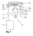
- Fig. 1 shows a metering device 20 according to the invention, which is part of a discharge device 10 shown only schematically.
- the discharge device 10 has a media reservoir 12, which is connected via a feed channel 13 to a first media inlet 32a of the metering device 20.
- a conveyor 11 is provided, which in the present case is an electrically operated pump.
- a storage reservoir 14 is connected, which is designed as a serpentine-like channel and the end 14a is open.
- the discharge device 10 further has a control unit 16, which is provided for controlling the media delivery in the metering device and for controlling the discharge operation.
- This control unit 16 is connected to the conveyor 11 via a signal line 17a. Furthermore, the control unit 16 is connected via a signal line 17b to a vibration device 40 of the metering device 20. A third signal line 17c connects the control unit 16 with an actuating means 70 of the metering device.
- the control unit controls via the signal lines 17a, 17b, the conveyor 11, whose task is the filling of the metering device 20 with medium, and the vibration device 40, whose task is the media discharge from the metering device 20. This occurs as a function of an activation triggered by a user by means of the actuating means 70 and will be explained in more detail below.
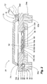
- Fig. 2 shows the metering device 20 of Fig. 1 in a detailed view.
- the metering device has a housing 30, which consists of a housing lower part 32 and a housing upper part 34.
- the locking means 34a in the form of locking lugs the upper housing part 34 is connected to the lower housing part 32.
- an opening 32 c is provided, in which the vibration device 40 is inserted in the form of a Vibrationswandungsabitess 40.
- the opening 32c has a diameter which corresponds approximately to that of the vibration wall section 40.
- 32 system webs 32 d are provided in the lower housing part, on which the vibration wall portion 40 rests, so that it can be removed only from above from the lower housing part 32.
- securing webs 34a are formed, which extend in the direction of the Vibrationswandungsabêts 40 and press it against the contact webs 32d, so that it is completely fixed in the position shown.
- a Auslasswandungsabêt 50 is also the Vibrationswandungsabrough 40 opposite used and held with the upper housing part 34 in unspecified, for example, material or non-positive manner in a designated opening 34b.
- the space between the outlet wall portion 50 and the vibration wall portion forms a metering chamber 60.
- the outlet wall portion 50 is formed as a silicon plate having integrally formed stabilizing ribs 50a extending parallel to the planar extent of the silicon plate on the metering chamber side.
- Recesses 50b which expand in the direction of the metering chamber 60, are arranged between these stabilizing webs 50a.
- metering orifices 62 which are formed as thin openings of the outlet wall section 50, are respectively provided.
- the metering chamber 60 is connected via two medium inlets 60a, 60b to the media reservoir 12 on the one hand and the reservoir 14 on the other.
- the media channel 60a differs from the media channel 60b in that in its course a check valve 62 is provided, which is composed of a valve chamber 64 and a shut-off body 66 arranged in the metering chamber.
- the valve chamber 64 is formed by recesses 32e, 34c, which are provided in the lower part 32 and in the upper part 34.
- the shut-off body 66 is formed as a hollow spherical and elastic body.
- a combined protection and actuation means 70 is provided in the region of the opening 34b.
- This protective and actuating means 70 comprises a protective cap 72, which in a closed in Fig. 2 illustrated state covers the metering openings 62 from the environment.
- a circumferential sealing portion 74 is attached to the cap 72, which rests in the closed state on the housing top 34 and effectively prevents any leakage of medium from the metering device 20 and any entry of contaminants from the outside.
- the protective cap 72 is mounted by means of two axle journals 72a in bearings 34d, which are formed on the upper housing part 34.
- the protective cap 72 can be pivoted about the bearings 74 such that it occupies the dashed end position 72 '. In such a pivoted state, the metering openings 62 are open and allow a discharge of the medium.
- the metering chamber 60, the storage 14 and the intermediate channel sections are filled by means of the conveyor 11 with medium from the media reservoir 12.
- excess media at the end 14a of the storage 14 is released to the environment.
- the end of the conveying process is thus a defined amount of media in the metering chamber 60, the storage reservoir 14 and the channel sections beyond the check valve 63.
- the air located there before the conveying process is partially pushed out of the end 14a of the reservoir 14, partly through the metering 62nd ejected from the metering chamber.
- the stabilizing webs 50a ensure that the air can not escape into a region of the metering chamber 60, from which an outward exit is not possible, but instead is guided reliably to the metering orifices 62.
- the vibration device 40 is activated. Due to their vibrations, the volume in the metering chamber is cyclically increased and decreased at high frequency, with the medium in the metering chamber 60 being forced through the metering orifices 62 where it is supplied to its application as a fine mist.
- the dosing chamber 60 is fed with additional medium from the storage reservoir 14.
- no medium can enter the system through the inlet 32a during the discharge process, since the check valve 63 prevents further inflow.
- the deliverable amount of media is thereby limited to a desired level and is composed of the medium, which is present after filling in the metering chamber 60 and the storage 14 storage.
- the control of the conveyor 11 and the vibration device 40 is effected by the in Fig. 1 illustrated control unit 16, which in turn is connected to a sensor, not shown, within the storage 34d.
- This sensor takes the pivot position of the protective cap 72 true and triggers depending on this pivot position, the various functions.
- the programming of the controller 16 may be configured for different behaviors. For example, a programming is conceivable in which already a slight lifting of the protective cap 72 for triggering the conveyor 11 and thus for filling the metering chamber 60 and the storage memory 14 leads. A triggering of the discharge operation by activation of the vibration device 14 can follow upon reaching the pivot end position 72 '.
- the filling of the metering chamber and the storage memory in the course of closing the protective cap 72, so that the metering chamber and the storage device are filled directly after the use of the discharge.
- Fig. 3 shows a second embodiment of a metering device according to the invention.
- This metering device 120 has a housing 130, which is integrally formed.
- a vibrating wall section 140 is inserted in the metering device 120 in a recess 130c of the housing 130.
- the housing 130 is closed at the top by an outlet wall section 150, in which metering orifices 162 are provided. These metering openings 162 are located in a region above the vibration wall section 140.
- metering chamber 160 Between the vibration wall section 140 and the outlet wall section 150 there is a metering chamber 160, which is surrounded by a circumferential annular channel 168. Between the metering chamber 160 and the annular channel 168, a media feed through an inlet gap 168a is possible over the entire circumference of the vibration wall section 140.
- Fig. 3a shows in enlarged view a section of the Auslasswandungsabêt 150, in which the metering orifices 150c are provided.
- the structure of the outlet wall portion 150 has a support layer 152a which gives stability to the outlet wall portion 150. It may be, for example, a layer of metal or silicon.
- a heating resistor layer 152b is provided on the substrate 152, which can be heated by applying a voltage.
- an electrode layer 152c, an insulator layer 152d, which is preferably formed as a dielectric layer, and a hydrophobic layer 152e are provided on the substrate 152a.
- This layer composite of the outlet wall section 150 has two functions.
- the heating layer 152b allows the outer surface of the outlet wall portion 150 to be heated so as to prevent the formation of a liquid film on the surface and concomitant obstruction to the discharge of the medium.
- the layers 152c, 152d, 152e on the inside of the outlet wall section allow occasional switching of the inner surface between hydrophobic and hydrophilic.
- the surface of the outlet wall portion 150 is hydrophobic on its inside due to the hydrophobic layer 150e. This is achieved by an example silanized surface in the form of the layer 152e. In some cases, however, a hydrophilic behavior of the inner surface can also be achieved by applying a voltage to the electrode 152c.
- Fig. 3b shows the housing 130 and the Vibrationswandungsabites 140 from above, with the Auslasswandungsabrough 150 is removed for clarity. It can be seen that media inlets 160a and 160b for feeding the medium out of the media reservoir and any available storage in the annular channel 168, which completely surrounds the metering chamber and the vibration wall section 140.
- the annular channel 168 provided in operation a media reservoir, which supplies the metering chamber 160 continuously and on all sides with medium during the continuous discharge of the medium. In addition, it is achieved by the inflow possible on all sides that a largely uniform discharge through all metering orifices 160 takes place.
Landscapes
- Measuring Volume Flow (AREA)
- Containers And Packaging Bodies Having A Special Means To Remove Contents (AREA)
- Infusion, Injection, And Reservoir Apparatuses (AREA)
Applications Claiming Priority (1)
| Application Number | Priority Date | Filing Date | Title |
|---|---|---|---|
| DE102006061506A DE102006061506B4 (de) | 2006-12-15 | 2006-12-15 | Dosiervorrichtung |
Publications (2)
| Publication Number | Publication Date |
|---|---|
| EP1932597A2 true EP1932597A2 (fr) | 2008-06-18 |
| EP1932597A3 EP1932597A3 (fr) | 2008-12-17 |
Family
ID=39233009
Family Applications (1)
| Application Number | Title | Priority Date | Filing Date |
|---|---|---|---|
| EP07023942A Withdrawn EP1932597A3 (fr) | 2006-12-15 | 2007-12-11 | Dispositif de dosage |
Country Status (3)
| Country | Link |
|---|---|
| US (1) | US7837129B2 (fr) |
| EP (1) | EP1932597A3 (fr) |
| DE (1) | DE102006061506B4 (fr) |
Cited By (2)
| Publication number | Priority date | Publication date | Assignee | Title |
|---|---|---|---|---|
| EP2165769A3 (fr) * | 2008-09-19 | 2011-11-02 | Ing. Erich Pfeiffer GmbH | Dispositif de distribution |
| US9821125B2 (en) | 2012-04-26 | 2017-11-21 | Koninklijke Philips N.V. | Nebulizer and a method of manufacturing a nebulizer |
Families Citing this family (5)
| Publication number | Priority date | Publication date | Assignee | Title |
|---|---|---|---|---|
| US8439280B2 (en) * | 2007-11-20 | 2013-05-14 | Zobele Holding S.P.A. | Nebulizing device for liquid substances |
| EP2501493B1 (fr) * | 2009-11-18 | 2018-08-22 | Reckitt Benckiser LLC | Dispositif et procédé de traitement de toilettes |
| DE102010024913A1 (de) | 2010-06-15 | 2011-12-15 | Ing. Erich Pfeiffer Gmbh | Zerstäubervorrichtung |
| KR101278532B1 (ko) * | 2010-07-26 | 2013-06-25 | (주)연우 | 휴대용 액상 화장품 전동 미스트 공급기 |
| US12011723B2 (en) | 2019-04-04 | 2024-06-18 | Loesche Gmbh | Lever system for force transmission |
Citations (1)
| Publication number | Priority date | Publication date | Assignee | Title |
|---|---|---|---|---|
| DE102004011726A1 (de) | 2004-03-05 | 2005-09-22 | Ing. Erich Pfeiffer Gmbh | Dosiervorrichtung |
Family Cites Families (17)
| Publication number | Priority date | Publication date | Assignee | Title |
|---|---|---|---|---|
| EP0570609B1 (fr) | 1992-05-20 | 1999-11-03 | International Business Machines Corporation | Procédé pour fabriquer une structure en échelon dans un substrat |
| SG44800A1 (en) * | 1993-12-28 | 1997-12-19 | Westonbridge Int Ltd | A micropump |
| US6142607A (en) | 1996-08-07 | 2000-11-07 | Minolta Co., Ltd. | Ink-jet recording head |
| TW384207B (en) * | 1997-08-20 | 2000-03-11 | Fumakilla Ltd | Piezoelectric chemical-liquid atomizer apparatus and method for repelling or eliminating harmful organism |
| DK0923957T3 (da) * | 1997-11-19 | 2002-02-18 | Microflow Eng Sa | Dyseemne og væskedråbesprøjteindretning til en inhalator egnet til respirationsterapi |
| ES2149748T3 (es) * | 1998-12-01 | 2007-06-16 | Microflow Engineering Sa | Inhalador con nebulizador de ondas ultrasonicas que presenta unas aberturas de boquilla superpuestas sobre las crestas de un patron de onda estacionaria. |
| EP1273355B1 (fr) * | 2001-02-23 | 2010-03-31 | Microflow Engineering SA | Procédé de fabrication d'un nébuliseur de goutelettes et un tel nébuliseur |
| EP1533041A4 (fr) * | 2002-05-08 | 2008-03-19 | Mikuni Kogyo Kk | Dispositif de pulverisation d'eau electrolysee |
| TW532236U (en) * | 2002-06-25 | 2003-05-11 | Wen-Bin Chen | Modular water mist generating device |
| US7208727B2 (en) * | 2003-01-14 | 2007-04-24 | Georgia Tech Research Corporation | Electrospray systems and methods |
| US7312440B2 (en) * | 2003-01-14 | 2007-12-25 | Georgia Tech Research Corporation | Integrated micro fuel processor and flow delivery infrastructure |
| US20040195394A1 (en) * | 2003-02-20 | 2004-10-07 | Valois Sas | Fluid dispenser |
| DE102004006452B4 (de) | 2004-02-05 | 2006-04-20 | Ing. Erich Pfeiffer Gmbh | Mikrodosiervorrichtung |
| FR2868966B1 (fr) * | 2004-04-19 | 2007-08-03 | Brice Lopez | Dispositif de production de micro-gouttes par ejection de liquide et procede de realisation d'un tel dispositif |
| US7178741B2 (en) * | 2004-08-11 | 2007-02-20 | Industrial Technology Research Institute | Micro droplet generator |
| FR2879482B1 (fr) * | 2004-12-20 | 2007-03-30 | Oreal | Dispositif de pulverisation d'un produit, notamment d'un parfum |
| JP2006297226A (ja) * | 2005-04-18 | 2006-11-02 | Sumitomo Electric Ind Ltd | 噴霧器用メッシュノズルおよび噴霧器 |
-
2006
- 2006-12-15 DE DE102006061506A patent/DE102006061506B4/de not_active Expired - Fee Related
-
2007
- 2007-12-11 EP EP07023942A patent/EP1932597A3/fr not_active Withdrawn
- 2007-12-14 US US12/002,329 patent/US7837129B2/en not_active Expired - Fee Related
Patent Citations (1)
| Publication number | Priority date | Publication date | Assignee | Title |
|---|---|---|---|---|
| DE102004011726A1 (de) | 2004-03-05 | 2005-09-22 | Ing. Erich Pfeiffer Gmbh | Dosiervorrichtung |
Cited By (2)
| Publication number | Priority date | Publication date | Assignee | Title |
|---|---|---|---|---|
| EP2165769A3 (fr) * | 2008-09-19 | 2011-11-02 | Ing. Erich Pfeiffer GmbH | Dispositif de distribution |
| US9821125B2 (en) | 2012-04-26 | 2017-11-21 | Koninklijke Philips N.V. | Nebulizer and a method of manufacturing a nebulizer |
Also Published As
| Publication number | Publication date |
|---|---|
| DE102006061506A1 (de) | 2008-06-26 |
| US20090236437A1 (en) | 2009-09-24 |
| DE102006061506B4 (de) | 2008-10-30 |
| EP1932597A3 (fr) | 2008-12-17 |
| US7837129B2 (en) | 2010-11-23 |
Similar Documents
| Publication | Publication Date | Title |
|---|---|---|
| EP1932597A2 (fr) | Dispositif de dosage | |
| DE102009050782B4 (de) | Hohle, Aktuator-getriebene Tröpfchenabgabevorrichtung | |
| DE60101683T2 (de) | Verfahren und vorrichtung zur regelung von flüssigkeitsströmen für eine schwingende atomisiereinrichtung | |
| EP2804504B1 (fr) | Distributeur de fluides | |
| EP3554712B1 (fr) | Tete d'impression pour appliquer un produit de revêtement | |
| DE60117894T2 (de) | Brennstoffeinspritzventil mit einem Piezoelektrischen Aktor | |
| EP0613535B1 (fr) | Soupape micromecanique pour dispositifs de dosage micromecaniques | |
| EP3535063B1 (fr) | Tete d'impression pour appliquer un produit de revêtement sur une piece | |
| DE19946838C1 (de) | Ventil zum Steuern von Flüssigkeiten | |
| EP1799357B1 (fr) | Dispositif de dosage | |
| EP3687699B1 (fr) | Applicateur muni d'une membrane étanche | |
| DE69624642T2 (de) | Pumpenmechanismus | |
| WO2020120176A2 (fr) | Système de dosage et procédé pour commander un système de dosage | |
| EP2065100B1 (fr) | Dispositif de pulvérisation d'agent séparateur pour une machine de coulée | |
| WO2009040165A1 (fr) | Dispositif de microdosage pour doser des quantités infimes d'un produit | |
| EP1817114A1 (fr) | Dispositif de dosage pour au moins une matière | |
| DE102010055019A1 (de) | Vorrichtung zum intermittierenden Auftragen eines flüssigen bis pastösen Mediums auf eine Auftragfläche | |
| EP1447110B1 (fr) | Dispositif de dosage micro | |
| EP4169399B1 (fr) | Distributeur d'un liquide contenant de la nicotine et/ou du cannabis | |
| DE19814532C2 (de) | Spritzpistole zum Auftragen von Beschichtungsmaterialien | |
| EP4039374B1 (fr) | Distributeur pour distribuer des liquides pharmaceutiques | |
| DE202006019724U1 (de) | Vorrichtung mit Schlitzdüsenanordnung zum Abgeben von Fluid | |
| DE10129250A1 (de) | Flüssigkeitsdüse zum breitflächigen Aufbringen einer Flüssigkeitsschicht auf eine Werkstückoberfläche sowie Verfahren zum Betreiben einer solchen | |
| EP1574724B1 (fr) | Micro-soupape pneumatique | |
| DE60002052T2 (de) | Zerstäuber für flüssigkeiten |
Legal Events
| Date | Code | Title | Description |
|---|---|---|---|
| PUAI | Public reference made under article 153(3) epc to a published international application that has entered the european phase |
Free format text: ORIGINAL CODE: 0009012 |
|
| AK | Designated contracting states |
Kind code of ref document: A2 Designated state(s): AT BE BG CH CY CZ DE DK EE ES FI FR GB GR HU IE IS IT LI LT LU LV MC MT NL PL PT RO SE SI SK TR |
|
| AX | Request for extension of the european patent |
Extension state: AL BA HR MK RS |
|
| PUAL | Search report despatched |
Free format text: ORIGINAL CODE: 0009013 |
|
| AK | Designated contracting states |
Kind code of ref document: A3 Designated state(s): AT BE BG CH CY CZ DE DK EE ES FI FR GB GR HU IE IS IT LI LT LU LV MC MT NL PL PT RO SE SI SK TR |
|
| AX | Request for extension of the european patent |
Extension state: AL BA HR MK RS |
|
| 17P | Request for examination filed |
Effective date: 20090512 |
|
| AKX | Designation fees paid |
Designated state(s): AT BE BG CH CY CZ DE DK EE ES FI FR GB GR HU IE IS IT LI LT LU LV MC MT NL PL PT RO SE SI SK TR |
|
| RAP1 | Party data changed (applicant data changed or rights of an application transferred) |
Owner name: APTAR RADOLFZELL GMBH |
|
| 17Q | First examination report despatched |
Effective date: 20121207 |
|
| STAA | Information on the status of an ep patent application or granted ep patent |
Free format text: STATUS: THE APPLICATION IS DEEMED TO BE WITHDRAWN |
|
| 18D | Application deemed to be withdrawn |
Effective date: 20130418 |