EP1932599A1 - Stellantrieb - Google Patents
Stellantrieb Download PDFInfo
- Publication number
- EP1932599A1 EP1932599A1 EP07254739A EP07254739A EP1932599A1 EP 1932599 A1 EP1932599 A1 EP 1932599A1 EP 07254739 A EP07254739 A EP 07254739A EP 07254739 A EP07254739 A EP 07254739A EP 1932599 A1 EP1932599 A1 EP 1932599A1
- Authority
- EP
- European Patent Office
- Prior art keywords
- rod
- actuator
- release
- catch
- plate
- Prior art date
- Legal status (The legal status is an assumption and is not a legal conclusion. Google has not performed a legal analysis and makes no representation as to the accuracy of the status listed.)
- Granted
Links
Images



Classifications
-
- B—PERFORMING OPERATIONS; TRANSPORTING
- B05—SPRAYING OR ATOMISING IN GENERAL; APPLYING FLUENT MATERIALS TO SURFACES, IN GENERAL
- B05C—APPARATUS FOR APPLYING FLUENT MATERIALS TO SURFACES, IN GENERAL
- B05C17/00—Hand tools or apparatus using hand held tools, for applying liquids or other fluent materials to, for spreading applied liquids or other fluent materials on, or for partially removing applied liquids or other fluent materials from, surfaces
- B05C17/005—Hand tools or apparatus using hand held tools, for applying liquids or other fluent materials to, for spreading applied liquids or other fluent materials on, or for partially removing applied liquids or other fluent materials from, surfaces for discharging material from a reservoir or container located in or on the hand tool through an outlet orifice by pressure without using surface contacting members like pads or brushes
- B05C17/01—Hand tools or apparatus using hand held tools, for applying liquids or other fluent materials to, for spreading applied liquids or other fluent materials on, or for partially removing applied liquids or other fluent materials from, surfaces for discharging material from a reservoir or container located in or on the hand tool through an outlet orifice by pressure without using surface contacting members like pads or brushes with manually mechanically or electrically actuated piston or the like
- B05C17/0116—Hand tools or apparatus using hand held tools, for applying liquids or other fluent materials to, for spreading applied liquids or other fluent materials on, or for partially removing applied liquids or other fluent materials from, surfaces for discharging material from a reservoir or container located in or on the hand tool through an outlet orifice by pressure without using surface contacting members like pads or brushes with manually mechanically or electrically actuated piston or the like characterised by the piston driving means
- B05C17/012—Stepwise advancing mechanism, e.g. pawl and ratchets
- B05C17/0123—Lever actuated
-
- Y—GENERAL TAGGING OF NEW TECHNOLOGICAL DEVELOPMENTS; GENERAL TAGGING OF CROSS-SECTIONAL TECHNOLOGIES SPANNING OVER SEVERAL SECTIONS OF THE IPC; TECHNICAL SUBJECTS COVERED BY FORMER USPC CROSS-REFERENCE ART COLLECTIONS [XRACs] AND DIGESTS
- Y10—TECHNICAL SUBJECTS COVERED BY FORMER USPC
- Y10T—TECHNICAL SUBJECTS COVERED BY FORMER US CLASSIFICATION
- Y10T74/00—Machine element or mechanism
- Y10T74/15—Intermittent grip type mechanical movement
- Y10T74/1526—Oscillation or reciprocation to intermittent unidirectional motion
- Y10T74/1553—Lever actuator
Definitions
- This invention relates to an actuator for advancing a rod.
- An actuator advancing a rod is used, for example, in a dispensing appliance for dispensing viscous materials such as mastic caulking material.
- Viscous material such as mastic caulking material
- a cartridge having a discharge nozzle The cartridge can be mounted in a dispensing appliance, often called a dispensing gun.
- a dispensing gun An example of such a dispensing gun is described in British Patent GB 1555455 .
- the gun has a plunger or push rod slidably mounted in a stock.
- the cartridge is mounted in a keep before the plunger which is advanced by means of a catch plate engaging the rod by means of a trigger lever to force a piston, inside one end of the cartridge, forward to urge the material from the nozzle at the other end.
- the trigger and catch plate are reset at the end of a dispensing stroke and the dispensing force can be reapplied.
- the plunger is held against the piston in the cartridge between trigger strokes by means of a locking plate.
- the gun is entirely acceptable as a dispensing tool for viscous material in many situations.
- the body of the cartridge expands radially under a dispensing force.
- any pockets of gas are trapped in the cartridge they will compress during discharge of the material and expand once the dispensing force is removed.
- the plunger is maintained by the locking plate substantially in the position at which the dispensing force was removed from the trigger, the contracting cartridge and any expanding pocket of gas tends to cause continued dispensing of material when it is not required unless the locking plate is released manually to retreat the rod. It is sometimes desirable to be able halt the discharge immediately the hand releases the trigger.
- EP-B-0448375 discloses a pressure relief device whereby the rod is automatically retreated at the end of a trigger stroke (that is when force is released from the trigger) by a small amount to prevent the mastic from continuing to be dispensed.
- the mechanism works well as a modification of a conventional type of dispensing gun in GB 1555455 for certain situations.
- an actuator for advancing a rod comprises a stock defining a channel for the rod, a catch plate member engageable with the rod, a trigger member for moving the catch member to engage and advance the rod in one direction, a release member engageable with the rod to prevent the rod from retreating in the other direction, and transmission means for transmitting a relieving force applied to the release member to the catch member to urge the catch member from engagement with the rod, thereby enabling the rod to be retreated wherein the transmission means are arranged to move with the rod so the release member moves to and from the engaged relationship with the rod.
- the release member may be arranged to move with the rod to an engaged attitude with respect to the rod as the rod is retreated, thereafter preventing further retreat of the rod.
- the release member may be arranged to move with the rod to a released attitude as the rod is initially advanced.
- the release plate may be arranged to be pivotable between the releasing and engaged relationships with the rod.
- the transmission member may be a sleeve or other member arranged alongside the rod and extending between the release member and the catch member. In some embodiments the transmission means may be attached to the release member.
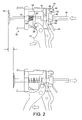
- FIG. 1 shows a mastic gun for dispensing viscous materials, such as mastic, for example a caulking or sealing material.
- the gun comprises a stock 10 defining a pair of aligned holes 12/14 carrying a drive rod 16.
- the rod 16 is terminated at a front end in a plunger 18.
- the stock 10 also has a keep or yoke 19 (only the rear arms of which are shown) mounted on the front for holding a cartridge of material to be dispensed from a nozzle by application of a force to the plunger as the rod is advanced.
- a stock 10 is also formed with a downwardly depending fixed handle or butt 20 which is complemented by a trigger lever 22 pivotably mounted on the stock about an axis which is transverse to the axis of the drive rod 16.
- a catch plate 24 has a through hole 26 by which it rides on the rod 16. A lower part of the catch plate 24 engages a transverse cross member 28 which is mounted on the trigger lever 22 above its pivot point.
- a spring 30 is mounted on the rod 16 in front of the catch plate 24. The spring is braced against a forward wall of the stop 10 and exerts a force on a catch plate 24 to bias it into an engaged or biting attitude with respect to the rod.
- the catch plate 24 In this engaged attitude with respect to the rod, the catch plate 24 has an upper rear edge and a lower forward edge of that part of the catch plate defining its hole 26 which bite on the rod so that the force applied to the trigger lever 22 is transmitted through the catch plate and translated into linear forward movement to the rod through the holes 12/14 formed in the stock, thereby performing a dispensing action by pressing the plunger onto the back of a piston in the cartridge held in the yoke (not shown).
- a sleeve 40 is also mounted on the rod 16 and is free to slide in the hole 14.
- the sleeve 40 passes through the hole 14 for the rod 16 and acts as a movable bush for the rod at the rear end of the stock.
- the sleeve 40 is held to move with a release plate 42 also mounted on the rod by means of its own through hole (not shown).
- the sleeve 40 and the release plate 42 are held together by means of a plastics jaw 46 which engages a circular flange (not shown) on one end of the sleeve 40 and receives the release plate 42 within its body. The sleeve 40 is thus carried with the movement of the release plate 42 by the jaw.
- Fig.3 The rear of the actuator is shown in Fig.3 which also shows the complete applicator.
- An upper end 48 of the release plate acts between front and rear noses 50/52.
- a released or upright attitude of the release plate is defined between the forward nose 50 and a lower projection 54 extending rearwardly from the back of the stock beneath the rod.
- a braking or canted attitude of the release plate is defined between the rear nose 52and the biting engagement of the part of the plate defining its through hole 56 for the rod
- Figure 1 shows the actuator at the start of a stroke of the trigger lever 22.
- the trigger lever 22 is forwardly extended.
- the catch plate 24 is engaged with the rod 16 because it is biased into that attitude by the spring 30.
- the release plate 42 is riding on the rod 16 together with the sleeve 40.
- the trigger As the trigger is squeezed on the rearwardly biased catch plate, it exerts a force on the lower part of the catch plate. As the catch plate is already forced into engagement with the rod by the force of the spring 30, the force applied to the trigger lever is immediately translated into forward movement of the rod.
- the rod carries the release plate 42 to its position shown in Figure 2 and is then allowed to run past the release plate. However, the release plate is carried to the upright or released attitude with respect to the rod shown in Figure 2 wherein it is engaging the forward nose 50 and the projection 54 on the stock 10. Eventually, the trigger is moved through a full stroke (or part of a stroke) and is in the position shown in Figure 2 . Here it will be seen that the spring 30 has been compressed in front of the advanced catch plate 24.
- the actuator Upon release of the trigger lever, the actuator assumes the arrangement shown in Figure 1 again.
- the lower part of the catch plate 24 is braced against the cross member 28 by the force of the spring, thereby assuming an engaged relationship with the rod.
- the catch plate has slid backwards over the arrested rod in the upright attitude defined by the face of the spring.
- the release plate is carried backwards with the rod to an engaged relationship with the rod whereby it is engaged with the rear nose 52 and away from the projection 54.
- the attitude of the release plate has been changed such that the forward upper edge and a rear lower edge of the part of the release plate defining the hole are engaged with the rod by biting on it so that it can move no further rearwardly. From releasing the force on the trigger lever the rod is able to retreat that small distance defined between the two (released and engaged) attitudes of the release plate, under the force exerted by any expanding gas in the cartridge or radial shrinkage of the cartridge itself.
- Figure 4 illustrates the situation in which the actuator is made ready to retreat the rod, for example to pull it manually as far back as possible in order to remove an empty cartridge and/or insert a cartridge into the yoke.
- a forward pressure is applied to the bottom of the release plate 42 such that the release plate assumes the released or upright attitude with respect to the rod and no edges of the release plate defining its hole are biting on the rod.
- This movement of the release plate enabling the rod to slide freely is transmitted by the sleeve 40 to the catch plate 24 so that it too is urged into an upright disengaged relationship slightly forward of its engaged relationship.
- the force applied through the sleeve moves the catch plate upright and away from the cross member 28 against the force of the spring.
- the actuator disclosed requires only a single spring, i.e. that to bias the catch plate, and uses an advantageous connection with the release plate both to transmit the releasing force applied to the release plate and to create a frictional engagement whereby the release plate can ride between its two positions of engagement and release from the rod.
- the parts of the actuator can be made of metal or plastics.
- the plates are steel, the stock and the trigger lever are cast aluminium/zinc or a suitably rigid plastics such as polypropylene, glass filled nylon or ABS.
- the rod is made of steel. It can be round, hexagonal or any other shape in section. While the engagement by the plates on the rod includes the use of through holes in the plates, it can equally well be by means of open slots as long as the plates define engaging parts which bite on the rod when engaging it either to drive the rod forward or prevent it from retreating.
- the sleeve for transmitting the force applied to the release plate to the catch plate could equally well be any other member extending between the two.
- a member or members extending alongside the rod 16 could transmit the forces between the two plates.
- the collar and the sleeve (or some other device) can be separate pieces or a single plastics moulding.
- the release plate has to be free enough within the collar to move between its two attitudes.
- the release plate can be biased to its engaged position by a spring.
- advance of the rod causes very small forward movement of the release plate from the engaged position, but is the same in its effect.
- the release plate is depressed as before against the projection 54.
Landscapes
- Engineering & Computer Science (AREA)
- Mechanical Engineering (AREA)
- Coating Apparatus (AREA)
- Valve Device For Special Equipments (AREA)
- Fluid-Driven Valves (AREA)
- Actuator (AREA)
- Braking Arrangements (AREA)
Applications Claiming Priority (1)
| Application Number | Priority Date | Filing Date | Title |
|---|---|---|---|
| GBGB0624709.2A GB0624709D0 (en) | 2006-12-11 | 2006-12-11 | Actuator |
Publications (2)
| Publication Number | Publication Date |
|---|---|
| EP1932599A1 true EP1932599A1 (de) | 2008-06-18 |
| EP1932599B1 EP1932599B1 (de) | 2010-08-04 |
Family
ID=37711926
Family Applications (1)
| Application Number | Title | Priority Date | Filing Date |
|---|---|---|---|
| EP07254739A Active EP1932599B1 (de) | 2006-12-11 | 2007-12-07 | Stellantrieb |
Country Status (8)
| Country | Link |
|---|---|
| US (1) | US7959039B2 (de) |
| EP (1) | EP1932599B1 (de) |
| JP (1) | JP5356673B2 (de) |
| AT (1) | ATE476263T1 (de) |
| AU (1) | AU2007237171B2 (de) |
| DE (1) | DE602007008191D1 (de) |
| ES (1) | ES2350124T3 (de) |
| GB (1) | GB0624709D0 (de) |
Cited By (2)
| Publication number | Priority date | Publication date | Assignee | Title |
|---|---|---|---|---|
| DE102011004971A1 (de) * | 2011-03-02 | 2012-09-06 | Hilti Aktiengesellschaft | Auspressgerät |
| NO343787B1 (en) * | 2018-02-16 | 2019-06-11 | Norwegian Tool Company As | Handheld jacking tool and strapping system |
Families Citing this family (14)
| Publication number | Priority date | Publication date | Assignee | Title |
|---|---|---|---|---|
| DE102006035476A1 (de) * | 2006-12-04 | 2008-06-05 | Hilti Ag | Auspressgerät |
| USD619863S1 (en) * | 2009-08-04 | 2010-07-20 | Po-Jen Shih | Sealant gun |
| CN101879491B (zh) * | 2010-08-17 | 2012-10-24 | 天津市金锚集团有限责任公司 | 胶枪进给装置及其限位构造 |
| CN101905211B (zh) * | 2010-08-17 | 2012-10-03 | 天津市金锚集团有限责任公司 | 具有限位构造和把套组件的胶枪进给装置 |
| DE102011003236A1 (de) * | 2011-01-27 | 2015-03-26 | Hilti Aktiengesellschaft | Auspressgerät |
| US8985403B2 (en) | 2013-03-15 | 2015-03-24 | Patent & Investment Llc | Lightweight applicator system for efficient extrusive dispensing of work material |
| TWI564088B (zh) * | 2013-06-21 | 2017-01-01 | Huang-Cheng Ye | Lightly strengthen the structure of the fight |
| GB2530476A (en) | 2014-07-15 | 2016-03-30 | Cox Ltd | Multicomponent dispenser |
| DE202019101933U1 (de) * | 2018-06-07 | 2019-04-11 | Zhejiang Volcano Machinery Co., Ltd. | Auspresspistole |
| USD885151S1 (en) * | 2018-11-07 | 2020-05-26 | Dripless, Inc. | Caulking gun |
| US11060657B1 (en) * | 2020-02-14 | 2021-07-13 | Recor Outdoors, LLC | Telescoping support stand for a user-operated device |
| USD1013471S1 (en) * | 2021-07-05 | 2024-02-06 | Altachem Nv | Caulking implement |
| US12410041B2 (en) | 2021-10-25 | 2025-09-09 | Stanley Black & Decker, Inc. | Lifting and lowering tool |
| USD1103724S1 (en) * | 2024-04-18 | 2025-12-02 | Eric Okyere | Caulking gun |
Citations (6)
| Publication number | Priority date | Publication date | Assignee | Title |
|---|---|---|---|---|
| GB1555455A (en) | 1976-06-11 | 1979-11-07 | Cox Mastic Appliances Ltd P C | Dispensing gun |
| US5370282A (en) | 1992-09-19 | 1994-12-06 | Hilti Aktiengesellschaft | Advancing mechanism for a dispensing tool |
| EP0448375B1 (de) | 1990-03-22 | 1995-05-31 | Bba Group Plc. | Ausgabepistole |
| EP1063019A2 (de) | 1999-06-22 | 2000-12-27 | P.C. Cox (Newbury) Limited | Betätigungsgetriebe für eine Schubstange |
| WO2002083325A1 (en) * | 2001-04-10 | 2002-10-24 | Ian Alexander Durrant | Dispensing gun |
| US7011238B1 (en) * | 2005-09-14 | 2006-03-14 | Kent Bridge Enterprise Co., Ltd. | Adjustable caulk dispensing gun |
Family Cites Families (23)
| Publication number | Priority date | Publication date | Assignee | Title |
|---|---|---|---|---|
| US2732102A (en) * | 1956-01-24 | ekins | ||
| US4033484A (en) * | 1975-03-26 | 1977-07-05 | Ornsteen Chemicals, Inc. | Hot melt cartridge adhesive gun |
| US4072254A (en) * | 1976-07-07 | 1978-02-07 | P.C. Cox (Mastic Appliances) Limited | Dispensing guns |
| AU541325B2 (en) * | 1979-04-10 | 1985-01-03 | Wellcome Foundation Limited, The | Dose dispensing of pastes |
| US4509662A (en) * | 1983-01-13 | 1985-04-09 | Weiss Sherman L | Caulking gun |
| US4572409A (en) | 1983-05-02 | 1986-02-25 | Gary Finnegan | Drip free caulking gun |
| JPS6168161A (ja) * | 1984-09-08 | 1986-04-08 | Semedain Kk | 粘着性材料押出装置におけるたれ防止装置 |
| GB8506010D0 (en) | 1985-03-08 | 1985-04-11 | Ici Plc | Extrusion apparatus |
| US4706853A (en) * | 1986-01-13 | 1987-11-17 | Stonesifer Gerald M | Caulking gun with means to prevent rotation of compound cartridge during use and to provide positive pressure release |
| US5529225A (en) * | 1994-03-04 | 1996-06-25 | Chang; Peter J. | Constricted spring pressure relief mechanism for dripless drive caulk dispensing devices |
| US5823403A (en) * | 1996-01-17 | 1998-10-20 | Albion Engineering Company | High thrust drive system and devices employing |
| US5887765A (en) * | 1996-08-16 | 1999-03-30 | Dripless, Inc. | Caulk gun |
| CN1124906C (zh) | 1998-01-23 | 2003-10-22 | 伊昂·亚历山大·杜让脱 | 改进的分配枪 |
| US6155463A (en) * | 1998-10-27 | 2000-12-05 | Z-Pro International, Inc. | Viscous material dispenser |
| US6176398B1 (en) | 1999-09-30 | 2001-01-23 | Peter J. Chang | Effective trigger grip power device for caulk dispensing devices |
| US6286729B1 (en) * | 2000-11-17 | 2001-09-11 | Kae Chih Enterprise Co., Ltd. | Feeding device for a caulking gun |
| US6691899B2 (en) * | 2002-07-03 | 2004-02-17 | Kent Bridge Enterprise Co., Ltd. | Dispensing gun having pressure relieving device |
| JP4156310B2 (ja) * | 2002-09-12 | 2008-09-24 | 株式会社山本製作所 | コーキングガン |
| CN2612468Y (zh) * | 2003-04-16 | 2004-04-21 | 李�杰 | 改进的框架式挤胶枪 |
| US20050006414A1 (en) * | 2003-06-27 | 2005-01-13 | Yu-Chun Tseng | Extruding implement structure |
| US7073691B2 (en) | 2003-07-31 | 2006-07-11 | Danny Rumrill | Caulking gun |
| GB0616793D0 (en) * | 2006-08-24 | 2006-10-04 | Cox Ltd | Dispensing apparatus |
| US20080197155A1 (en) * | 2007-02-20 | 2008-08-21 | Chen Chien Liang | Structure of a glue gun |
-
2006
- 2006-12-11 GB GBGB0624709.2A patent/GB0624709D0/en not_active Ceased
-
2007
- 2007-11-26 AU AU2007237171A patent/AU2007237171B2/en not_active Ceased
- 2007-12-07 EP EP07254739A patent/EP1932599B1/de active Active
- 2007-12-07 AT AT07254739T patent/ATE476263T1/de not_active IP Right Cessation
- 2007-12-07 DE DE602007008191T patent/DE602007008191D1/de active Active
- 2007-12-07 ES ES07254739T patent/ES2350124T3/es active Active
- 2007-12-11 US US12/001,280 patent/US7959039B2/en active Active
- 2007-12-11 JP JP2007320086A patent/JP5356673B2/ja not_active Expired - Fee Related
Patent Citations (6)
| Publication number | Priority date | Publication date | Assignee | Title |
|---|---|---|---|---|
| GB1555455A (en) | 1976-06-11 | 1979-11-07 | Cox Mastic Appliances Ltd P C | Dispensing gun |
| EP0448375B1 (de) | 1990-03-22 | 1995-05-31 | Bba Group Plc. | Ausgabepistole |
| US5370282A (en) | 1992-09-19 | 1994-12-06 | Hilti Aktiengesellschaft | Advancing mechanism for a dispensing tool |
| EP1063019A2 (de) | 1999-06-22 | 2000-12-27 | P.C. Cox (Newbury) Limited | Betätigungsgetriebe für eine Schubstange |
| WO2002083325A1 (en) * | 2001-04-10 | 2002-10-24 | Ian Alexander Durrant | Dispensing gun |
| US7011238B1 (en) * | 2005-09-14 | 2006-03-14 | Kent Bridge Enterprise Co., Ltd. | Adjustable caulk dispensing gun |
Cited By (3)
| Publication number | Priority date | Publication date | Assignee | Title |
|---|---|---|---|---|
| DE102011004971A1 (de) * | 2011-03-02 | 2012-09-06 | Hilti Aktiengesellschaft | Auspressgerät |
| NO343787B1 (en) * | 2018-02-16 | 2019-06-11 | Norwegian Tool Company As | Handheld jacking tool and strapping system |
| NO20180251A1 (en) * | 2018-02-16 | 2019-06-11 | Norwegian Tool Company As | Handheld jacking tool and strapping system |
Also Published As
| Publication number | Publication date |
|---|---|
| ES2350124T3 (es) | 2011-01-18 |
| US20080179351A1 (en) | 2008-07-31 |
| ATE476263T1 (de) | 2010-08-15 |
| JP2008142712A (ja) | 2008-06-26 |
| US7959039B2 (en) | 2011-06-14 |
| AU2007237171B2 (en) | 2011-10-06 |
| DE602007008191D1 (de) | 2010-09-16 |
| JP5356673B2 (ja) | 2013-12-04 |
| GB0624709D0 (en) | 2007-01-17 |
| EP1932599B1 (de) | 2010-08-04 |
| AU2007237171A1 (en) | 2008-06-26 |
Similar Documents
| Publication | Publication Date | Title |
|---|---|---|
| EP1932599B1 (de) | Stellantrieb | |
| US7980428B2 (en) | Viscous material dispensing apparatus with brake | |
| CA2038795C (en) | Dispensing gun | |
| US6155463A (en) | Viscous material dispenser | |
| CN100490991C (zh) | 具有胶筒保持件的压胶枪 | |
| US6691899B2 (en) | Dispensing gun having pressure relieving device | |
| US10016781B2 (en) | Caulking gun | |
| US5934506A (en) | Caulking gun and cartridge with afterflow prevention | |
| US20100237105A1 (en) | Viscous Material Dispenser | |
| EP0776301B1 (de) | Pistole für dichtungsmaterial und patrone mit leckverhinderung | |
| DE102009007116A1 (de) | Behälter mit Ventil | |
| EP2445652B1 (de) | Spannwerkzeug in form einer kartuschenausdrückvorrichtung | |
| US20040124215A1 (en) | Dispenser for limiting material extruded after actuation | |
| EP3515607B1 (de) | Abdichtungspistolen | |
| EP1063019A2 (de) | Betätigungsgetriebe für eine Schubstange | |
| WO2001010744A1 (en) | Decompressing system for a masticating gun | |
| GB2358676A (en) | Caulking gun with pressure-relief device for drip-free operation | |
| WO2002083325A1 (en) | Dispensing gun |
Legal Events
| Date | Code | Title | Description |
|---|---|---|---|
| PUAI | Public reference made under article 153(3) epc to a published international application that has entered the european phase |
Free format text: ORIGINAL CODE: 0009012 |
|
| AK | Designated contracting states |
Kind code of ref document: A1 Designated state(s): AT BE BG CH CY CZ DE DK EE ES FI FR GB GR HU IE IS IT LI LT LU LV MC MT NL PL PT RO SE SI SK TR |
|
| AX | Request for extension of the european patent |
Extension state: AL BA HR MK RS |
|
| 17P | Request for examination filed |
Effective date: 20081216 |
|
| AKX | Designation fees paid |
Designated state(s): AT BE BG CH CY CZ DE DK EE ES FI FR GB GR HU IE IS IT LI LT LU LV MC MT NL PL PT RO SE SI SK TR |
|
| 17Q | First examination report despatched |
Effective date: 20090416 |
|
| GRAP | Despatch of communication of intention to grant a patent |
Free format text: ORIGINAL CODE: EPIDOSNIGR1 |
|
| RAP1 | Party data changed (applicant data changed or rights of an application transferred) |
Owner name: P.C. COX LIMITED |
|
| GRAS | Grant fee paid |
Free format text: ORIGINAL CODE: EPIDOSNIGR3 |
|
| GRAA | (expected) grant |
Free format text: ORIGINAL CODE: 0009210 |
|
| AK | Designated contracting states |
Kind code of ref document: B1 Designated state(s): AT BE BG CH CY CZ DE DK EE ES FI FR GB GR HU IE IS IT LI LT LU LV MC MT NL PL PT RO SE SI SK TR |
|
| REG | Reference to a national code |
Ref country code: GB Ref legal event code: FG4D |
|
| REG | Reference to a national code |
Ref country code: CH Ref legal event code: EP |
|
| REG | Reference to a national code |
Ref country code: IE Ref legal event code: FG4D |
|
| REF | Corresponds to: |
Ref document number: 602007008191 Country of ref document: DE Date of ref document: 20100916 Kind code of ref document: P |
|
| REG | Reference to a national code |
Ref country code: NL Ref legal event code: T3 |
|
| REG | Reference to a national code |
Ref country code: ES Ref legal event code: FG2A Effective date: 20110105 |
|
| LTIE | Lt: invalidation of european patent or patent extension |
Effective date: 20100804 |
|
| PG25 | Lapsed in a contracting state [announced via postgrant information from national office to epo] |
Ref country code: FI Free format text: LAPSE BECAUSE OF FAILURE TO SUBMIT A TRANSLATION OF THE DESCRIPTION OR TO PAY THE FEE WITHIN THE PRESCRIBED TIME-LIMIT Effective date: 20100804 Ref country code: LT Free format text: LAPSE BECAUSE OF FAILURE TO SUBMIT A TRANSLATION OF THE DESCRIPTION OR TO PAY THE FEE WITHIN THE PRESCRIBED TIME-LIMIT Effective date: 20100804 Ref country code: AT Free format text: LAPSE BECAUSE OF FAILURE TO SUBMIT A TRANSLATION OF THE DESCRIPTION OR TO PAY THE FEE WITHIN THE PRESCRIBED TIME-LIMIT Effective date: 20100804 |
|
| PG25 | Lapsed in a contracting state [announced via postgrant information from national office to epo] |
Ref country code: IS Free format text: LAPSE BECAUSE OF FAILURE TO SUBMIT A TRANSLATION OF THE DESCRIPTION OR TO PAY THE FEE WITHIN THE PRESCRIBED TIME-LIMIT Effective date: 20101204 Ref country code: PL Free format text: LAPSE BECAUSE OF FAILURE TO SUBMIT A TRANSLATION OF THE DESCRIPTION OR TO PAY THE FEE WITHIN THE PRESCRIBED TIME-LIMIT Effective date: 20100804 Ref country code: PT Free format text: LAPSE BECAUSE OF FAILURE TO SUBMIT A TRANSLATION OF THE DESCRIPTION OR TO PAY THE FEE WITHIN THE PRESCRIBED TIME-LIMIT Effective date: 20101206 Ref country code: SI Free format text: LAPSE BECAUSE OF FAILURE TO SUBMIT A TRANSLATION OF THE DESCRIPTION OR TO PAY THE FEE WITHIN THE PRESCRIBED TIME-LIMIT Effective date: 20100804 Ref country code: BG Free format text: LAPSE BECAUSE OF FAILURE TO SUBMIT A TRANSLATION OF THE DESCRIPTION OR TO PAY THE FEE WITHIN THE PRESCRIBED TIME-LIMIT Effective date: 20101104 Ref country code: CY Free format text: LAPSE BECAUSE OF FAILURE TO SUBMIT A TRANSLATION OF THE DESCRIPTION OR TO PAY THE FEE WITHIN THE PRESCRIBED TIME-LIMIT Effective date: 20100804 |
|
| PG25 | Lapsed in a contracting state [announced via postgrant information from national office to epo] |
Ref country code: LV Free format text: LAPSE BECAUSE OF FAILURE TO SUBMIT A TRANSLATION OF THE DESCRIPTION OR TO PAY THE FEE WITHIN THE PRESCRIBED TIME-LIMIT Effective date: 20100804 Ref country code: SE Free format text: LAPSE BECAUSE OF FAILURE TO SUBMIT A TRANSLATION OF THE DESCRIPTION OR TO PAY THE FEE WITHIN THE PRESCRIBED TIME-LIMIT Effective date: 20100804 Ref country code: BE Free format text: LAPSE BECAUSE OF FAILURE TO SUBMIT A TRANSLATION OF THE DESCRIPTION OR TO PAY THE FEE WITHIN THE PRESCRIBED TIME-LIMIT Effective date: 20100804 Ref country code: GR Free format text: LAPSE BECAUSE OF FAILURE TO SUBMIT A TRANSLATION OF THE DESCRIPTION OR TO PAY THE FEE WITHIN THE PRESCRIBED TIME-LIMIT Effective date: 20101105 |
|
| PG25 | Lapsed in a contracting state [announced via postgrant information from national office to epo] |
Ref country code: DK Free format text: LAPSE BECAUSE OF FAILURE TO SUBMIT A TRANSLATION OF THE DESCRIPTION OR TO PAY THE FEE WITHIN THE PRESCRIBED TIME-LIMIT Effective date: 20100804 |
|
| PG25 | Lapsed in a contracting state [announced via postgrant information from national office to epo] |
Ref country code: RO Free format text: LAPSE BECAUSE OF FAILURE TO SUBMIT A TRANSLATION OF THE DESCRIPTION OR TO PAY THE FEE WITHIN THE PRESCRIBED TIME-LIMIT Effective date: 20100804 Ref country code: EE Free format text: LAPSE BECAUSE OF FAILURE TO SUBMIT A TRANSLATION OF THE DESCRIPTION OR TO PAY THE FEE WITHIN THE PRESCRIBED TIME-LIMIT Effective date: 20100804 Ref country code: CZ Free format text: LAPSE BECAUSE OF FAILURE TO SUBMIT A TRANSLATION OF THE DESCRIPTION OR TO PAY THE FEE WITHIN THE PRESCRIBED TIME-LIMIT Effective date: 20100804 Ref country code: SK Free format text: LAPSE BECAUSE OF FAILURE TO SUBMIT A TRANSLATION OF THE DESCRIPTION OR TO PAY THE FEE WITHIN THE PRESCRIBED TIME-LIMIT Effective date: 20100804 |
|
| PLBE | No opposition filed within time limit |
Free format text: ORIGINAL CODE: 0009261 |
|
| STAA | Information on the status of an ep patent application or granted ep patent |
Free format text: STATUS: NO OPPOSITION FILED WITHIN TIME LIMIT |
|
| 26N | No opposition filed |
Effective date: 20110506 |
|
| PG25 | Lapsed in a contracting state [announced via postgrant information from national office to epo] |
Ref country code: MC Free format text: LAPSE BECAUSE OF NON-PAYMENT OF DUE FEES Effective date: 20101231 |
|
| REG | Reference to a national code |
Ref country code: DE Ref legal event code: R097 Ref document number: 602007008191 Country of ref document: DE Effective date: 20110506 |
|
| PG25 | Lapsed in a contracting state [announced via postgrant information from national office to epo] |
Ref country code: IE Free format text: LAPSE BECAUSE OF NON-PAYMENT OF DUE FEES Effective date: 20101207 |
|
| PG25 | Lapsed in a contracting state [announced via postgrant information from national office to epo] |
Ref country code: IT Free format text: LAPSE BECAUSE OF NON-PAYMENT OF DUE FEES Effective date: 20101207 Ref country code: MT Free format text: LAPSE BECAUSE OF FAILURE TO SUBMIT A TRANSLATION OF THE DESCRIPTION OR TO PAY THE FEE WITHIN THE PRESCRIBED TIME-LIMIT Effective date: 20100804 |
|
| REG | Reference to a national code |
Ref country code: CH Ref legal event code: PL |
|
| PG25 | Lapsed in a contracting state [announced via postgrant information from national office to epo] |
Ref country code: HU Free format text: LAPSE BECAUSE OF FAILURE TO SUBMIT A TRANSLATION OF THE DESCRIPTION OR TO PAY THE FEE WITHIN THE PRESCRIBED TIME-LIMIT Effective date: 20110205 Ref country code: LU Free format text: LAPSE BECAUSE OF NON-PAYMENT OF DUE FEES Effective date: 20101207 |
|
| PG25 | Lapsed in a contracting state [announced via postgrant information from national office to epo] |
Ref country code: LI Free format text: LAPSE BECAUSE OF NON-PAYMENT OF DUE FEES Effective date: 20111231 Ref country code: CH Free format text: LAPSE BECAUSE OF NON-PAYMENT OF DUE FEES Effective date: 20111231 Ref country code: TR Free format text: LAPSE BECAUSE OF FAILURE TO SUBMIT A TRANSLATION OF THE DESCRIPTION OR TO PAY THE FEE WITHIN THE PRESCRIBED TIME-LIMIT Effective date: 20100804 |
|
| REG | Reference to a national code |
Ref country code: FR Ref legal event code: PLFP Year of fee payment: 9 |
|
| REG | Reference to a national code |
Ref country code: DE Ref legal event code: R082 Ref document number: 602007008191 Country of ref document: DE Representative=s name: MANITZ FINSTERWALD PATENT- UND RECHTSANWALTSPA, DE Ref country code: DE Ref legal event code: R082 Ref document number: 602007008191 Country of ref document: DE Representative=s name: MANITZ, FINSTERWALD & PARTNER GBR, DE Ref country code: DE Ref legal event code: R082 Ref document number: 602007008191 Country of ref document: DE Representative=s name: MANITZ FINSTERWALD PATENTANWAELTE PARTMBB, DE |
|
| REG | Reference to a national code |
Ref country code: FR Ref legal event code: PLFP Year of fee payment: 10 |
|
| REG | Reference to a national code |
Ref country code: FR Ref legal event code: PLFP Year of fee payment: 11 |
|
| PGFP | Annual fee paid to national office [announced via postgrant information from national office to epo] |
Ref country code: NL Payment date: 20171219 Year of fee payment: 11 |
|
| PGFP | Annual fee paid to national office [announced via postgrant information from national office to epo] |
Ref country code: IT Payment date: 20171221 Year of fee payment: 11 |
|
| REG | Reference to a national code |
Ref country code: DE Ref legal event code: R081 Ref document number: 602007008191 Country of ref document: DE Owner name: MEDMIX SWITZERLAND AG, CH Free format text: FORMER OWNER: P C COX LTD., NEWBURY, BERKSHIRE, GB Ref country code: DE Ref legal event code: R082 Ref document number: 602007008191 Country of ref document: DE Representative=s name: MANITZ FINSTERWALD PATENT- UND RECHTSANWALTSPA, DE Ref country code: DE Ref legal event code: R082 Ref document number: 602007008191 Country of ref document: DE Representative=s name: MANITZ FINSTERWALD PATENTANWAELTE PARTMBB, DE Ref country code: DE Ref legal event code: R081 Ref document number: 602007008191 Country of ref document: DE Owner name: SULZER MIXPAC AG, CH Free format text: FORMER OWNER: P C COX LTD., NEWBURY, BERKSHIRE, GB |
|
| REG | Reference to a national code |
Ref country code: ES Ref legal event code: PC2A Owner name: SULZER MIXPAC AG Effective date: 20190516 |
|
| REG | Reference to a national code |
Ref country code: GB Ref legal event code: 732E Free format text: REGISTERED BETWEEN 20190516 AND 20190522 |
|
| REG | Reference to a national code |
Ref country code: NL Ref legal event code: MM Effective date: 20190101 |
|
| PG25 | Lapsed in a contracting state [announced via postgrant information from national office to epo] |
Ref country code: NL Free format text: LAPSE BECAUSE OF NON-PAYMENT OF DUE FEES Effective date: 20190101 |
|
| PG25 | Lapsed in a contracting state [announced via postgrant information from national office to epo] |
Ref country code: IT Free format text: LAPSE BECAUSE OF NON-PAYMENT OF DUE FEES Effective date: 20181207 |
|
| PGFP | Annual fee paid to national office [announced via postgrant information from national office to epo] |
Ref country code: ES Payment date: 20200121 Year of fee payment: 13 |
|
| REG | Reference to a national code |
Ref country code: ES Ref legal event code: FD2A Effective date: 20220214 |
|
| PG25 | Lapsed in a contracting state [announced via postgrant information from national office to epo] |
Ref country code: ES Free format text: LAPSE BECAUSE OF NON-PAYMENT OF DUE FEES Effective date: 20201208 |
|
| REG | Reference to a national code |
Ref country code: DE Ref legal event code: R081 Ref document number: 602007008191 Country of ref document: DE Owner name: MEDMIX SWITZERLAND AG, CH Free format text: FORMER OWNER: SULZER MIXPAC AG, HAAG, CH |
|
| P01 | Opt-out of the competence of the unified patent court (upc) registered |
Free format text: CASE NUMBER: UPC_APP_411228/2023 Effective date: 20230505 |
|
| PGFP | Annual fee paid to national office [announced via postgrant information from national office to epo] |
Ref country code: DE Payment date: 20251211 Year of fee payment: 19 |
|
| PGFP | Annual fee paid to national office [announced via postgrant information from national office to epo] |
Ref country code: GB Payment date: 20251219 Year of fee payment: 19 |
|
| PGFP | Annual fee paid to national office [announced via postgrant information from national office to epo] |
Ref country code: FR Payment date: 20251222 Year of fee payment: 19 |