EP1932618B2 - Machine de travail - Google Patents
Machine de travail Download PDFInfo
- Publication number
- EP1932618B2 EP1932618B2 EP07023792.0A EP07023792A EP1932618B2 EP 1932618 B2 EP1932618 B2 EP 1932618B2 EP 07023792 A EP07023792 A EP 07023792A EP 1932618 B2 EP1932618 B2 EP 1932618B2
- Authority
- EP
- European Patent Office
- Prior art keywords
- machine according
- turning machine
- visualization
- visualization device
- processing units
- Prior art date
- Legal status (The legal status is an assumption and is not a legal conclusion. Google has not performed a legal analysis and makes no representation as to the accuracy of the status listed.)
- Active
Links
Images




Classifications
-
- G—PHYSICS
- G05—CONTROLLING; REGULATING
- G05B—CONTROL OR REGULATING SYSTEMS IN GENERAL; FUNCTIONAL ELEMENTS OF SUCH SYSTEMS; MONITORING OR TESTING ARRANGEMENTS FOR SUCH SYSTEMS OR ELEMENTS
- G05B19/00—Program-control systems
- G05B19/02—Program-control systems electric
- G05B19/18—Numerical control [NC], i.e. automatically operating machines, in particular machine tools, e.g. in a manufacturing environment, so as to execute positioning, movement or co-ordinated operations by means of program data in numerical form
- G05B19/406—Numerical control [NC], i.e. automatically operating machines, in particular machine tools, e.g. in a manufacturing environment, so as to execute positioning, movement or co-ordinated operations by means of program data in numerical form characterised by monitoring or safety
- G05B19/4069—Simulating machining process on screen
-
- B—PERFORMING OPERATIONS; TRANSPORTING
- B23—MACHINE TOOLS; METAL-WORKING NOT OTHERWISE PROVIDED FOR
- B23Q—DETAILS, COMPONENTS, OR ACCESSORIES FOR MACHINE TOOLS, e.g. ARRANGEMENTS FOR COPYING OR CONTROLLING; MACHINE TOOLS IN GENERAL CHARACTERISED BY THE CONSTRUCTION OF PARTICULAR DETAILS OR COMPONENTS; COMBINATIONS OR ASSOCIATIONS OF METAL-WORKING MACHINES, NOT DIRECTED TO A PARTICULAR RESULT
- B23Q1/00—Members which are comprised in the general build-up of a form of machine, particularly relatively large fixed members
- B23Q1/0009—Energy-transferring means or control lines for movable machine parts; Control panels or boxes; Control parts
- B23Q1/0045—Control panels or boxes
-
- B—PERFORMING OPERATIONS; TRANSPORTING
- B23—MACHINE TOOLS; METAL-WORKING NOT OTHERWISE PROVIDED FOR
- B23Q—DETAILS, COMPONENTS, OR ACCESSORIES FOR MACHINE TOOLS, e.g. ARRANGEMENTS FOR COPYING OR CONTROLLING; MACHINE TOOLS IN GENERAL CHARACTERISED BY THE CONSTRUCTION OF PARTICULAR DETAILS OR COMPONENTS; COMBINATIONS OR ASSOCIATIONS OF METAL-WORKING MACHINES, NOT DIRECTED TO A PARTICULAR RESULT
- B23Q11/00—Accessories fitted to machine tools for keeping tools or parts of the machine in good working condition or for cooling work; Safety devices specially combined with or arranged in, or specially adapted for use in connection with, machine tools
- B23Q11/08—Protective coverings for parts of machine tools; Splash guards
- B23Q11/0891—Protective coverings for parts of machine tools; Splash guards arranged between the working area and the operator
-
- B—PERFORMING OPERATIONS; TRANSPORTING
- B23—MACHINE TOOLS; METAL-WORKING NOT OTHERWISE PROVIDED FOR
- B23Q—DETAILS, COMPONENTS, OR ACCESSORIES FOR MACHINE TOOLS, e.g. ARRANGEMENTS FOR COPYING OR CONTROLLING; MACHINE TOOLS IN GENERAL CHARACTERISED BY THE CONSTRUCTION OF PARTICULAR DETAILS OR COMPONENTS; COMBINATIONS OR ASSOCIATIONS OF METAL-WORKING MACHINES, NOT DIRECTED TO A PARTICULAR RESULT
- B23Q17/00—Arrangements for observing, indicating or measuring on machine tools
- B23Q17/24—Arrangements for observing, indicating or measuring on machine tools using optics or electromagnetic waves
- B23Q17/2409—Arrangements for indirect observation of the working space using image recording means, e.g. a camera
-
- G—PHYSICS
- G05—CONTROLLING; REGULATING
- G05B—CONTROL OR REGULATING SYSTEMS IN GENERAL; FUNCTIONAL ELEMENTS OF SUCH SYSTEMS; MONITORING OR TESTING ARRANGEMENTS FOR SUCH SYSTEMS OR ELEMENTS
- G05B2219/00—Program-control systems
- G05B2219/30—Nc systems
- G05B2219/36—Nc in input of data, input key till input tape
- G05B2219/36151—Display is a TV
-
- G—PHYSICS
- G05—CONTROLLING; REGULATING
- G05B—CONTROL OR REGULATING SYSTEMS IN GENERAL; FUNCTIONAL ELEMENTS OF SUCH SYSTEMS; MONITORING OR TESTING ARRANGEMENTS FOR SUCH SYSTEMS OR ELEMENTS
- G05B2219/00—Program-control systems
- G05B2219/30—Nc systems
- G05B2219/37—Measurements
- G05B2219/37572—Camera, tv, vision
Definitions
- the invention relates to a lathe according to the preamble of claim 1, such as from DE-U-297 09 877 known.
- Such lathes are, for example, machine tools with machining units, such as tool carriers, in particular tool turrets, linear tool carriers, tailstocks, steady rests, sleeves, handling units, or workpiece carriers, in particular workpiece spindles, workpiece receiving tables.
- tool carriers in particular tool turrets, linear tool carriers, tailstocks, steady rests, sleeves, handling units, or workpiece carriers, in particular workpiece spindles, workpiece receiving tables.
- lathes may also include complex handling devices for workpieces, such as robots for moving workpieces or workpiece holders or tools or tool holders or workpiece transport devices or tool transport devices.
- the invention is therefore an object of the invention to improve a lathe of the generic type such that in this safe observation of a procedure by an operator is possible.
- the advantage of the solution according to the invention lies in the fact that the electronic visualization device does not require any direct visual contact of the operator with the work space and the work units in the work space, but creates the possibility of being able to observe the work processes from the protected area.
- the visualization device in a protected cabin, so that the operator can observe the work processes in the workspace from the protected cabin.
- the electronic visualization device is arranged on a machine spoiler of the lathe directly or by means of an arm or carrier.
- a particularly favorable solution in this case provides that the electronic visualization device is arranged near an access opening to the working space. This makes it possible to facilitate an adjustment of the machine or other maintenance work for the operator, since this one hand, on the one hand has immediate access to the workspace, on the other hand, the electronic visualization device may have in mind.
- the electronic visualization device in the context of the solution according to the invention can work with all known imaging methods.
- the solution provides that the operations represented by the visualization device can be displayed substantially synchronously with real operations taking place in the lathe, so that the operator is able to observe all work processes taking place directly in the work space.
- an advantageous solution provides that the work processes represented by the visualization device can be staggered in a time-delayed manner relative to the real work processes taking place in the lathe.
- Such a staggered representation of the work processes has the advantage that on the one hand already performed operations can be checked again afterwards or in a case of damage can reproduce the events that have led to the damage.
- time-shifted representation of operations also makes it possible to anticipate real work processes to be performed later on the work machine to check whether they can run without collision in the lathe.
- an advantageous solution provides that a work operation represented time-displaced by the visualization device takes place by storage of image information in a picture information storage unit and subsequent reproduction thereof.
- time-shifted representation provides that a time-shifted by the visualization shown operation by a virtual work process, generated by anticipatory simulation of a real work process, can be displayed.
- the anticipatory simulation makes it possible advantageously to check future real work processes in anticipation of possible collision scenarios or cases of damage.
- an advantageous solution provides that an electronic image capture device is provided in the working space and that the image information captured by the image capture device can be displayed on the electronic visualization device.
- the image capture device can be a video camera, but it is also conceivable to use a plurality of video cameras and to construct complex image information to be displayed on the electronic visualization device from the images of the multiple cameras.
- One solution provides that the electronic image capture device operates in the visible spectral range.
- the electronic image capture device operates in the infrared spectral range.
- the acquisition of image information in the infrared spectral range has the advantage that all the heating parts in the infrared spectral range are clearly visible, that is, for example, held by the processing units tools and workpieces or processing units that heat up when performing operations.
- the image capture device it is preferably provided that it has at least one electronic image capture chip.
- the electronic visualization device interacts with a visualization processor unit which opens up the possibility of optimally preparing the image information for display on the electronic visualization device.
- the visualization processor unit can not only be used to prepare image information of the image capture devices. Rather, the electronic visualization processor unit may also be used to perform simulations of operations and to display on the visualization device.
- the visualization processor unit can operate such that it determines relative movements by simulation and moves, for example, once recorded images of the working units corresponding to the simulated relative movements.
- the invention provides that the visualization processor unit represents movements of virtual working units of the lathe on the visualization device. That is, the visualization processor unit does not represent actual mappings of the processing units on the visualizer but virtually generated images of the work units.
- Such a representation of virtual processing units is possible, for example, in that the visualization processor unit determines and represents on the visualization device the geometric forms of the real units corresponding to virtual processing units.
- such virtual processing units are stored in a memory and the visualization processor unit is able, depending on the processing unit to be displayed, to call up the stored geometric form of the virtual processing device in the memory and then display it on the visualization device.
- the simulation of a work process can be done in different ways.
- the simulation could be done by reproducing already stored motion sequences.
- the visualization processor unit uses a work program of real work processes for simulating the same and displaying a virtual work operation with virtual processing units.
- such a work program is a work program running on the machine control, so that, for example, the work program running on the machine control can likewise run on the visualization processor unit for simulation and only the sequence of the two work programs must be synchronized with each other at least from time to time.
- the visualization processor unit represents a real operation performed by the machine controller on the basis of a currently running real work program by virtual processing units and simulation of their movements on the visualization device as a virtual operation.
- the visualization processor unit displays the simulated work time synchronously with the actual, running in the lathe real working process.
- Such a time-synchronized representation can be implemented particularly advantageously with the visualization processor unit if the machine control system transmits the variables determined for the real processing units of the lathe parallel to their determination of the visualization processor unit.
- the visualization processor unit itself to execute a work program, for example the work program of the machine control, parallel to the machine control, but the visualization processor unit can already orient itself in its simulation to variables which have been generated by the machine control according to the work program ,
- the machine control transmits position values of the real working units of the visualization processor unit, so that the visualization processor unit no longer has to generate the position values itself, but can already assume the position values determined by the machine control, and consequently the amount of computation involved in the visualization processor unit is significantly reduced.
- the visualization processor unit can display the virtual processing units relative to one another in accordance with the position values of the real processing units.
- the position values which are transmitted to the visualization processor unit by the machine control can in one case be setpoint values of the real processing units, that is to say that in this case the machine control transmits the setpoint position values derived from the work program in parallel with the moving of the real processing units of the visualization processor unit.
- the machine control transfers detected actual values of the positions of the axes of movement of the real working units to the visualization processor unit for display.
- such actual values can be actual position values of the axes of movement of at least one of the machining units.
- the actual position values represent at least one position of at least one of the machining units along at least one of the respective axes of motion.
- the actual values transmitted to the visualization processor unit need not necessarily be position values.
- the actual values are actual state values for at least one of the variables such as force or counterforce on a machining unit, temperature of a machining unit, force or counterforce on a tool or workpieces and temperature of a tool or workpieces.
- the actual values can be the actual status values of machine elements.
- such actual status values can be at least one status information from status information such as "cylinder ahead”, “workpiece clamped”, “tool clamped”.
- the visualization processor unit displays the actual values graphically.
- the visualization processor unit displays the actual values by means of graphic elements stored in a memory.
- the graphical elements stored in the memory can be, for example, geometric configurations of the virtual processing units.
- the visualization processor unit graphically displays the virtual processing units in accordance with actual position values of the corresponding real processing units.
- the stored graphical elements comprise state symbols for state information, such as forces or temperatures.
- Such state symbols can be, for example, known optical warning symbols, such as triangles or polygons, etc. However, it is also conceivable if such status symbols include colorations of virtual processing units.
- an advantageous solution provides that with the visualization processor unit a work process can be displayed in several display modes.
- the presentation modes can be different.
- a display mode provides that this is the representation of the detected by the image capture device work process.
- this presentation mode may be the representation of the work process detected by the image capture device operating in the visible spectral range, and another display mode may be the representation of the work process detected by the image capture device operating in the infrared spectral region.
- Another display mode provides that this is the representation of a simulated work process.
- this simulated work process can be represented either with real images of processing units or virtual processing units.
- the simulation can take place with setpoints or with actual values.
- the multiple display modes could be displayed side by side on the visualizer.
- the different display modes can be represented simultaneously on the visualization device by different types of presentation shown superimposed on one another.
- a representation is a partially transparent representation.
- a representation is a representation by outlines.
- representations by a full screen, in particular a color-coded full screen.
- an advantageous solution provides that the visualization device is associated with a control panel.
- Such a control panel can preferably be used to make a selection of display mode and / or presentation with this.
- control panel can be integrated into the visualization device, so that in a simple manner the representation of the work process and the selection of the type of representation are summarized for an operator.
- control panel is integrated as a touch screen in the visualization device, as this can be realized with high comfort in particular with regard to the environmental operations of lathes a simple and safe operation.
- areas of the touch screen can be functionally defined by operating software, that is, that the individual areas assigned functions can be defined and defined according to the wishes or requirements of the operator.
- this solution opens up the possibility of activating or deactivating individual areas of the touchscreen, so that the activated areas of the touchscreen can be activated or deactivated as a whole by the function definition.
- the respectively most ergonomically favorable area of the touchscreen is activated as such and other areas are deactivated.
- control panel arranged according to the invention, if individual control elements of the control panel are function-defined. This means that individual controls of the control panel can each be assigned the functions that allow ergonomic operation.
- controls of the control panel for right-handers are ergonomically favorable function-defined or the controls of the control panel for left-handers are ergonomically favorable function-defined, so that the control panel as a whole can be ergonomically adapted to the circumstances of the operator.
- the visualization device is arranged on a door of the machine obstruction which closes the access opening.
- the visualization device it would be possible for the visualization device to be arranged next to a viewing window provided in the door.
- the visualization device is provided instead of a viewing window on the door.
- control panel is provided on the door.
- the door is expediently designed so that it is arranged in its opening position releasing the access opening to the working space in a displacement direction on one side of the access opening.
- the door can be positioned in its open position on both sides of the access opening.
- the visualization device is preferably designed such that it displays the function data of the machine control.
- the visualization device is expediently provided with a display field for information of the machine control.
- the visualization between a function data display of the machine control and a representation of at least one visual or real work process is switchable.
- a display field for the function data display of the machine control can be positioned freely on a screen surface of the visualization device.
- a display field for a machine image can be positioned freely on the screen surface of the visualization device.
- An in Fig. 1 illustrated first embodiment of an inventive, designed as a machine tool lathe comprises, as in Fig. 1 illustrated, a machine frame 10, on which, for example, as a first processing units, a first 12 and a second tool carrier 14 are arranged.
- a workpiece carrier 16 is provided on the machine frame 10 as a second working unit, which is formed, for example, in the form of a work spindle of a lathe, which can receive a designated as a whole with 20 workpiece and rotate about a spindle axis 22 rotating.
- the first processing unit representing tool carrier 12 and 14 and the second processing unit performing workpiece carrier 16 are arranged relative to each other movable on the machine frame 10, for example, to use individual tools 24, 26 of the same on the workpiece 20 for processing.
- both the workpiece carrier 16 with the workpiece 20 and the tool carrier 12 and 14 with the associated tools 24 and 26 are arranged in a working space 30 of the lathe, wherein, for example, the workpiece carrier 16 may extend partially outside of the working space 30.
- All units of the lathe as well as the working space 30 are surrounded by a machine as a whole designated 40 Maschinenverhaubung having an access opening 42 in the region of the working space 30 through which the working space 30 is accessible.
- the access opening 42 is closable by a sliding hood designated as a whole 44, which relative to the Maschinenverhaubung 40 of a access opening 42 releasing position, shown in FIG Fig. 1 , in a Fig. 2 illustrated, the access opening 42 occluding position relative to Maschinenverhaubung 40 is displaced.
- All operations in the working space 30 and in particular also the movements of the processing units 12 and 14 and 16 are controlled by a machine control 48, which executes a work process defining and previously stored in a memory thereof work program 46 ( Fig. 3 ).
- the workpiece 20 or the workpiece carrier 16 is designated as a whole with 40 Maschinenverhaubung with their working space 30 enclosing walls 50th and the also a wall of the working space 30 performing sliding hood 44 formed from a defined maximum mass with a defined maximum speed intercepting material, so that sufficient accident safety is ensured for the operator.
- the level of security that must be met by this material is defined by a "firing class", the requirements of which are laid down in the EU standard DIN EN 12415.
- the sliding hood 44 is provided with a viewing window, which allows an operator an insight into the working space 30 while the machine is running.
- Such a viewing window is problematic in terms of adequate security against possible flying masses, so that sufficient protection for an operator looking through such a viewing window operator must be realized with high technical complexity.
- the lathe is an electronic visualization device designated as a whole by 60 associated, which allows the operator to stay in a secure environment and to observe about the electronic visualization device 60 in the working space 30 expiring operations.
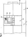
- Fig. 1 and 2 illustrated first example of the lathe while the electronic visualization device 60 is still arranged on the sliding hood 44, but instead of a hitherto customary viewing window, so that by removing the safety-critical viewing window, the sliding hood 44 can be windowless and thus safer.
- the electronic visualization device 60 at another location of the machine casing 40 or on the machine frame 10 directly or by means of a carrier or an arm, for example at a location which is a greater distance from the sliding hood 44, so that the Sliding hood 44 can still be provided with a viewing window, but the observation of the operation must not be done on the viewing window, but can be done in the secure environment in which the electronic visualization device 60 is arranged.
- the first example of the lathe provides for this purpose that in the work space 30 cameras 70, 72 are arranged, which allow the operation in the work space 30 to capture and transmit in the form of electronic image information of a visualization processor unit 80, which from this electronic image information control information for the visualization device 60 generates in order to reproduce thereon an image of the processing units 12, 14, 16 recorded by the cameras 70, 72 ( Fig. 3 ).
- the cameras 70, 72 are video cameras operating in the visible spectral range, the electronic image information of which is processed by the visualization processor unit 80 such that the actions of the first processing units 12 and 14 assigned to them are displayed on the electronic visualization device 60 Tools 24 and 26 and all actions of the second processing unit 16 and held in this workpiece 20 can be displayed.
- either one of the cameras 70, 72 or both cameras 70, 72 are designed as infrared cameras, which thus detect the conditions in the working space 30 in a different spectral range, thereby opening up the possibility, alternatively or additionally
- the machining units 12, 14, 16 with the workpiece 20 and the tools 24 and 26 in the visible spectral range it is therefore possible on the one hand to detect the machining units 12, 14, 16 with the workpiece 20 and the tools 24 and 26 in the visible spectral range and to display them on the electronic visualization device 60, but at the same time also the working units described above 12, 14, 16 with the workpiece 20 and the tools 24 and 26 in the infrared spectral range to capture and recorded in the infrared spectral image information simultaneously and for example even side by side or superimposed to the image information from the visible spectral range on the electronic visualization device 60, so that an operator over known solutions receives improved image information concerning the operations in the working space 30 and thus can better assess the running in the working space 30 operation.
- the visualization processor unit 80 is provided with an input field 82, which allows the desired image information, that is image information in the visible or, for example, infrared spectral range, to select and also to select the type of presentation, namely whether this image information is displayed next to each other or one above the other to be able to optimally observe the operation on the electronic visualization device 60.
- desired image information that is image information in the visible or, for example, infrared spectral range
- the machine controller 48 operates in the first example as a conventional known machine controller which drives with target position values SP a drive means 90, which in turn drive motors or actuators 92, 94, 96, 98 for moving the processing units in each case one of the axes of movement X, Y, Z operates ( Fig. 3 ).
- the visualization processor unit 80 is still provided with a picture information storage unit 84 to store the image information displayed on the electronic visualization device 60 parallel to the display, so that it is possible, for example in a collision case taking place in the workspace 30, to reproduce the collisions leading to the collision and, for example be displayed in slow motion by the image information from the image information storage unit 84 are read out for display on the electronic image capture unit, so that for a definable past period all image information displayed on the electronic visualization device 60 and optionally also on this image information not shown again and thereby the cause of the collision in the working space 30 can be determined retrospectively.
- the visualization processor unit 80 is provided with a simulation processor unit 86, which receives control information from the machine controller 48 to an actual process running in the workspace 30.
- the third embodiment is configured such that the machine controller 48 of the drive device 90 transmits the target position values SP required to drive the drive motors or actuators 92, 94, 96, 98 for moving the processing units 12, 14, 16, and these setpoint position values SP are also simultaneously transmitted to the simulation processor unit 86 transmitted.
- Simulation processing unit 86 now generates virtual processing units 12V, 14V, and 16V with virtual tools 24V and 26V, based on geometric configurations of virtual processing units stored in memory 88 that substantially correspond to real processing units 12, 14, 16 in their geometric shape and dimension and a virtual workpiece 20V and presents them on the electronic visualization device 60.
- All movements of the real working units 12, 14, 16 controlled by the work program 46 of the machine control 48 through the predetermined setpoint position values SP are represented on the electronic visualization device 60 by movements of the virtual processing units 12V, 14V, 16V in that the simulation processor unit 86 on the one hand displays the graphic representations of the virtual processing units 12V, 14V, 16V is read from the memory 88 and displayed on the visualization device 60, and on the other hand, these virtual processing units 12V, 14V, 16V are moved relative to each other according to the target position values SP transmitted to the simulation processor unit 86.
- the desired position values SP are communicated synchronously to both the drive device 90 and the simulation processor unit 86, the representation of the real work process controlled by the machine control 48 and the simulated work process represented by the simulation processor unit 86 based on the desired position values SP on the electronic visualization device 60 is shown the virtual processing units 12V, 14V, 16V substantially in synchronism with each other.
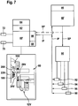
- FIG Fig. 7 In a fourth embodiment of a lathe according to the invention, shown in FIG Fig. 7 are those elements which are identical to those of the preceding embodiments, provided with the same reference numerals, so that with regard to the description of the same can be fully incorporated by reference to the statements to the preceding embodiments.
- the machine control 48 'of the visualization processor unit 80' does not provide target position values SP, but actual position values IP obtained from the individual drive motors or actuators 92, 94, 96, 98 from the machine control 48 'be queried.
- the operator has the ability to accurately track the movements of the virtual processing units 12V, 14V, 16V on the electronic visualization device 60 as the corresponding processing units 12, 14, 16 actually move in the workspace 30.
- the operator also has the option, for example in the case of damage or collisions, using the image information stored in the image information storage unit 84 to retrospectively determine the movements or states after which, for example, a collision situation has occurred, since the simulated work process is exactly the same Machining process with all possibly occurring in the workspace 30 positioning errors or deficiencies corresponds.
- the simulation processor unit 86 can represent both a simulated machining operation based on the actual positions IP and a simulated machining process based on the desired positions SP on the electronic visualization device 60 and thus the operator the opportunity to determine how the deviations between the target positions with sufficiently large computer capacity and the actual positions are, which in particular also in the case of a collision situation or a machine damage allows further information about the occurrence of the same.
- the simulated operation on the basis of the actual positions IP in a full screen on the electronic visualization device 60 while the simulated due to the desired positions SP operation is displayed as semi-transparent image on the electronic display device 60, so that at Superimposing the "full screen” display mode and the "semitransparent" display mode, the operator can immediately recognize the differences between the desired positions SP and actual positions IP.
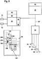
- FIG Fig. 8 In a fifth embodiment, shown in FIG Fig. 8 , those elements that are identical to those of the preceding embodiments are provided with the same reference numerals, so that with regard to the description of the same can be made in full content to the comments on the above embodiments.
- not only actual positions IP of the drive motors or actuators 92, 94, 96, 98 are interrogated by the machine control 48 "in connection with the operation of the lathe, in particular the machining units 12, 14, 16, but additionally actual state values IZ, which are determined by state sensors 102, 104, 106, 108, wherein these state sensors 102, 104, 106, 108 are, for example, temperature sensors which are either directly associated with the drive motors or actuators 92, 94, 96, 98 or, for example, with the drive motors or actuators 92, 94, 96, 98 moving processing units 12, 14, 18 or the corresponding with these processing units 12, 14 moving tools 24, 26, so that the machine control 48 "has the ability to detect, for example, thermal overheating conditions and, where appropriate, appropriate warnings to give.
- these actual state values IZ are also transmitted to the simulation processor unit 86, and the simulation processor unit 86 selects graphic symbols from the memory 88 corresponding to the respective actual state values IZ, which in connection with the respective virtual processing unit 12V, 14V; 16V or the respective virtual tool 24V, 26V or also the workpiece 20V.
- Such symbols may be, for example, warning symbols or colorations of the respective illustrated virtual processing units 12V, 14V; 16V or each of the illustrated virtual tools 24V, 26V or each represented virtual workpiece 20V.
- a green color coding of the corresponding processing unit 12V, 14V, 16V or the respective virtual tool 24V, 26V or the workpiece 20V may mean a permissible temperature, while a yellow or even a red color underlay of the corresponding processing unit 12V, 14V, 16V or the corresponding Tool 24V, 26V or the workpiece 20V indicates heating or overheating.
- the simulation processor unit 86 may also graphically display to an operator by means of graphical elements from the memory 88 if, for example, this force exceeds a permissible level This can also be done by any graphical elements or color underlay the corresponding virtual processing unit 12V, 14V, 16V.
- the machine control 48 is capable of determining actual status values IS of the lathe, for example with status sensors 112, 114, 116, 118 which indicate, for example, whether a turret of a processing unit 12, 14 after a Switching state is properly locked, whether one of the working units 12, 14 or 16 a certain position to be taken is actually reached or whether other conditions that are required for proper operation of the lathe, are present or maintained.
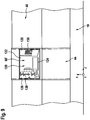
- FIG Fig. 9 the visualization device 60 'is provided with a display area 120 which can be divided into different fields.
- the display area 120 comprises a display screen 122 for displaying a machine image, a display field 124 for displaying function data of the machine control 48 and display fields 126 and 128, on which operating elements 130 are displayed, wherein the display fields 126 and 128 are simultaneously designed as touchscreen fields, that is, upon touching the controls 130 displayed in the display panels 126 and 128, a function operation of either of Visualization processor unit 80 or the machine control 48 is possible.
- the representation of the operating elements 130 and the operating functions assigned to these operating elements 130 in the display fields 126 and 128 can be defined by an operating software, so that both the arrangement of the operating elements 130 and their functions can be defined by the operating software.
- the visualization device 60 not only allows the representation of the processing units 12, 14, 16 or the virtual processing units 12V, 14V, 16V in the display field 122, but also the representation of function data of the machine control in the display panel 124 and also the operation both the visualization processor unit 80 and the machine controller 48 via the controls 130 of the display panels 126 and 128, so that a uniform operation of the entire lathe via the controls 130 of the display panels 126 and 128 is possible.
- the position of the display panels 122, 124, 126, 128 freely selectable That is, if, for example, the display panels 124 and 122 can be arranged differently relative to each other, or if, for example, the display panels 126 and 128 relative to the display panels 122 and 124 can also be arranged on the display panel 120 in a different manner.
Landscapes
- Engineering & Computer Science (AREA)
- Mechanical Engineering (AREA)
- Physics & Mathematics (AREA)
- Optics & Photonics (AREA)
- Human Computer Interaction (AREA)
- Manufacturing & Machinery (AREA)
- General Physics & Mathematics (AREA)
- Automation & Control Theory (AREA)
- Numerical Control (AREA)
- Soil Working Implements (AREA)
- Electrical Discharge Machining, Electrochemical Machining, And Combined Machining (AREA)
- Component Parts Of Construction Machinery (AREA)
Claims (56)
- Tour comportant un bâti de machine (10), au moins une première unité d'usinage (12, 14) disposée sur le bâti de machine (10) dans un espace de travail (30), réalisée comme support d'outil et au moins une seconde unité d'usinage (16) disposée sur le bâti de machine (10) dans l'espace de travail (30), réalisée comme broche de pièce, dont au moins l'une peut être déplacée, commandée par une commande de machine (48), pour la réalisation d'un processus de travail dans l'espace de travail (30), au tour étant associé un dispositif de visualisation électronique (60), sur lequel des processus de travail ayant lieu dans l'espace de travail (30) peuvent être représentés par des illustrations d'unités d'usinage (12, 14, 16) réalisées comme support d'outil et broche de pièce pour un opérateur de manière essentiellement synchrone aux processus de travail réels ayant lieu dans le tour,
caractérisé en ce que le dispositif de visualisation électronique (60) est disposé dans une zone séparée de l'espace de travail (30) par une paroi de protection (50), en ce que le dispositif de visualisation (60) coopère avec une unité de processeur de visualisation (80) qui réalise des simulations de processus de travail et représente un processus de travail réel réalisé par la commande de machine (48) en raison d'un programme de travail réel se déroulant actuellement par des unités d'usinage virtuelles (12V, 14V, 16V) et une simulation de leurs déplacements sur le dispositif de visualisation (60) comme processus de travail virtuel de manière synchrone avec le processus de travail réel effectif se déroulant dans le tour. - Tour selon la revendication 1, caractérisé en ce que le dispositif de visualisation électronique (60) est disposé sur un capot (40) du tour.
- Tour selon la revendication 2, caractérisé en ce que le dispositif de visualisation électronique (60) est disposé près d'une ouverture d'accès (42) à l'espace de travail (30).
- Tour selon l'une quelconque des revendications précédentes, caractérisé en ce que les processus de travail représentés par le dispositif de visualisation (60) peuvent être représentés en décalage dans le temps par rapport aux processus de travail réels ayant lieu dans le tour.
- Tour selon la revendication 4, caractérisé en ce qu'un processus de travail représenté en décalage dans le temps par le dispositif de visualisation (60) est effectué par enregistrement des informations d'image dans une unité d'enregistrement des informations d'image (84) et reproduction suivante de celles-ci.
- Tour selon la revendication 4 ou 5, caractérisé en ce qu'un processus de travail représenté en décalage dans le temps par le dispositif de visualisation (60) peut être représenté par un processus de travail virtuel généré par une simulation préalable d'un réel processus de travail.
- Tour selon l'une quelconque des revendications précédentes, caractérisé en ce que dans l'espace de travail (30) est prévu un dispositif d'acquisition d'image électronique (70, 72) et en ce que les informations d'image acquises par le dispositif d'acquisition d'image (70, 72) peuvent être représentées sur le dispositif de visualisation électronique (60).
- Tour selon la revendication 7, caractérisé en ce que le dispositif d'acquisition d'image électronique (70, 72) travaille dans le domaine spectral visible.
- Tour selon la revendication 7 ou 8, caractérisé en ce que le dispositif d'acquisition d'image électronique (70, 72) travaille dans le domaine spectral infrarouge.
- Tour selon l'une quelconque des revendications 7 à 9, caractérisé en ce que le dispositif d'acquisition d'image (70, 72) présente au moins une puce d'acquisition d'image électronique.
- Tour selon l'une quelconque des revendications précédentes, caractérisé en ce que l'unité de processeur de visualisation (80) simule des mouvements relatifs des unités d'usinage (12, 14, 16).
- Tour selon la revendication 11, caractérisé en ce que l'unité de processeur de visualisation (80) représente des mouvements d'unités d'usinage virtuelles (12V, 14V, 16V) du tour sur le dispositif de visualisation (60).
- Tour selon la revendication 12, caractérisé en ce que l'unité de processeur de visualisation (80) détermine des unités d'usinage virtuelles (12V, 14V, 16V) correspondant aux formes géométriques des unités d'usinage réelles (12, 14, 16) et les représente sur le dispositif de visualisation (60).
- Tour selon l'une quelconque des revendications 10 à 12, caractérisé en ce que l'unité de processeur de visualisation (80) consulte un programme de travail de processus de travail réels pour leur simulation et la représentation d'un processus de travail virtuel avec des unités d'usinage virtuelles (12V, 14V, 16V).
- Tour selon l'une quelconque des revendications précédentes, caractérisé en ce que la commande de machine (48) transmet les grandeurs (SP, IP) déterminées pour les unités d'usinage réelles (12, 14, 16) du tour parallèlement à leur détermination à l'unité de processeur de visualisation (80).
- Tour selon la revendication 15, caractérisé en ce que la commande de machine (48) transmet des valeurs de position (SP, IP) des unités d'usinage réelles (12, 14, 16) à l'unité de processeur de visualisation (80).
- Tour selon la revendication 16, caractérisé en ce que l'unité de processeur de visualisation (80) représente les unités d'usinage virtuelles (12V, 14V, 16V) les unes par rapport aux autres selon les valeurs de position (SP, IP) des unités d'usinage réelles (12, 14, 16).
- Tour selon la revendication 16 ou 17, caractérisé en ce que les valeurs de position sont des valeurs de position de consigne (SP) des unités d'usinage réelles (12, 14, 16).
- Tour selon l'une quelconque des revendications 16 ou 18, caractérisé en ce que la commande de machine (48) transmet des valeurs réelles acquises (IP, IZ, IS) des unités d'usinage réelles (12, 14, 16) à l'unité de processeur de visualisation (80) à des fins de représentation.
- Tour selon la revendication 19, caractérisé en ce que les valeurs réelles sont des valeurs de position réelles (IP) d'au moins l'une des unités d'usinage (12, 14, 16).
- Tour selon la revendication 20, caractérisé en ce que les valeurs de position réelles (IP) représentent au moins une position au moins de l'une des unités d'usinage (12, 14, 16) le long d'au moins l'un des axes de déplacement respectifs (X, Y, Z).
- Tour selon l'une quelconque des revendications 19 à 21, caractérisé en ce que les valeurs réelles sont des valeurs d'état réelles (IZ) pour au moins l'une des grandeurs telles que la force sur une unité d'usinage, la température d'une unité d'usinage, la force sur un outil et la température d'un outil.
- Tour selon l'une quelconque des revendications 19 à 22, caractérisé en ce que les valeurs réelles sont des valeurs de statut réelles (IS) d'éléments de machine.
- Tour selon la revendication 23, caractérisé en ce que les valeurs de statut réelles (IS) sont au moins une information de statut provenant des informations de statut telles que "cylindre devant", "position finale atteinte", "pièce serrée", "outil serré".
- Tour selon l'une quelconque des revendications 19 à 24, caractérisé en ce que l'unité de processeur de visualisation (86) représente graphiquement les valeurs réelles (IP, IZ, IS).
- Tour selon la revendication 25, caractérisé en ce que l'unité de processeur de visualisation (80) représente les valeurs réelles (IP, IZ, IS) par des éléments graphiques enregistrés dans une mémoire (88).
- Tour selon la revendication 26, caractérisé en ce que les éléments graphiques enregistrés sont des configurations géométriques d'unités d'usinage virtuelles (12V, 14V, 16V).
- Tour selon l'une quelconque des revendications 25 à 27, caractérisé en ce que l'unité de processeur de visualisation (80) représente graphiquement les unités d'usinage virtuelles (12V, 14V, 16V) selon des valeurs de position réelles (IP) des unités d'usinage réelles correspondantes (12, 14, 16).
- Tour selon l'une quelconque des revendications 26 à 28, caractérisé en ce que les éléments graphiques enregistrés comportent des symboles d'état pour des informations d'état telles que les forces ou les températures.
- Tour selon la revendication 29, caractérisé en ce que les symboles d'état comportent des coloriages d'unités d'usinage virtuelles (12V, 14V, 16V).
- Tour selon la revendication 29 ou 30, caractérisé en ce que les symboles d'état comportent des symboles d'avertissement graphiques pour au moins l'une des grandeurs telles que la force ou la température.
- Tour selon l'une quelconque des revendications précédentes, caractérisé en ce qu'un processus de travail peut être représenté dans plusieurs modes de représentation avec l'unité de processeur de visualisation (80).
- Tour selon l'une quelconque des revendications précédentes, caractérisé en ce qu'un mode de représentation est la représentation du processus de travail acquis par le dispositif d'acquisition d'image (70, 72).
- Tour selon la revendication 32 ou 33, caractérisé en ce qu'un mode de représentation est la représentation d'un processus de travail simulé.
- Tour selon l'une quelconque des revendications précédentes, caractérisé en ce que les différents modes de représentation peuvent être représentés en même temps sur le dispositif de visualisation (60).
- Tour selon l'une quelconque des revendications 32 à 35, caractérisé en ce que les différents modes de réalisation peuvent être représentés par des représentations se trouvant les unes au-dessus des autres.
- Tour selon l'une quelconque des revendications précédentes, caractérisé en ce que différents modes de représentation peuvent être représentés en même temps sur le dispositif de visualisation (60) par différents types de représentation représentés les uns au-dessus des autres.
- Tour selon l'une quelconque des revendications 32 à 37, caractérisé en ce qu'un type de représentation est une représentation partiellement transparente.
- Tour selon l'une quelconque des revendications 32 à 38, caractérisé en ce qu'un type de représentation est une représentation par des lignes de contour.
- Tour selon l'une quelconque des revendications 32 à 39, caractérisé en ce qu'un type de représentation est une représentation par une image pleine page.
- Tour selon l'une quelconque des revendications précédentes, caractérisé en ce qu'au dispositif de visualisation (60) est associé un pupitre de commande (126, 128).
- Tour selon la revendication 41, caractérisé en ce qu'une sélection du mode de représentation et/ou du type de représentation peut être réalisée avec le pupitre de commande (126, 128).
- Tour selon la revendication 41 ou 42, caractérisé en ce que le pupitre de commande (126, 128) est intégré dans le dispositif de visualisation (60').
- Tour selon la revendication 43, caractérisé en ce que le pupitre de commande (126, 128) est intégré comme un écran tactile dans le dispositif de visualisation (60').
- Tour selon la revendication 44, caractérisé en ce que les fonctions des zones de l'écran tactile (126, 128) peuvent être définies par le logiciel de commande.
- Tour selon la revendication 44 ou 45, caractérisé en ce que les fonctions des éléments de commande individuels (130) du pupitre de commande (126, 128) peuvent être définies par le logiciel de commande.
- Tour selon l'une quelconque des revendications 41 à 46, caractérisé en ce que les fonctions des éléments de commande (130) du pupitre de commande (126, 128) peuvent être définies pour des droitiers.
- Tour selon l'une quelconque des revendications 41 à 46, caractérisé en ce que les fonctions des éléments de commande du pupitre de commande peuvent être définies pour des gauchers.
- Tour selon l'une quelconque des revendications précédentes, caractérisé en ce que le dispositif de visualisation (60') affiche des données fonctionnelles de la commande de machine (48).
- Tour selon la revendication 49, caractérisé en ce que le dispositif de visualisation (60') présente un champ d'affichage (124) pour des informations de la commande de machine (48).
- Tour selon la revendication 49 ou 50, caractérisé en ce que le dispositif de visualisation (60') peut être commuté entre un affichage de données fonctionnelles de la commande de machine et une représentation au moins d'un processus de travail virtuel ou réel.
- Tour selon l'une quelconque des revendications 49 à 51, caractérisé en ce qu'un champ d'affichage (124) pour l'affichage de données fonctionnelles de la commande de machine (48) peut être positionné de manière sélective sur une surface d'affichage (120) du dispositif de visualisation (60').
- Tour selon l'une quelconque des revendications 49 à 52, caractérisé en ce qu'un champ d'affichage pour une image de machine peut être positionné de manière sélective sur la surface d'affichage du dispositif de visualisation (60').
- Tour selon l'une quelconque des revendications précédentes, caractérisé en ce que le dispositif de visualisation (60) est disposé sur une porte (44) fermant l'ouverture d'accès (42) du capot de la machine (40).
- Tour selon la revendication 54, caractérisé en ce que le dispositif de visualisation (60) est prévu à la place d'une fenêtre d'inspection sur la porte (44).
- Tour selon la revendication 54 ou 55, caractérisé en ce que le pupitre de commande (126, 128) est prévu sur la porte (44).
Applications Claiming Priority (1)
| Application Number | Priority Date | Filing Date | Title |
|---|---|---|---|
| DE102006059819A DE102006059819A1 (de) | 2006-12-11 | 2006-12-11 | Arbeitsmaschine |
Publications (3)
| Publication Number | Publication Date |
|---|---|
| EP1932618A1 EP1932618A1 (fr) | 2008-06-18 |
| EP1932618B1 EP1932618B1 (fr) | 2010-11-03 |
| EP1932618B2 true EP1932618B2 (fr) | 2017-02-22 |
Family
ID=39073704
Family Applications (1)
| Application Number | Title | Priority Date | Filing Date |
|---|---|---|---|
| EP07023792.0A Active EP1932618B2 (fr) | 2006-12-11 | 2007-12-07 | Machine de travail |
Country Status (3)
| Country | Link |
|---|---|
| EP (1) | EP1932618B2 (fr) |
| AT (1) | ATE486690T1 (fr) |
| DE (2) | DE102006059819A1 (fr) |
Cited By (1)
| Publication number | Priority date | Publication date | Assignee | Title |
|---|---|---|---|---|
| US10759016B2 (en) * | 2016-03-10 | 2020-09-01 | Dmg Mori Co., Ltd. | Machine tool provided with camera for capturing image of tool interior |
Families Citing this family (24)
| Publication number | Priority date | Publication date | Assignee | Title |
|---|---|---|---|---|
| DE102009045298A1 (de) * | 2009-10-02 | 2011-04-07 | Traub Drehmaschinen Gmbh & Co. Kg | Optisches Assistenzsystem für Werkzeugmaschinen |
| DE102010011475B4 (de) * | 2010-03-16 | 2015-10-29 | Jens Mehnert | Maschinentür und Verfahren zum Betrieb |
| DE102010046274A1 (de) * | 2010-09-22 | 2012-03-22 | Netstal-Maschinen Ag | Verfahren zur Überprüfung eines hinterlegten Produktionsablaufes für eine oder mehrere Maschinen mit einem zyklischen Maschinenbetriebsablauf |
| DE102010053485B4 (de) * | 2010-12-04 | 2026-01-15 | Robert Bosch Gmbh | Verfahren und Arbeitsmaschine mit virtueller Maschinenverwaltung |
| DE102013208355A1 (de) * | 2013-05-07 | 2014-11-13 | Krones Ag | Vorrichtung und Verfahren zur Aufbringung einer Etikettenhülse |
| CN103862356B (zh) * | 2014-03-10 | 2017-02-22 | 浙江埃弗逊机电科技有限公司 | 一种珩磨机 |
| EP3082001B1 (fr) * | 2015-04-13 | 2020-09-09 | Siemens Aktiengesellschaft | Procédé d'extension d'un dispositif d'automatisation avec un virtuel appareil d'automatisation et dispositif d'automatisation |
| DE102015215625A1 (de) * | 2015-08-17 | 2017-02-23 | Schaeffler Technologies AG & Co. KG | Montage- und/oder Bearbeitungsmaschine, damit gebildete Fertigungsstraße sowie Fertigungsanlage |
| EP3144751B1 (fr) | 2015-09-18 | 2021-10-27 | Siemens Aktiengesellschaft | Système de commande et procédé de fonctionnement d'un système de commande doté d'une commande réelle et virtuelle destinée à la surveillance de processus |
| EP3144758A1 (fr) | 2015-09-18 | 2017-03-22 | Siemens Aktiengesellschaft | Systeme de commande et procede de fonctionnement d'un systeme de commande dote d'une commande reelle et virtuelle |
| EP3144756A1 (fr) | 2015-09-18 | 2017-03-22 | Siemens Aktiengesellschaft | Systeme de commande et procede de fonctionnement d'un systeme de commande dote d'une commande reelle et virtuelle destine a reduire les temps d'arret |
| DE102015119806A1 (de) * | 2015-11-16 | 2017-05-18 | Grob-Werke Gmbh & Co. Kg | Verfahren zur Darstellung der Bearbeitung in einer Werkzeugmaschine |
| JP6526596B2 (ja) * | 2016-04-15 | 2019-06-05 | 高松機械工業株式会社 | 工作機械 |
| EP3511120B1 (fr) * | 2016-09-09 | 2022-11-30 | Makino J Co., Ltd. | Machine-outil pourvue d'un dispositif d'affichage |
| JP2018094689A (ja) | 2016-12-15 | 2018-06-21 | 中村留精密工業株式会社 | 工作機械 |
| CN108247428A (zh) * | 2016-12-29 | 2018-07-06 | 中村留精密工业株式会社 | 工作机械 |
| EP3348350B1 (fr) * | 2017-01-16 | 2020-05-06 | Nakamura-Tome Precision Industry Co., Ltd | Machine-outil avec caméra |
| EP3454149A1 (fr) * | 2017-09-11 | 2019-03-13 | Siemens Aktiengesellschaft | Attribution optimisée des signaux de processus permettant la détermination des contours d'une pièce à usiner |
| CN109015112A (zh) * | 2018-10-17 | 2018-12-18 | 苏州市斯可源自动化科技有限公司 | 一种机床防护门 |
| AT522653B1 (de) * | 2019-05-15 | 2025-12-15 | Wittmann Tech Gmbh | Verfahren zur Darstellung und Bedienung von Produktionsmitteln, insbesondere für die kunststoffverarbeitende Industrie |
| IT202000003230A1 (it) * | 2020-02-18 | 2021-08-18 | Scm Group Spa | Macchina utensile per la lavorazione di pezzi configurata per controllare una o piu’ fasi di lavorazione |
| DE102020123394B4 (de) | 2020-09-08 | 2022-12-01 | Hema Maschinen- Und Apparateschutz Gmbh | Einsatz für eine Abdeckung einer Werkzeugmaschine |
| JP7808540B2 (ja) * | 2022-11-04 | 2026-01-29 | Dmg森精機株式会社 | 工作機械 |
| JP7678600B2 (ja) * | 2023-07-07 | 2025-05-16 | 株式会社リンスコネクト | 工作機械 |
Citations (3)
| Publication number | Priority date | Publication date | Assignee | Title |
|---|---|---|---|---|
| EP0346839B1 (fr) † | 1988-06-13 | 1995-09-13 | Nissan Motor Co., Ltd. | Méthode et système pour l'apprentissage des robots |
| EP1480095A1 (fr) † | 1997-09-09 | 2004-11-24 | Traub Drehmaschinen GmbH | Procédé et système d'établissement ou de visualisation des ensembles de données de contrôle |
| DE102004048037A1 (de) † | 2004-09-29 | 2006-04-06 | Index-Werke Gmbh & Co. Kg Hahn & Tessky | Werkzeugmaschine |
Family Cites Families (9)
| Publication number | Priority date | Publication date | Assignee | Title |
|---|---|---|---|---|
| GB9618109D0 (en) * | 1996-08-30 | 1996-10-09 | Middlesex Group Ltd | Load monitoring apparatus |
| WO1999013386A1 (fr) * | 1997-09-09 | 1999-03-18 | Schäublin S.A. | Procede de generation d'un plan d'usinage de piece pour commande numerique de machine-outil |
| DE19824219B4 (de) * | 1998-05-29 | 2007-11-22 | Max Mayer Maschinenbau Gmbh | Verfahren und System zur Einrichtung von CNC-Maschinen |
| JP4605875B2 (ja) * | 2000-09-04 | 2011-01-05 | 本田技研工業株式会社 | 加工具欠損検出装置 |
| DE10044306A1 (de) * | 2000-09-07 | 2002-04-04 | Juergen Roeders | Werkzeugmaschine |
| JP2002123306A (ja) * | 2000-10-17 | 2002-04-26 | Toshiba Mach Co Ltd | 工作機械の監視システム |
| JP2004227411A (ja) * | 2003-01-24 | 2004-08-12 | Toyota Motor Corp | 数値制御加工制御システム |
| JP2006085328A (ja) * | 2004-09-15 | 2006-03-30 | Toyoda Mach Works Ltd | 工作機械制御装置 |
| DE102005038718B3 (de) * | 2005-08-15 | 2006-08-31 | Uhlmann Pac-Systeme Gmbh & Co. Kg | Verpackungsmaschine |
-
2006
- 2006-12-11 DE DE102006059819A patent/DE102006059819A1/de not_active Ceased
-
2007
- 2007-12-07 AT AT07023792T patent/ATE486690T1/de active
- 2007-12-07 EP EP07023792.0A patent/EP1932618B2/fr active Active
- 2007-12-07 DE DE502007005541T patent/DE502007005541D1/de active Active
Patent Citations (3)
| Publication number | Priority date | Publication date | Assignee | Title |
|---|---|---|---|---|
| EP0346839B1 (fr) † | 1988-06-13 | 1995-09-13 | Nissan Motor Co., Ltd. | Méthode et système pour l'apprentissage des robots |
| EP1480095A1 (fr) † | 1997-09-09 | 2004-11-24 | Traub Drehmaschinen GmbH | Procédé et système d'établissement ou de visualisation des ensembles de données de contrôle |
| DE102004048037A1 (de) † | 2004-09-29 | 2006-04-06 | Index-Werke Gmbh & Co. Kg Hahn & Tessky | Werkzeugmaschine |
Cited By (1)
| Publication number | Priority date | Publication date | Assignee | Title |
|---|---|---|---|---|
| US10759016B2 (en) * | 2016-03-10 | 2020-09-01 | Dmg Mori Co., Ltd. | Machine tool provided with camera for capturing image of tool interior |
Also Published As
| Publication number | Publication date |
|---|---|
| ATE486690T1 (de) | 2010-11-15 |
| EP1932618B1 (fr) | 2010-11-03 |
| EP1932618A1 (fr) | 2008-06-18 |
| DE502007005541D1 (de) | 2010-12-16 |
| DE102006059819A1 (de) | 2008-06-19 |
Similar Documents
| Publication | Publication Date | Title |
|---|---|---|
| EP1932618B2 (fr) | Machine de travail | |
| DE102018109463C5 (de) | Verfahren zur Benutzung einer mehrgliedrigen aktuierten Kinematik, vorzugsweise eines Roboters, besonders vorzugsweise eines Knickarmroboters, durch einen Benutzer mittels einer mobilen Anzeigevorrichtung | |
| EP2639012B1 (fr) | Procédé de fonctionnement d'une machine de traitement, dispositif de projection pour une machine de traitement, programme informatique, support de stockage digital et machine de traitement dotée d'un tel dispositif de projection | |
| EP1484133B1 (fr) | Machine de production ou machine-outil avec une vitre transparente et système d'affichage tête-haute | |
| DE102017124502B4 (de) | Simulationsvorrichung und Simulationsverfahren, die eine Betriebssimulation eines Robotersystems ausführen, und Aufzeichnungsmedium, das ein Computerprogramm aufzeichnet | |
| DE10325894B4 (de) | Werkzeug- oder Produktionsmaschine mit Anzeigeeinheit zur Visualisierung von Arbeitsabläufen | |
| DE102013114372A1 (de) | Laststand-anzeige für eine werkzeugmaschine | |
| DE102014221705A1 (de) | Werkzeugmaschine | |
| DE102010039540B4 (de) | Handbediengerät zum manuellen Bewegen eines Roboterarms | |
| EP2465639B9 (fr) | Machine-outil | |
| DE102010036499A1 (de) | Werkzeugvektor-Anzeigevorrichtung für eine Werkzeugmaschine mit Drehachse | |
| EP1906281B1 (fr) | Procédé et système pour la conception et la vérification de zones de sécurité d'un robot industriel | |
| WO2009037065A1 (fr) | Procédé et machine-outil virtuelle servant à représenter des actions d'une machine-outil réelle | |
| DE102005045028A1 (de) | Simulationssystem | |
| DE202014010054U1 (de) | Protektofon - eine kognitive Sicherheitsfunktion | |
| DE102014219831A1 (de) | Anzeigevorrichtung | |
| DE102013015024A1 (de) | Verzahnmaschine | |
| DE102018123124B4 (de) | Werkzeugmaschine und Steuerverfahren für Werkzeugmaschine | |
| EP3234442B1 (fr) | Procédé de surveillance d'un appareil de mesure de coordonnées | |
| EP2216697A1 (fr) | Machine outil et procédé pour éviter une collision dans une machine outil | |
| EP3168701B1 (fr) | Procédé de représentation de l'usinage dans une machine-outil | |
| EP2310167B1 (fr) | Procédé de commande du manipulateur de pièce d'une machine-outil après une interruption du processus d'usinage | |
| DE102018113361B4 (de) | Sensorsystem mit optoelektronischen Distanzsensoren | |
| DE102014000789A1 (de) | Werkzeugmaschine mit Displayvorrichtung | |
| EP2625008A1 (fr) | Commande de robot |
Legal Events
| Date | Code | Title | Description |
|---|---|---|---|
| PUAI | Public reference made under article 153(3) epc to a published international application that has entered the european phase |
Free format text: ORIGINAL CODE: 0009012 |
|
| AK | Designated contracting states |
Kind code of ref document: A1 Designated state(s): AT BE BG CH CY CZ DE DK EE ES FI FR GB GR HU IE IS IT LI LT LU LV MC MT NL PL PT RO SE SI SK TR |
|
| AX | Request for extension of the european patent |
Extension state: AL BA HR MK RS |
|
| RIN1 | Information on inventor provided before grant (corrected) |
Inventor name: DUDIC, IVAN DR. -ING. Inventor name: BECK, EBERHARD DIPL. -ING. Inventor name: SEEGER, HARTMUT PROF. DIPL.-ING. Inventor name: MAIER, THOMAS PROF. DR. -ING. |
|
| 17P | Request for examination filed |
Effective date: 20081205 |
|
| 17Q | First examination report despatched |
Effective date: 20090112 |
|
| AKX | Designation fees paid |
Designated state(s): AT BE BG CH CY CZ DE DK EE ES FI FR GB GR HU IE IS IT LI LT LU LV MC MT NL PL PT RO SE SI SK TR |
|
| GRAP | Despatch of communication of intention to grant a patent |
Free format text: ORIGINAL CODE: EPIDOSNIGR1 |
|
| GRAS | Grant fee paid |
Free format text: ORIGINAL CODE: EPIDOSNIGR3 |
|
| GRAA | (expected) grant |
Free format text: ORIGINAL CODE: 0009210 |
|
| AK | Designated contracting states |
Kind code of ref document: B1 Designated state(s): AT BE BG CH CY CZ DE DK EE ES FI FR GB GR HU IE IS IT LI LT LU LV MC MT NL PL PT RO SE SI SK TR |
|
| REG | Reference to a national code |
Ref country code: GB Ref legal event code: FG4D Free format text: NOT ENGLISH |
|
| REG | Reference to a national code |
Ref country code: CH Ref legal event code: EP |
|
| REG | Reference to a national code |
Ref country code: IE Ref legal event code: FG4D Free format text: LANGUAGE OF EP DOCUMENT: GERMAN |
|
| REG | Reference to a national code |
Ref country code: CH Ref legal event code: NV Representative=s name: KIRKER & CIE S.A. |
|
| REF | Corresponds to: |
Ref document number: 502007005541 Country of ref document: DE Date of ref document: 20101216 Kind code of ref document: P |
|
| REG | Reference to a national code |
Ref country code: SE Ref legal event code: TRGR |
|
| REG | Reference to a national code |
Ref country code: NL Ref legal event code: VDEP Effective date: 20101103 |
|
| LTIE | Lt: invalidation of european patent or patent extension |
Effective date: 20101103 |
|
| PG25 | Lapsed in a contracting state [announced via postgrant information from national office to epo] |
Ref country code: LT Free format text: LAPSE BECAUSE OF FAILURE TO SUBMIT A TRANSLATION OF THE DESCRIPTION OR TO PAY THE FEE WITHIN THE PRESCRIBED TIME-LIMIT Effective date: 20101103 |
|
| REG | Reference to a national code |
Ref country code: IE Ref legal event code: FD4D |
|
| PG25 | Lapsed in a contracting state [announced via postgrant information from national office to epo] |
Ref country code: SI Free format text: LAPSE BECAUSE OF FAILURE TO SUBMIT A TRANSLATION OF THE DESCRIPTION OR TO PAY THE FEE WITHIN THE PRESCRIBED TIME-LIMIT Effective date: 20101103 Ref country code: BG Free format text: LAPSE BECAUSE OF FAILURE TO SUBMIT A TRANSLATION OF THE DESCRIPTION OR TO PAY THE FEE WITHIN THE PRESCRIBED TIME-LIMIT Effective date: 20110203 Ref country code: NL Free format text: LAPSE BECAUSE OF FAILURE TO SUBMIT A TRANSLATION OF THE DESCRIPTION OR TO PAY THE FEE WITHIN THE PRESCRIBED TIME-LIMIT Effective date: 20101103 Ref country code: IS Free format text: LAPSE BECAUSE OF FAILURE TO SUBMIT A TRANSLATION OF THE DESCRIPTION OR TO PAY THE FEE WITHIN THE PRESCRIBED TIME-LIMIT Effective date: 20110303 Ref country code: PT Free format text: LAPSE BECAUSE OF FAILURE TO SUBMIT A TRANSLATION OF THE DESCRIPTION OR TO PAY THE FEE WITHIN THE PRESCRIBED TIME-LIMIT Effective date: 20110303 Ref country code: FI Free format text: LAPSE BECAUSE OF FAILURE TO SUBMIT A TRANSLATION OF THE DESCRIPTION OR TO PAY THE FEE WITHIN THE PRESCRIBED TIME-LIMIT Effective date: 20101103 Ref country code: LV Free format text: LAPSE BECAUSE OF FAILURE TO SUBMIT A TRANSLATION OF THE DESCRIPTION OR TO PAY THE FEE WITHIN THE PRESCRIBED TIME-LIMIT Effective date: 20101103 |
|
| BERE | Be: lapsed |
Owner name: INDEX-WERKE G.M.B.H. & CO. KG HAHN & TESSKY Effective date: 20101231 |
|
| PG25 | Lapsed in a contracting state [announced via postgrant information from national office to epo] |
Ref country code: GR Free format text: LAPSE BECAUSE OF FAILURE TO SUBMIT A TRANSLATION OF THE DESCRIPTION OR TO PAY THE FEE WITHIN THE PRESCRIBED TIME-LIMIT Effective date: 20110204 |
|
| PG25 | Lapsed in a contracting state [announced via postgrant information from national office to epo] |
Ref country code: ES Free format text: LAPSE BECAUSE OF FAILURE TO SUBMIT A TRANSLATION OF THE DESCRIPTION OR TO PAY THE FEE WITHIN THE PRESCRIBED TIME-LIMIT Effective date: 20110214 Ref country code: IE Free format text: LAPSE BECAUSE OF FAILURE TO SUBMIT A TRANSLATION OF THE DESCRIPTION OR TO PAY THE FEE WITHIN THE PRESCRIBED TIME-LIMIT Effective date: 20101103 Ref country code: EE Free format text: LAPSE BECAUSE OF FAILURE TO SUBMIT A TRANSLATION OF THE DESCRIPTION OR TO PAY THE FEE WITHIN THE PRESCRIBED TIME-LIMIT Effective date: 20101103 Ref country code: CZ Free format text: LAPSE BECAUSE OF FAILURE TO SUBMIT A TRANSLATION OF THE DESCRIPTION OR TO PAY THE FEE WITHIN THE PRESCRIBED TIME-LIMIT Effective date: 20101103 Ref country code: MC Free format text: LAPSE BECAUSE OF NON-PAYMENT OF DUE FEES Effective date: 20101231 |
|
| PLBI | Opposition filed |
Free format text: ORIGINAL CODE: 0009260 |
|
| PG25 | Lapsed in a contracting state [announced via postgrant information from national office to epo] |
Ref country code: RO Free format text: LAPSE BECAUSE OF FAILURE TO SUBMIT A TRANSLATION OF THE DESCRIPTION OR TO PAY THE FEE WITHIN THE PRESCRIBED TIME-LIMIT Effective date: 20101103 Ref country code: DK Free format text: LAPSE BECAUSE OF FAILURE TO SUBMIT A TRANSLATION OF THE DESCRIPTION OR TO PAY THE FEE WITHIN THE PRESCRIBED TIME-LIMIT Effective date: 20101103 Ref country code: SK Free format text: LAPSE BECAUSE OF FAILURE TO SUBMIT A TRANSLATION OF THE DESCRIPTION OR TO PAY THE FEE WITHIN THE PRESCRIBED TIME-LIMIT Effective date: 20101103 Ref country code: PL Free format text: LAPSE BECAUSE OF FAILURE TO SUBMIT A TRANSLATION OF THE DESCRIPTION OR TO PAY THE FEE WITHIN THE PRESCRIBED TIME-LIMIT Effective date: 20101103 |
|
| PLAX | Notice of opposition and request to file observation + time limit sent |
Free format text: ORIGINAL CODE: EPIDOSNOBS2 |
|
| PG25 | Lapsed in a contracting state [announced via postgrant information from national office to epo] |
Ref country code: BE Free format text: LAPSE BECAUSE OF NON-PAYMENT OF DUE FEES Effective date: 20101231 |
|
| REG | Reference to a national code |
Ref country code: DE Ref legal event code: R026 Ref document number: 502007005541 Country of ref document: DE Effective date: 20110727 |
|
| PG25 | Lapsed in a contracting state [announced via postgrant information from national office to epo] |
Ref country code: MT Free format text: LAPSE BECAUSE OF FAILURE TO SUBMIT A TRANSLATION OF THE DESCRIPTION OR TO PAY THE FEE WITHIN THE PRESCRIBED TIME-LIMIT Effective date: 20101103 Ref country code: IT Free format text: LAPSE BECAUSE OF NON-PAYMENT OF DUE FEES Effective date: 20101207 |
|
| PLAF | Information modified related to communication of a notice of opposition and request to file observations + time limit |
Free format text: ORIGINAL CODE: EPIDOSCOBS2 |
|
| PLAF | Information modified related to communication of a notice of opposition and request to file observations + time limit |
Free format text: ORIGINAL CODE: EPIDOSCOBS2 |
|
| PLAB | Opposition data, opponent's data or that of the opponent's representative modified |
Free format text: ORIGINAL CODE: 0009299OPPO |
|
| R26 | Opposition filed (corrected) |
Opponent name: SIEMENS AG Effective date: 20110727 |
|
| PLAF | Information modified related to communication of a notice of opposition and request to file observations + time limit |
Free format text: ORIGINAL CODE: EPIDOSCOBS2 |
|
| PLBB | Reply of patent proprietor to notice(s) of opposition received |
Free format text: ORIGINAL CODE: EPIDOSNOBS3 |
|
| GBPC | Gb: european patent ceased through non-payment of renewal fee |
Effective date: 20111207 |
|
| PG25 | Lapsed in a contracting state [announced via postgrant information from national office to epo] |
Ref country code: CY Free format text: LAPSE BECAUSE OF FAILURE TO SUBMIT A TRANSLATION OF THE DESCRIPTION OR TO PAY THE FEE WITHIN THE PRESCRIBED TIME-LIMIT Effective date: 20101103 |
|
| PLAB | Opposition data, opponent's data or that of the opponent's representative modified |
Free format text: ORIGINAL CODE: 0009299OPPO |
|
| PG25 | Lapsed in a contracting state [announced via postgrant information from national office to epo] |
Ref country code: LU Free format text: LAPSE BECAUSE OF NON-PAYMENT OF DUE FEES Effective date: 20101207 Ref country code: HU Free format text: LAPSE BECAUSE OF FAILURE TO SUBMIT A TRANSLATION OF THE DESCRIPTION OR TO PAY THE FEE WITHIN THE PRESCRIBED TIME-LIMIT Effective date: 20110504 |
|
| R26 | Opposition filed (corrected) |
Opponent name: SIEMENS AG Effective date: 20110727 |
|
| PG25 | Lapsed in a contracting state [announced via postgrant information from national office to epo] |
Ref country code: TR Free format text: LAPSE BECAUSE OF FAILURE TO SUBMIT A TRANSLATION OF THE DESCRIPTION OR TO PAY THE FEE WITHIN THE PRESCRIBED TIME-LIMIT Effective date: 20101103 Ref country code: GB Free format text: LAPSE BECAUSE OF NON-PAYMENT OF DUE FEES Effective date: 20111207 |
|
| APBM | Appeal reference recorded |
Free format text: ORIGINAL CODE: EPIDOSNREFNO |
|
| APBP | Date of receipt of notice of appeal recorded |
Free format text: ORIGINAL CODE: EPIDOSNNOA2O |
|
| APAH | Appeal reference modified |
Free format text: ORIGINAL CODE: EPIDOSCREFNO |
|
| APAW | Appeal reference deleted |
Free format text: ORIGINAL CODE: EPIDOSDREFNO |
|
| APBQ | Date of receipt of statement of grounds of appeal recorded |
Free format text: ORIGINAL CODE: EPIDOSNNOA3O |
|
| APBQ | Date of receipt of statement of grounds of appeal recorded |
Free format text: ORIGINAL CODE: EPIDOSNNOA3O |
|
| REG | Reference to a national code |
Ref country code: AT Ref legal event code: MM01 Ref document number: 486690 Country of ref document: AT Kind code of ref document: T Effective date: 20121207 |
|
| PG25 | Lapsed in a contracting state [announced via postgrant information from national office to epo] |
Ref country code: AT Free format text: LAPSE BECAUSE OF NON-PAYMENT OF DUE FEES Effective date: 20121207 |
|
| PLAB | Opposition data, opponent's data or that of the opponent's representative modified |
Free format text: ORIGINAL CODE: 0009299OPPO |
|
| R26 | Opposition filed (corrected) |
Opponent name: SIEMENS AKTIENGESELLSCHAFT Effective date: 20110727 |
|
| APAH | Appeal reference modified |
Free format text: ORIGINAL CODE: EPIDOSCREFNO |
|
| PLAB | Opposition data, opponent's data or that of the opponent's representative modified |
Free format text: ORIGINAL CODE: 0009299OPPO |
|
| APAH | Appeal reference modified |
Free format text: ORIGINAL CODE: EPIDOSCREFNO |
|
| R26 | Opposition filed (corrected) |
Opponent name: SIEMENS AKTIENGESELLSCHAFT Effective date: 20110727 |
|
| REG | Reference to a national code |
Ref country code: DE Ref legal event code: R082 Ref document number: 502007005541 Country of ref document: DE Representative=s name: HOEGER, STELLRECHT & PARTNER PATENTANWAELTE MB, DE |
|
| REG | Reference to a national code |
Ref country code: FR Ref legal event code: PLFP Year of fee payment: 9 |
|
| APBU | Appeal procedure closed |
Free format text: ORIGINAL CODE: EPIDOSNNOA9O |
|
| REG | Reference to a national code |
Ref country code: FR Ref legal event code: PLFP Year of fee payment: 10 |
|
| PUAH | Patent maintained in amended form |
Free format text: ORIGINAL CODE: 0009272 |
|
| STAA | Information on the status of an ep patent application or granted ep patent |
Free format text: STATUS: PATENT MAINTAINED AS AMENDED |
|
| 27A | Patent maintained in amended form |
Effective date: 20170222 |
|
| AK | Designated contracting states |
Kind code of ref document: B2 Designated state(s): AT BE BG CH CY CZ DE DK EE ES FI FR GB GR HU IE IS IT LI LT LU LV MC MT NL PL PT RO SE SI SK TR |
|
| REG | Reference to a national code |
Ref country code: DE Ref legal event code: R102 Ref document number: 502007005541 Country of ref document: DE |
|
| REG | Reference to a national code |
Ref country code: CH Ref legal event code: AELC |
|
| REG | Reference to a national code |
Ref country code: SE Ref legal event code: RPEO |
|
| REG | Reference to a national code |
Ref country code: FR Ref legal event code: PLFP Year of fee payment: 11 |
|
| REG | Reference to a national code |
Ref country code: DE Ref legal event code: R082 Ref document number: 502007005541 Country of ref document: DE Representative=s name: HOEGER, STELLRECHT & PARTNER PATENTANWAELTE MB, DE |
|
| P01 | Opt-out of the competence of the unified patent court (upc) registered |
Effective date: 20230517 |
|
| PGFP | Annual fee paid to national office [announced via postgrant information from national office to epo] |
Ref country code: DE Payment date: 20241217 Year of fee payment: 18 |
|
| REG | Reference to a national code |
Ref country code: CH Ref legal event code: U11 Free format text: ST27 STATUS EVENT CODE: U-0-0-U10-U11 (AS PROVIDED BY THE NATIONAL OFFICE) Effective date: 20260101 |
|
| PGFP | Annual fee paid to national office [announced via postgrant information from national office to epo] |
Ref country code: IT Payment date: 20251219 Year of fee payment: 19 |
|
| PGFP | Annual fee paid to national office [announced via postgrant information from national office to epo] |
Ref country code: FR Payment date: 20251208 Year of fee payment: 19 |
|
| PGFP | Annual fee paid to national office [announced via postgrant information from national office to epo] |
Ref country code: SE Payment date: 20251210 Year of fee payment: 19 |
|
| PGFP | Annual fee paid to national office [announced via postgrant information from national office to epo] |
Ref country code: CH Payment date: 20260101 Year of fee payment: 19 |