EP1932634A2 - Procédé de positionnement de couteaux d'un dispositif de coupe et dispositif de coupe correspondant - Google Patents
Procédé de positionnement de couteaux d'un dispositif de coupe et dispositif de coupe correspondant Download PDFInfo
- Publication number
- EP1932634A2 EP1932634A2 EP07033571A EP07033571A EP1932634A2 EP 1932634 A2 EP1932634 A2 EP 1932634A2 EP 07033571 A EP07033571 A EP 07033571A EP 07033571 A EP07033571 A EP 07033571A EP 1932634 A2 EP1932634 A2 EP 1932634A2
- Authority
- EP
- European Patent Office
- Prior art keywords
- shaft
- knives
- driver
- engagement
- knife
- Prior art date
- Legal status (The legal status is an assumption and is not a legal conclusion. Google has not performed a legal analysis and makes no representation as to the accuracy of the status listed.)
- Granted
Links
- 238000005520 cutting process Methods 0.000 title claims abstract description 58
- 238000000034 method Methods 0.000 title claims description 21
- 239000000463 material Substances 0.000 claims abstract description 12
- 238000006073 displacement reaction Methods 0.000 claims description 35
- 125000006850 spacer group Chemical group 0.000 claims description 28
- 230000002093 peripheral effect Effects 0.000 claims description 4
- 241000282472 Canis lupus familiaris Species 0.000 claims description 3
- 229920000877 Melamine resin Polymers 0.000 claims description 2
- 239000004640 Melamine resin Substances 0.000 claims description 2
- 229920000122 acrylonitrile butadiene styrene Polymers 0.000 claims description 2
- 230000008878 coupling Effects 0.000 claims description 2
- 238000010168 coupling process Methods 0.000 claims description 2
- 238000005859 coupling reaction Methods 0.000 claims description 2
- 230000013011 mating Effects 0.000 claims description 2
- 239000002184 metal Substances 0.000 claims description 2
- 238000012544 monitoring process Methods 0.000 claims description 2
- 239000004753 textile Substances 0.000 claims description 2
- 238000001514 detection method Methods 0.000 claims 1
- 238000003825 pressing Methods 0.000 claims 1
- 238000004140 cleaning Methods 0.000 description 6
- 239000000428 dust Substances 0.000 description 5
- 208000027418 Wounds and injury Diseases 0.000 description 1
- 230000004913 activation Effects 0.000 description 1
- 239000000969 carrier Substances 0.000 description 1
- 238000010276 construction Methods 0.000 description 1
- 230000006378 damage Effects 0.000 description 1
- 238000007373 indentation Methods 0.000 description 1
- 208000014674 injury Diseases 0.000 description 1
- 239000003550 marker Substances 0.000 description 1
- 230000000284 resting effect Effects 0.000 description 1
Images




Classifications
-
- B—PERFORMING OPERATIONS; TRANSPORTING
- B26—HAND CUTTING TOOLS; CUTTING; SEVERING
- B26D—CUTTING; DETAILS COMMON TO MACHINES FOR PERFORATING, PUNCHING, CUTTING-OUT, STAMPING-OUT OR SEVERING
- B26D7/00—Details of apparatus for cutting, cutting-out, stamping-out, punching, perforating, or severing by means other than cutting
- B26D7/26—Means for mounting or adjusting the cutting member; Means for adjusting the stroke of the cutting member
- B26D7/2628—Means for adjusting the position of the cutting member
- B26D7/2635—Means for adjusting the position of the cutting member for circular cutters
-
- B—PERFORMING OPERATIONS; TRANSPORTING
- B26—HAND CUTTING TOOLS; CUTTING; SEVERING
- B26D—CUTTING; DETAILS COMMON TO MACHINES FOR PERFORATING, PUNCHING, CUTTING-OUT, STAMPING-OUT OR SEVERING
- B26D5/00—Arrangements for operating and controlling machines or devices for cutting, cutting-out, stamping-out, punching, perforating, or severing by means other than cutting
- B26D5/02—Means for moving the cutting member into its operative position for cutting
-
- B—PERFORMING OPERATIONS; TRANSPORTING
- B65—CONVEYING; PACKING; STORING; HANDLING THIN OR FILAMENTARY MATERIAL
- B65H—HANDLING THIN OR FILAMENTARY MATERIAL, e.g. SHEETS, WEBS, CABLES
- B65H35/00—Delivering articles from cutting or line-perforating machines; Article or web delivery apparatus incorporating cutting or line-perforating devices, e.g. adhesive tape dispensers
- B65H35/02—Delivering articles from cutting or line-perforating machines; Article or web delivery apparatus incorporating cutting or line-perforating devices, e.g. adhesive tape dispensers from or with longitudinal slitters or perforators
-
- B—PERFORMING OPERATIONS; TRANSPORTING
- B26—HAND CUTTING TOOLS; CUTTING; SEVERING
- B26D—CUTTING; DETAILS COMMON TO MACHINES FOR PERFORATING, PUNCHING, CUTTING-OUT, STAMPING-OUT OR SEVERING
- B26D1/00—Cutting through work characterised by the nature or movement of the cutting member or particular materials not otherwise provided for; Apparatus or machines therefor; Cutting members therefor
- B26D1/01—Cutting through work characterised by the nature or movement of the cutting member or particular materials not otherwise provided for; Apparatus or machines therefor; Cutting members therefor involving a cutting member which does not travel with the work
- B26D1/12—Cutting through work characterised by the nature or movement of the cutting member or particular materials not otherwise provided for; Apparatus or machines therefor; Cutting members therefor involving a cutting member which does not travel with the work having a cutting member moving about an axis
- B26D1/14—Cutting through work characterised by the nature or movement of the cutting member or particular materials not otherwise provided for; Apparatus or machines therefor; Cutting members therefor involving a cutting member which does not travel with the work having a cutting member moving about an axis with a circular cutting member, e.g. disc cutter
- B26D1/24—Cutting through work characterised by the nature or movement of the cutting member or particular materials not otherwise provided for; Apparatus or machines therefor; Cutting members therefor involving a cutting member which does not travel with the work having a cutting member moving about an axis with a circular cutting member, e.g. disc cutter coacting with another disc cutter
- B26D1/245—Cutting through work characterised by the nature or movement of the cutting member or particular materials not otherwise provided for; Apparatus or machines therefor; Cutting members therefor involving a cutting member which does not travel with the work having a cutting member moving about an axis with a circular cutting member, e.g. disc cutter coacting with another disc cutter for thin material, e.g. for sheets, strips or the like
Definitions
- the invention relates to a method for positioning knives of a cutting device which cuts horizontally oriented web material into strips by means of at least one pair of divider blades having a plate-shaped upper blade on a harmonic and an associated lower blade contacting the upper blade on a lower shaft.
- the invention further relates to a cutting device for carrying out the method and for cutting horizontally directed passing web material in strips by means of at least one pair of divider blades having on a harmonic a plate-shaped upper blade and on a lower shaft an associated, the upper blade cuttingly touching lower blade.
- Such a cutting device is known in which the knives are positioned as described below. First, the knives are pushed by hand in about a desired position. A sensor of a displacement device detects the actual position of the blades arranged on the shaft by means of methods along the corresponding upper or lower shaft on which the blades are arranged. A controller controls the displacement device following so that each knife is pushed from its current position to the corresponding target position. Since not only the respective desired position of the knives can be specified in the control via the programming, but also the characteristic design data of the knives used can be taken into account, the sensor always detects the most important position, namely the position of the cutting edge of the knife immediately possible.
- the displacement device has engagement means, for example in the form of displaceable or pivotable MitEnglishfingern, the at Depending on the design, engagement can take place either on the contact surface defined by the cutting edge and / or on the contact surface defined by the back edge, but also on the peripheral surface in a form-fitting or frictionally engaged manner.
- a disadvantage of the known method is that the knives are pre-positioned on the shaft by hand, whereby a considerable risk of injury is given.
- a disadvantage of the displacement device of the cutting device is that the fingers of the displacement device for a system are designed both on a front and rear side surface of a knife in the displacement direction, resulting in a relatively complex control of the displacement device, which must take into account the respective type of engagement.
- the object of the present invention is therefore to provide a method for positioning knives of a cutting device and an associated cutting device, by the setting accuracy and safety is increased with a shorter set-up time, and to provide a displacement device having a simpler structure.
- This object is achieved on the method side in a generic method by: a) arranging a number of knives on a shaft, b) moving all the knives by means of a driver against a stop, so that they are arranged side by side in a storage area of the shaft and abut each other, c) determining a width of the adjacent knives in the storage area along the shaft (total knife width), d) calculating the number of knives in the storage area by means of the total knife length and calculating the location of entrainment operations of each knife designed to co-operate with the takeaway; to properly position them along the shaft; and e) positioning the knives on the shaft by sliding them out of the storage area along the shaft to a desired position by means of the follower.
- the knives are pushed onto the shaft by hand in step a).
- a last pushed onto the shaft knife is aligned with a mark, so that the driving engagement of this knife is located at a defined position on the shaft for engagement with the driver.
- a drive is used with a torque limit to be turned on and in step b) a noticeable standstill and / or a displacement force measured by a pressure sensor and transmitted to a controller for the driver, wherein the displacement drive in step b) is terminated by the controller, if the standstill exceeds a predetermined maximum time or the value of the measured force exceeds a predetermined force threshold.
- the respective driving position is detected and stored by the control device.
- a standstill can be determined on the basis of a constancy of the position signal or the absence of step signal signals or an overrun of a servo output measured value.
- step e) the driver is brought into engagement with a driver engagement of the knife and the driver is moved position-controlled by the controller along the shaft, whereby the knives are positioned.
- the knives are successively pushed out of the storage area and positioned by the driver in step e).
- step e) the driver is engaged with a driving engagement of a suitable knife to then eject a required number of knives from the storage area, said knife being displaced along the shaft until it is located at a desired location and subsequently, the follower is released and engaged with a knife adjacent in the direction of displacement, which in turn is then positioned as desired, and these steps are repeated until the required number of knives are positioned as desired.
- the driver engages in step b) on a front side in the direction of displacement side of the last deferred knife to move the knife.
- the upper knife and the lower knife can be moved by the same driver or in each case by its own associated driver.
- the shafts are initially offset axially relative to one another (axial offset) and subsequently perpendicular thereto (radial offset) to disengage the blades from their cutting engagement, and after step e) the radial offset and following are first the axial offset compensated by correspondingly opposite motion controls to position the blades in the cutting engagement.
- the object is achieved on the device side in a generic cutting device in that the at least one upper and lower blade each have a circumferential groove, and that the or the two drivers each have a mating engagement lip for coupling with the at least one upper or a lower blade exhibit.
- the engagement lip is a peripheral portion of a substantially rectangular cam plate.
- the driver or carriers are respectively arranged on a linear stage which runs parallel to the harmonic and the lower shaft.
- the engagement lip is substantially semicircular.
- each linear stage is associated with at least one linear lift cylinder for raising and lowering the engagement lip relative to the linear stage to engage the engagement lip of the follower with a groove of a knife.
- a radial stroke cylinder is arranged at opposite ends of the upper shaft and / or the lower shaft, which generates the radial offset.
- an axial stroke cylinder is arranged at the opposite ends of the upper shaft and / or the lower shaft, which generates the axial displacement.
- the at least one upper blade and / or the at least one lower blade each have a spacer in order to set a suitable mutual axial distance of the blades.
- the spacer is a circumferential spacer ring.
- the cutting device advantageously has 10, 15, 20, 25 or 30 disc knife pairs.
- the web material is advantageously a paper web or a film web, for example made of PVC, PP, PE or PU, a sandwich film web, a laminate web, a textile web, a metal sheet web or an edge material web, for example of veneer, ABS or melamine resin.
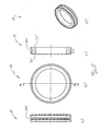
- Fig. 1 shows an inventive upper blade 7 in different views, which is designed to be placed on a harmonic 5 a cutting device 1 (see Fig. 4 ).
- the upper blade 7 differs from the known in the prior art upper blades by a circumferential groove 7 N, which serves as a driving engagement for a driver 130 (see Fig. 4 ) as described below.
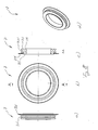
- Fig. 2 shows various views of a lower blade 11 according to the invention, which is designed to be arranged on a lower shaft 9 of the cutting device 1 (see Fig. 4 ).
- the lower blade 11 differs from the known in the art lower blades by a circumferential groove 11 N, which serves as a driving engagement for a driver 13U (see Fig. 4 ) as described below.
- Fig. 3 shows a disc knife pair 3, consisting of an upper blade 7 and a lower blade 11, in different views, the upper blade 7 and the lower blade 11 are in a cutting engagement, as it is made for example in the cutting device 1, when the outer blade 7 on the upper shaft 5 and the lower blade 11 is located on the lower shaft 9 in order to cut a passing through the cutting device 1 web material in strips.
- Fig. 4 shows the arranged on the upper shaft 5 upper blade 7 in cutting engagement with the arranged on the lower shaft 9 lower blade 11.
- the shafts 5, 9 is associated with a respective linear stage 250, 25U, which runs parallel to the associated shaft 5, 9.
- a driver 130, 13U On each linear stage 250, 25U, a driver 130, 13U is arranged so as to be longitudinally displaceable, wherein the positioning of the drivers 130, 13U takes place along the respective linear stage 250, 25U by means of a control (not shown).
- Fig. 5 shows the linear stage 25U with the driver 13U arranged thereon in a perspective view, but the linear table 250 and the driver 130 are each identical in construction.
- the cam 13U has a cam plate 13M which forms, along a peripheral portion, an engaging lip 13E which is substantially semicircular.
- the driver plate 13 M is by means of two Linerhubzylinder 27 in the vertical direction (in Fig. 5 from top to bottom) to raise and lower the engagement lip 13E relative to the stage 25U.
- the Linearhubzylinder 27 of the driver 13U are preferably each a pneumatic cylinder, and the activation of the Linearhubzylinder 27 is set by the controller, not shown.
- the lower blade 11 can be appropriately positioned along the lower shaft 9 by engaging the engaging lip 13E of the driver 13U with the groove 11N in the lower blade 11 by appropriately sliding the driver 13U along the linear table 25U and lifting it and lowering the engaging lip 13E by means of the Linearhubzylinder 27th
- Fig. 4 shows a storage area 17 of the cutting device 1, in which on the shafts 5, 9 arranged and not required for a current cutting operation knives 7, 11 may be arranged.
- the knives 7, 11 are arranged side by side in the storage area 17 so that they rest against each other and a knife pushed first into the storage area 17 bears against a stop 15 of the shafts 5, 9.
- the controller moves the dogs 130, 13U to an end of the shafts 5, 9 opposite the storage area 17 and activates the linear lifting cylinders 27 so that the engaging lip 13E is moved closer to the associated shaft 5, 9 than for engagement with a groove 7N, 11N is necessary.
- the control activates the linear stages 250, 25U in such a way that the drivers 130, 13U are displaced in the direction of the storage area 17.
- each driver plate 13M eventually strikes a side surface 7S of the upper blade 7 or a side surface 11S of the lower blade 11, and with a further displacement of the drivers 130, 13U in the direction of the storage region 17, all the knives 7, 11 become in the storage area 17 postponed.
- the marker 19 may be a bar mark on the shaft 5, 9 (perpendicular to the longitudinal axis) or may be formed by a laser pointer directed to the center of the shaft 5, 9 to align the groove 7N, 11N at a laser spot.
- a shifting force increases, which must apply the linear stage 250, 25U to move the knives 7, 11 in the storage area 17, as more and more knives 7, 11 through the Driver 130, 13U are moved while they move in the direction of the storage area 17.
- a pressure sensor 21 is arranged, which is in connection with the displacement control to determine the displacement force of the driver 130, 13U, while the drivers 130, 13U are moved in the direction of the storage area 17.
- a servo drive is used, which is to operate switchable between a speed control and a torque control.
- a further displacement finally proposes a rear side in the direction of displacement 7S, 11S of the first deferred knife 7, 11 to the stop 15 of the respective shaft 5, 9, whereby the measured by the pressure sensor 21 displacement force steadily increases, although the drivers 130, 13U do not move further in the direction of the storage area 17.
- the controller detects this situation (or exceeding a predetermined pressure force threshold) and stops moving the drivers 130, 13U.
- the drive current is monitored for the exceeding of a maximum value or determined at a torque control of the standstill by monitoring the position reporting signals.
- the knives 7, 11 are now arranged next to each other and abut each other, wherein a side surface of a first pushed on the shafts 5, 9 knife rests against the respective stop 15 of the shafts 5, 9. This standstill position is detected and stored by the control device.
- the controller calculates a total knife width MGL of the knives 7, 11 lined up, that is, the controller determines a distance between the drivers 130, 13U to the respective stop 15 of the associated shaft, 5, 9.
- the controller Since the controller knows the width of the knives 7, 11, the controller can calculate the number of knives 7, 11 on the associated shaft 5, 9 based on the total width of the knife MGL.
- the controller can also calculate the position of the grooves 7N, 11N of the knives 7, 11 on the shaft 5, 9.
- the controller then reverses the direction of displacement of the driver 13U, and six lower blades 11 are ejected from the storage area 17.
- the lower blade 11 engaged with the engaging lip 13E of the driver 13U is displaced along the lower shaft 9 until it has reached the desired position on the lower shaft 9.
- the knives 7, 11 are pushed individually out of the storage area 17 and suitably positioned.
- the cutting device 1 has only one linear stage with a driver which is movable between the upper shaft 5 and the lower shaft 9 in order to position the knives 7, 11.
- a linear table can, for example, be movable along a U-shaped path, wherein a shaft 5, 9 is arranged on each of the free legs of the U-shape.
- At least one radial lifting cylinder is advantageously arranged at the ends of at least one shaft 5, 9 in order to increase a mutual spacing of the shafts 5, 9, whereby the shafts 5, 9 are arranged relative to one another in a cutting position in which the upper knives 7 are in cutting engagement with the lower knives 11, and the shafts 5, 9 can be arranged on the other hand in a displacement position in which the upper knives 7 are not in cutting engagement with the lower knives 11 and independently along the respective shaft 5, 9 can be moved by the driver 130, 13U.
- the Radialhubzylinder the at least one shaft 5, 9 solve the knives 7, 11 thus before positioning them from their cutting engagement by moving the shafts 5, 9 in the traversing position for positioning the knives. After the positioning of the knives, the radial lifting cylinders move the shafts 5, 9 back into the cutting position, so that the upper knives 7 are in cutting engagement with the lower knife 11 in order to cut web material into strips.
- the Radialhubzylindern is preferably assigned in each case a Axialhubzylinder to adjust before performing the radial offset an axial displacement of the shafts 5, 9 in the longitudinal direction of the shafts 5, 9.
- a radial offset of the shafts is first set by means of Axialhubzylinder to move the shafts 5, 9 from the cutting position to the displacement position.
- the control moves the drivers 130, 13U against the respective stop 15 and reverses the direction of displacement of the respective driver 130, 13U, so that all the knives 7, 11 contact the End of the shaft 5, 9 are pushed, which is opposite to the storage area 17. Since the control of the number of knives 7, 11 on the respective shaft 5, 9 known, the displacement of the driver 130, 13U is stopped in time, so that the last deferred knife 7, 11 in a defined small distance from the free end the respective shaft 5, 9, which is opposite to the storage area 17.
- the knives 7, 11 are to be arranged differently at the end of a cutting process for a subsequent cutting operation, that is to say the number and / or the position of the knives 7, 11 are changed, the above-described steps for positioning the knives 7, 11 are repeated, that is, the sliding of all knives 7, 11 in the storage area 17 and the subsequent repositioning of the required knives 7, 11.
- the knives 7, 11 are fixed in a known manner on the respective shaft 5, 9, for example by a positive connection or a frictional connection.
- a positive connection can be achieved, for example, in that a wedge running along the longitudinal axis of the shaft 5, 9 in a groove is pressed by means of compressed air into a notch formed in the knives 7, 11. If no corresponding indentation is formed in the knives 7, 11, then there is a frictional connection between the wedge and the knives 7, 11.
- a plurality of longitudinally extending wedges may be provided, which preferably have a uniform angular offset with each other, in order to achieve the best possible adhesion between the shafts 5, 9 and the knives 7, 11.
- the shafts 5, 9 can rotate during the positioning of the knives 7, 11.
- the shafts 5, 9 are therefore advantageously associated with a cleaning device for the knives 7, 11 in order to free the side surfaces 7S, 11S from dust and the like.
- the cleaning means may be constituted, for example, by compressed air nozzles arranged at regular intervals along the longitudinal direction of the shafts 5, 9 to blow dust and the like from the side surfaces 7S, 11S of the knives 7, 11, preferably before performing the radial displacement of the shafts 5, 9.
- the cleaning device may alternatively or additionally be associated with the drivers 130 and 13U, which have, for example, compressed-air nozzles for cleaning the blades 7, 11 along the engagement lip 13E.
- the knives 7, 11 can be cleaned by moving the dogs 130, 13U along the entire length of the shafts 5, 9 to clean the knives 7, 11.
- the cleaning device can also be formed in the form of brushes or a rubber lip on the drivers 130, 13U, which mechanically clean the side surfaces 7S, 11S of the knives 7, 11 when the drivers 130, 13U come into engagement with the respective knives 7, 11 ,
- the knives 7, 11 may each have a spacer 7A, 11A in order to set a mutual distance between the knives 7, 11.
- Fig. 7 shows in different views an upper blade 7, the upper blade of the Fig. 1 to the fact that this additionally has a spacer 7A in the form of a circumferential spacer ring.
- Cutting dust accumulating during cutting of the continuous web material is deposited on the spacer 7A and can not protrude axially beyond the spacer 7A since otherwise it would fall off the upper blade 7. In this way it is ensured that the mutual distance between upper blades 7 is predetermined solely by the spacer 7A.
- Fig. 8 shows a variant of the upper blade 7 of Fig. 7 in which the spacer 7A is disposed on an opposite side surface 7S.
- the spacer 7A and a cutting blade 7K of the upper blade 7 are thus arranged on opposite side surfaces 7S of the upper blade 7.
- Fig. 9 shows various views of a lower blade 11, the lower blade of the Fig. 2 to the extent that it has a spacer 11A.
- the spacer 11A is in turn formed as a circumferential spacer ring.
- the spacers 7 A, 11 A of Fig. 7 to 9 are each shown as a circumferential spacer ring.
- the spacers 7A, 11A may each be formed by offset-spaced spacers, for example by four spacer tabs, which are arranged at an angular offset of 90 ° to each other on a side surface 7S, 11S.
- spacers 7A are used in the upper knives, spacers 11A need not necessarily be used on the lower knives, and vice versa.
- the described knives 7, 11 can first be pushed onto a shaft 5, 9 both with the one side surface 7S, 11S and also with the opposite side surface 7S, 11S, that is to say they can be used on both sides.
- the control since the grooves 7N, 11N of the knives 7, 11 are arranged asymmetrically, the control must be entered before positioning the knives 7, 11 of the control device in which orientation they have been slid to match the position of the grooves 7N, 11N calculated.
Landscapes
- Life Sciences & Earth Sciences (AREA)
- Forests & Forestry (AREA)
- Engineering & Computer Science (AREA)
- Mechanical Engineering (AREA)
- Nonmetal Cutting Devices (AREA)
- Finish Polishing, Edge Sharpening, And Grinding By Specific Grinding Devices (AREA)
- Details Of Cutting Devices (AREA)
- Dicing (AREA)
- Making Paper Articles (AREA)
Priority Applications (1)
| Application Number | Priority Date | Filing Date | Title |
|---|---|---|---|
| PL07033571T PL1932634T3 (pl) | 2006-11-27 | 2007-11-23 | Sposób pozycjonowania noży krajarki i odpowiednia doń krajarka |
Applications Claiming Priority (1)
| Application Number | Priority Date | Filing Date | Title |
|---|---|---|---|
| DE102006055902A DE102006055902A1 (de) | 2006-11-27 | 2006-11-27 | Verfahren zum Positionieren von Messern einer Schneidvorrichtung und zugehörige Schneidvorrichtung |
Publications (3)
| Publication Number | Publication Date |
|---|---|
| EP1932634A2 true EP1932634A2 (fr) | 2008-06-18 |
| EP1932634A3 EP1932634A3 (fr) | 2008-07-30 |
| EP1932634B1 EP1932634B1 (fr) | 2009-08-19 |
Family
ID=39111307
Family Applications (1)
| Application Number | Title | Priority Date | Filing Date |
|---|---|---|---|
| EP07033571A Not-in-force EP1932634B1 (fr) | 2006-11-27 | 2007-11-23 | Procédé de positionnement de couteaux d'un dispositif de coupe et dispositif de coupe correspondant |
Country Status (5)
| Country | Link |
|---|---|
| EP (1) | EP1932634B1 (fr) |
| AT (1) | ATE439955T1 (fr) |
| DE (2) | DE102006055902A1 (fr) |
| ES (1) | ES2328867T3 (fr) |
| PL (1) | PL1932634T3 (fr) |
Cited By (4)
| Publication number | Priority date | Publication date | Assignee | Title |
|---|---|---|---|---|
| EP2669225A1 (fr) * | 2012-05-29 | 2013-12-04 | Düspohl Maschinenbau GmbH | Enrouleur et installation de coupe longitudinale avec enrouleur |
| CN109700109A (zh) * | 2018-11-29 | 2019-05-03 | 温州法派服饰股份有限公司 | 一种滚压裁剪一体机 |
| CN119115049A (zh) * | 2024-11-12 | 2024-12-13 | 沧州中拓冷弯成型设备有限公司 | 一种自动调节板带横向宽度的纵剪机及其使用方法 |
| CN120964504A (zh) * | 2025-10-23 | 2025-11-18 | 温州万润机械有限公司 | 高速纸张分切机 |
Families Citing this family (1)
| Publication number | Priority date | Publication date | Assignee | Title |
|---|---|---|---|---|
| DE102018206641A1 (de) * | 2018-04-27 | 2019-10-31 | Robert Bosch Gmbh | Vorrichtung und Verfahren zum Schneiden eines Produkts, insbesondere aus Süßwarenmasse |
Citations (1)
| Publication number | Priority date | Publication date | Assignee | Title |
|---|---|---|---|---|
| DE10023210A1 (de) | 2000-05-12 | 2001-11-15 | Bilstein Spezialfab Wilhelm | Verfahren zur Positionierung von Untermessern an einer Einrichtung zum Längsteilen einer Materialbahn |
Family Cites Families (10)
| Publication number | Priority date | Publication date | Assignee | Title |
|---|---|---|---|---|
| CA1076020A (fr) * | 1977-10-20 | 1980-04-22 | Rengo Co. | Appareil de positionnement d'outils |
| CA1180428A (fr) * | 1980-11-13 | 1985-01-02 | Masateru Tokuno | Methode et dispositif de positionnement d'outils |
| FR2643586B1 (fr) * | 1989-02-24 | 1991-05-03 | Martin Sa | Dispositif de decalage de la position laterale d'un outil dans la station d'encochage au sein d'une machine usinant des elements en plaque |
| US5378221A (en) * | 1992-10-23 | 1995-01-03 | Corrugated Gear & Sprocket, Inc. | Assembly and method for axially aligning slotting, trimming, scoring or like heads |
| JP3980678B2 (ja) * | 1996-03-08 | 2007-09-26 | 富士フイルム株式会社 | 刃物位置切り替え制御方法 |
| FR2798878B1 (fr) * | 1999-09-24 | 2001-11-02 | Eastman Kodak Co | Dispositif et procede pour positionner un couteau par rapport a son contre-couteau |
| EP1319480A1 (fr) * | 2001-12-11 | 2003-06-18 | Wilhelm Bilstein KG Spezialfabrik für Maschinenmesser und Kompressorventile | Méthode ainsi que dispositif pour positionner par bloc des supports de couteau d'une coupeuse-bobineuse |
| US20050061121A1 (en) * | 2003-09-23 | 2005-03-24 | David Lauderbaugh | Bushings with sacrificial end caps and shims for axially positioning rotating slotting and scoring wheels |
| DE202005001726U1 (de) * | 2005-02-03 | 2005-05-19 | Wilhelm Bilstein KG Spezialfabrik für Maschinenmesser und Kompressorventile | Einrichtung zum Positionieren von Schneidwerkzeugen in Längsschneidemaschinen |
| DE202005003120U1 (de) * | 2005-02-26 | 2005-05-04 | Wilhelm Bilstein KG Spezialfabrik für Maschinenmesser und Kompressorventile | Bremseinrichtung zur Positionierung von Schneidwerkzeugen in Längsschneidemaschinen |
-
2006
- 2006-11-27 DE DE102006055902A patent/DE102006055902A1/de not_active Ceased
-
2007
- 2007-11-23 AT AT07033571T patent/ATE439955T1/de active
- 2007-11-23 EP EP07033571A patent/EP1932634B1/fr not_active Not-in-force
- 2007-11-23 ES ES07033571T patent/ES2328867T3/es active Active
- 2007-11-23 DE DE502007001340T patent/DE502007001340D1/de active Active
- 2007-11-23 PL PL07033571T patent/PL1932634T3/pl unknown
Patent Citations (1)
| Publication number | Priority date | Publication date | Assignee | Title |
|---|---|---|---|---|
| DE10023210A1 (de) | 2000-05-12 | 2001-11-15 | Bilstein Spezialfab Wilhelm | Verfahren zur Positionierung von Untermessern an einer Einrichtung zum Längsteilen einer Materialbahn |
Cited By (4)
| Publication number | Priority date | Publication date | Assignee | Title |
|---|---|---|---|---|
| EP2669225A1 (fr) * | 2012-05-29 | 2013-12-04 | Düspohl Maschinenbau GmbH | Enrouleur et installation de coupe longitudinale avec enrouleur |
| CN109700109A (zh) * | 2018-11-29 | 2019-05-03 | 温州法派服饰股份有限公司 | 一种滚压裁剪一体机 |
| CN119115049A (zh) * | 2024-11-12 | 2024-12-13 | 沧州中拓冷弯成型设备有限公司 | 一种自动调节板带横向宽度的纵剪机及其使用方法 |
| CN120964504A (zh) * | 2025-10-23 | 2025-11-18 | 温州万润机械有限公司 | 高速纸张分切机 |
Also Published As
| Publication number | Publication date |
|---|---|
| PL1932634T3 (pl) | 2010-01-29 |
| ES2328867T3 (es) | 2009-11-18 |
| EP1932634B1 (fr) | 2009-08-19 |
| DE102006055902A1 (de) | 2008-07-31 |
| EP1932634A3 (fr) | 2008-07-30 |
| DE502007001340D1 (de) | 2009-10-01 |
| ATE439955T1 (de) | 2009-09-15 |
Similar Documents
| Publication | Publication Date | Title |
|---|---|---|
| DE3613316C1 (de) | Vorrichtung zum Schneiden von gestapeltem,blattfoermigem Gut | |
| DE2844569C2 (de) | Werkzeugpositioniereinrichtung zum Positionieren einer Vielzahl von Werkzeugpaaren | |
| DE10313774B4 (de) | Vorrichtung zur Verarbeitung einer laufenden Materialbahn | |
| EP3453501B1 (fr) | Dispositif coupe-joint | |
| EP3678851B1 (fr) | Dispositif et procédé de fabrication pour la déposition des rubans de fibres | |
| EP2243606A2 (fr) | Installation de fabrication de plaques en lamelles de bois et procédé destiné à la fabrication de telles plaques | |
| EP1932634B1 (fr) | Procédé de positionnement de couteaux d'un dispositif de coupe et dispositif de coupe correspondant | |
| DE2606207A1 (de) | Vorrichtung zum perforieren von gewelltem rohr | |
| EP0910248B1 (fr) | Procede, dispositif et outil de decoupage pour la production de morceaux de pate individuels a partir d'une bande de pate continue | |
| DE102008033776A1 (de) | Wellpappe-Anlage | |
| DE2745693C2 (de) | Vorrichtung zum Zuführen geschuppter Wellpappebogen zu einer Stapelvorrichtung | |
| DE3613315A1 (de) | Anordnung zum zufuehren von gestapeltem, blattfoermigen gut zu einer weiterverarbeitungsstation, insbesondere schneidstation | |
| DE2702724C2 (de) | Einrichtung zum Sortieren und Ablegen von Zuschnitten bei Plattenaufteilanlagen | |
| DE3447703C2 (de) | Kontinuierlich arbeitende einseitige Format- und Kantenbearbeitungsmaschine | |
| DE19720689A1 (de) | Verfahren und Vorrichtung sowie Stanzwerkzeug zur Herstellung von einzelnen Teigstücken aus seiner kontinuierlichen Teigbahn | |
| EP2481540B1 (fr) | Dispositif de sciage d'au moins deux pièces usinées sous forme de plaques ou de piles de plaques | |
| DE19936213A1 (de) | Schneidmaschine für laibförmige Produkte | |
| EP1724077B1 (fr) | Dispositif de coupe longitudinale ayant des moyens de réglage des couteaux supérieurs et inférieurs | |
| EP0811439B1 (fr) | Dispositif pour la perforation des tôles | |
| DE2913786C3 (de) | Eingabetisch | |
| DE20306776U1 (de) | Einrichtung zum Querschneiden von Blech- oder Kunststoffbahnen | |
| DE3836503A1 (de) | Verfahren zum positionieren von werkzeugen einer laengsschneide- und/oder rillmaschine sowie vorrichtung zur durchfuehrung dieses verfahrens | |
| DD145011A3 (de) | Einrichtung zum entstapeln magneti ierbarer bleche | |
| WO2019037896A1 (fr) | Dispositif de coupe longitudinale | |
| EP4107004B1 (fr) | Système d'imprimante |
Legal Events
| Date | Code | Title | Description |
|---|---|---|---|
| PUAI | Public reference made under article 153(3) epc to a published international application that has entered the european phase |
Free format text: ORIGINAL CODE: 0009012 |
|
| AK | Designated contracting states |
Kind code of ref document: A2 Designated state(s): AT BE BG CH CY CZ DE DK EE ES FI FR GB GR HU IE IS IT LI LT LU LV MC MT NL PL PT RO SE SI SK TR |
|
| AX | Request for extension of the european patent |
Extension state: AL BA HR MK RS |
|
| PUAL | Search report despatched |
Free format text: ORIGINAL CODE: 0009013 |
|
| AK | Designated contracting states |
Kind code of ref document: A3 Designated state(s): AT BE BG CH CY CZ DE DK EE ES FI FR GB GR HU IE IS IT LI LT LU LV MC MT NL PL PT RO SE SI SK TR |
|
| AX | Request for extension of the european patent |
Extension state: AL BA HR MK RS |
|
| RIC1 | Information provided on ipc code assigned before grant |
Ipc: B26D 1/24 20060101AFI20080423BHEP Ipc: B26D 5/02 20060101ALI20080624BHEP Ipc: B26D 7/26 20060101ALI20080624BHEP Ipc: B65H 35/02 20060101ALI20080624BHEP |
|
| 17P | Request for examination filed |
Effective date: 20090113 |
|
| GRAP | Despatch of communication of intention to grant a patent |
Free format text: ORIGINAL CODE: EPIDOSNIGR1 |
|
| AKX | Designation fees paid |
Designated state(s): AT BE BG CH CY CZ DE DK EE ES FI FR GB GR HU IE IS IT LI LT LU LV MC MT NL PL PT RO SE SI SK TR |
|
| GRAS | Grant fee paid |
Free format text: ORIGINAL CODE: EPIDOSNIGR3 |
|
| GRAA | (expected) grant |
Free format text: ORIGINAL CODE: 0009210 |
|
| AK | Designated contracting states |
Kind code of ref document: B1 Designated state(s): AT BE BG CH CY CZ DE DK EE ES FI FR GB GR HU IE IS IT LI LT LU LV MC MT NL PL PT RO SE SI SK TR |
|
| REG | Reference to a national code |
Ref country code: GB Ref legal event code: FG4D Free format text: NOT ENGLISH |
|
| REG | Reference to a national code |
Ref country code: CH Ref legal event code: EP |
|
| REG | Reference to a national code |
Ref country code: IE Ref legal event code: FG4D |
|
| REF | Corresponds to: |
Ref document number: 502007001340 Country of ref document: DE Date of ref document: 20091001 Kind code of ref document: P |
|
| REG | Reference to a national code |
Ref country code: ES Ref legal event code: FG2A Ref document number: 2328867 Country of ref document: ES Kind code of ref document: T3 |
|
| REG | Reference to a national code |
Ref country code: GR Ref legal event code: EP Ref document number: 20090402719 Country of ref document: GR |
|
| LTIE | Lt: invalidation of european patent or patent extension |
Effective date: 20090819 |
|
| PG25 | Lapsed in a contracting state [announced via postgrant information from national office to epo] |
Ref country code: IS Free format text: LAPSE BECAUSE OF FAILURE TO SUBMIT A TRANSLATION OF THE DESCRIPTION OR TO PAY THE FEE WITHIN THE PRESCRIBED TIME-LIMIT Effective date: 20091219 Ref country code: LT Free format text: LAPSE BECAUSE OF FAILURE TO SUBMIT A TRANSLATION OF THE DESCRIPTION OR TO PAY THE FEE WITHIN THE PRESCRIBED TIME-LIMIT Effective date: 20090819 Ref country code: FI Free format text: LAPSE BECAUSE OF FAILURE TO SUBMIT A TRANSLATION OF THE DESCRIPTION OR TO PAY THE FEE WITHIN THE PRESCRIBED TIME-LIMIT Effective date: 20090819 Ref country code: SE Free format text: LAPSE BECAUSE OF FAILURE TO SUBMIT A TRANSLATION OF THE DESCRIPTION OR TO PAY THE FEE WITHIN THE PRESCRIBED TIME-LIMIT Effective date: 20090819 |
|
| PGFP | Annual fee paid to national office [announced via postgrant information from national office to epo] |
Ref country code: AT Payment date: 20091111 Year of fee payment: 3 |
|
| REG | Reference to a national code |
Ref country code: PL Ref legal event code: T3 |
|
| PG25 | Lapsed in a contracting state [announced via postgrant information from national office to epo] |
Ref country code: SI Free format text: LAPSE BECAUSE OF FAILURE TO SUBMIT A TRANSLATION OF THE DESCRIPTION OR TO PAY THE FEE WITHIN THE PRESCRIBED TIME-LIMIT Effective date: 20090819 Ref country code: LV Free format text: LAPSE BECAUSE OF FAILURE TO SUBMIT A TRANSLATION OF THE DESCRIPTION OR TO PAY THE FEE WITHIN THE PRESCRIBED TIME-LIMIT Effective date: 20090819 |
|
| REG | Reference to a national code |
Ref country code: IE Ref legal event code: FD4D |
|
| PG25 | Lapsed in a contracting state [announced via postgrant information from national office to epo] |
Ref country code: PT Free format text: LAPSE BECAUSE OF FAILURE TO SUBMIT A TRANSLATION OF THE DESCRIPTION OR TO PAY THE FEE WITHIN THE PRESCRIBED TIME-LIMIT Effective date: 20091221 Ref country code: CY Free format text: LAPSE BECAUSE OF FAILURE TO SUBMIT A TRANSLATION OF THE DESCRIPTION OR TO PAY THE FEE WITHIN THE PRESCRIBED TIME-LIMIT Effective date: 20090819 Ref country code: BG Free format text: LAPSE BECAUSE OF FAILURE TO SUBMIT A TRANSLATION OF THE DESCRIPTION OR TO PAY THE FEE WITHIN THE PRESCRIBED TIME-LIMIT Effective date: 20091119 |
|
| PG25 | Lapsed in a contracting state [announced via postgrant information from national office to epo] |
Ref country code: IE Free format text: LAPSE BECAUSE OF FAILURE TO SUBMIT A TRANSLATION OF THE DESCRIPTION OR TO PAY THE FEE WITHIN THE PRESCRIBED TIME-LIMIT Effective date: 20090819 Ref country code: DK Free format text: LAPSE BECAUSE OF FAILURE TO SUBMIT A TRANSLATION OF THE DESCRIPTION OR TO PAY THE FEE WITHIN THE PRESCRIBED TIME-LIMIT Effective date: 20090819 Ref country code: RO Free format text: LAPSE BECAUSE OF FAILURE TO SUBMIT A TRANSLATION OF THE DESCRIPTION OR TO PAY THE FEE WITHIN THE PRESCRIBED TIME-LIMIT Effective date: 20090819 Ref country code: EE Free format text: LAPSE BECAUSE OF FAILURE TO SUBMIT A TRANSLATION OF THE DESCRIPTION OR TO PAY THE FEE WITHIN THE PRESCRIBED TIME-LIMIT Effective date: 20090819 Ref country code: CZ Free format text: LAPSE BECAUSE OF FAILURE TO SUBMIT A TRANSLATION OF THE DESCRIPTION OR TO PAY THE FEE WITHIN THE PRESCRIBED TIME-LIMIT Effective date: 20090819 |
|
| PG25 | Lapsed in a contracting state [announced via postgrant information from national office to epo] |
Ref country code: SK Free format text: LAPSE BECAUSE OF FAILURE TO SUBMIT A TRANSLATION OF THE DESCRIPTION OR TO PAY THE FEE WITHIN THE PRESCRIBED TIME-LIMIT Effective date: 20090819 |
|
| PLBE | No opposition filed within time limit |
Free format text: ORIGINAL CODE: 0009261 |
|
| STAA | Information on the status of an ep patent application or granted ep patent |
Free format text: STATUS: NO OPPOSITION FILED WITHIN TIME LIMIT |
|
| PG25 | Lapsed in a contracting state [announced via postgrant information from national office to epo] |
Ref country code: MC Free format text: LAPSE BECAUSE OF NON-PAYMENT OF DUE FEES Effective date: 20091130 |
|
| 26N | No opposition filed |
Effective date: 20100520 |
|
| REG | Reference to a national code |
Ref country code: FR Ref legal event code: ST Effective date: 20100730 |
|
| PG25 | Lapsed in a contracting state [announced via postgrant information from national office to epo] |
Ref country code: FR Free format text: LAPSE BECAUSE OF NON-PAYMENT OF DUE FEES Effective date: 20091130 |
|
| PGFP | Annual fee paid to national office [announced via postgrant information from national office to epo] |
Ref country code: PL Payment date: 20101028 Year of fee payment: 4 |
|
| PGFP | Annual fee paid to national office [announced via postgrant information from national office to epo] |
Ref country code: GR Payment date: 20101014 Year of fee payment: 4 |
|
| PG25 | Lapsed in a contracting state [announced via postgrant information from national office to epo] |
Ref country code: LU Free format text: LAPSE BECAUSE OF NON-PAYMENT OF DUE FEES Effective date: 20091123 Ref country code: MT Free format text: LAPSE BECAUSE OF FAILURE TO SUBMIT A TRANSLATION OF THE DESCRIPTION OR TO PAY THE FEE WITHIN THE PRESCRIBED TIME-LIMIT Effective date: 20090819 |
|
| PG25 | Lapsed in a contracting state [announced via postgrant information from national office to epo] |
Ref country code: HU Free format text: LAPSE BECAUSE OF FAILURE TO SUBMIT A TRANSLATION OF THE DESCRIPTION OR TO PAY THE FEE WITHIN THE PRESCRIBED TIME-LIMIT Effective date: 20100220 |
|
| PG25 | Lapsed in a contracting state [announced via postgrant information from national office to epo] |
Ref country code: TR Free format text: LAPSE BECAUSE OF FAILURE TO SUBMIT A TRANSLATION OF THE DESCRIPTION OR TO PAY THE FEE WITHIN THE PRESCRIBED TIME-LIMIT Effective date: 20090819 |
|
| PG25 | Lapsed in a contracting state [announced via postgrant information from national office to epo] |
Ref country code: IT Free format text: LAPSE BECAUSE OF NON-PAYMENT OF DUE FEES Effective date: 20101123 |
|
| PGFP | Annual fee paid to national office [announced via postgrant information from national office to epo] |
Ref country code: IT Payment date: 20101130 Year of fee payment: 4 |
|
| PGFP | Annual fee paid to national office [announced via postgrant information from national office to epo] |
Ref country code: NL Payment date: 20111117 Year of fee payment: 5 Ref country code: ES Payment date: 20111216 Year of fee payment: 5 |
|
| PGFP | Annual fee paid to national office [announced via postgrant information from national office to epo] |
Ref country code: BE Payment date: 20111114 Year of fee payment: 5 |
|
| PGFP | Annual fee paid to national office [announced via postgrant information from national office to epo] |
Ref country code: DE Payment date: 20111202 Year of fee payment: 5 |
|
| REG | Reference to a national code |
Ref country code: CH Ref legal event code: PL |
|
| PG25 | Lapsed in a contracting state [announced via postgrant information from national office to epo] |
Ref country code: CH Free format text: LAPSE BECAUSE OF NON-PAYMENT OF DUE FEES Effective date: 20111130 Ref country code: LI Free format text: LAPSE BECAUSE OF NON-PAYMENT OF DUE FEES Effective date: 20111130 |
|
| BERE | Be: lapsed |
Owner name: DUSPOHL MASCHINENBAU G.M.B.H. Effective date: 20121130 |
|
| REG | Reference to a national code |
Ref country code: NL Ref legal event code: V1 Effective date: 20130601 |
|
| GBPC | Gb: european patent ceased through non-payment of renewal fee |
Effective date: 20121123 |
|
| PG25 | Lapsed in a contracting state [announced via postgrant information from national office to epo] |
Ref country code: NL Free format text: LAPSE BECAUSE OF NON-PAYMENT OF DUE FEES Effective date: 20130601 Ref country code: GR Free format text: LAPSE BECAUSE OF NON-PAYMENT OF DUE FEES Effective date: 20130604 Ref country code: IT Free format text: LAPSE BECAUSE OF NON-PAYMENT OF DUE FEES Effective date: 20121123 Ref country code: BE Free format text: LAPSE BECAUSE OF NON-PAYMENT OF DUE FEES Effective date: 20121130 |
|
| REG | Reference to a national code |
Ref country code: GR Ref legal event code: ML Ref document number: 20090402719 Country of ref document: GR Effective date: 20130604 |
|
| REG | Reference to a national code |
Ref country code: DE Ref legal event code: R119 Ref document number: 502007001340 Country of ref document: DE Effective date: 20130601 |
|
| PG25 | Lapsed in a contracting state [announced via postgrant information from national office to epo] |
Ref country code: DE Free format text: LAPSE BECAUSE OF NON-PAYMENT OF DUE FEES Effective date: 20130601 |
|
| PG25 | Lapsed in a contracting state [announced via postgrant information from national office to epo] |
Ref country code: GB Free format text: LAPSE BECAUSE OF NON-PAYMENT OF DUE FEES Effective date: 20121123 |
|
| REG | Reference to a national code |
Ref country code: AT Ref legal event code: MM01 Ref document number: 439955 Country of ref document: AT Kind code of ref document: T Effective date: 20121130 |
|
| PG25 | Lapsed in a contracting state [announced via postgrant information from national office to epo] |
Ref country code: AT Free format text: LAPSE BECAUSE OF NON-PAYMENT OF DUE FEES Effective date: 20121130 |
|
| PG25 | Lapsed in a contracting state [announced via postgrant information from national office to epo] |
Ref country code: PL Free format text: LAPSE BECAUSE OF NON-PAYMENT OF DUE FEES Effective date: 20121123 |
|
| REG | Reference to a national code |
Ref country code: PL Ref legal event code: LAPE |
|
| REG | Reference to a national code |
Ref country code: ES Ref legal event code: FD2A Effective date: 20140305 |
|
| PG25 | Lapsed in a contracting state [announced via postgrant information from national office to epo] |
Ref country code: ES Free format text: LAPSE BECAUSE OF NON-PAYMENT OF DUE FEES Effective date: 20121124 |