EP1932749B1 - Module terminal, en particulier module de fronts pour un véhicule, ainsi que procédé de montage d'un module terminal sur la carrosserie d'un véhicule - Google Patents
Module terminal, en particulier module de fronts pour un véhicule, ainsi que procédé de montage d'un module terminal sur la carrosserie d'un véhicule Download PDFInfo
- Publication number
- EP1932749B1 EP1932749B1 EP07020145A EP07020145A EP1932749B1 EP 1932749 B1 EP1932749 B1 EP 1932749B1 EP 07020145 A EP07020145 A EP 07020145A EP 07020145 A EP07020145 A EP 07020145A EP 1932749 B1 EP1932749 B1 EP 1932749B1
- Authority
- EP
- European Patent Office
- Prior art keywords
- headlamp
- support
- end module
- motor vehicle
- module according
- Prior art date
- Legal status (The legal status is an assumption and is not a legal conclusion. Google has not performed a legal analysis and makes no representation as to the accuracy of the status listed.)
- Not-in-force
Links
- 230000002349 favourable effect Effects 0.000 description 3
- 239000000463 material Substances 0.000 description 3
- 238000005452 bending Methods 0.000 description 2
- MTCFGRXMJLQNBG-UHFFFAOYSA-N serine Chemical compound OCC(N)C(O)=O MTCFGRXMJLQNBG-UHFFFAOYSA-N 0.000 description 2
- 208000031872 Body Remains Diseases 0.000 description 1
- 241001522306 Serinus serinus Species 0.000 description 1
- 230000000295 complement effect Effects 0.000 description 1
- 230000006835 compression Effects 0.000 description 1
- 238000007906 compression Methods 0.000 description 1
- 238000005516 engineering process Methods 0.000 description 1
- 238000002347 injection Methods 0.000 description 1
- 239000007924 injection Substances 0.000 description 1
- 238000004519 manufacturing process Methods 0.000 description 1
- 230000003287 optical effect Effects 0.000 description 1
Images


Classifications
-
- B—PERFORMING OPERATIONS; TRANSPORTING
- B62—LAND VEHICLES FOR TRAVELLING OTHERWISE THAN ON RAILS
- B62D—MOTOR VEHICLES; TRAILERS
- B62D25/00—Superstructure or monocoque structure sub-units; Parts or details thereof not otherwise provided for
- B62D25/08—Front or rear portions
- B62D25/082—Engine compartments
- B62D25/084—Radiator supports
-
- B—PERFORMING OPERATIONS; TRANSPORTING
- B60—VEHICLES IN GENERAL
- B60Q—ARRANGEMENT OF SIGNALLING OR LIGHTING DEVICES, THE MOUNTING OR SUPPORTING THEREOF OR CIRCUITS THEREFOR, FOR VEHICLES IN GENERAL
- B60Q1/00—Arrangement of optical signalling or lighting devices, the mounting or supporting thereof or circuits therefor
- B60Q1/02—Arrangement of optical signalling or lighting devices, the mounting or supporting thereof or circuits therefor the devices being primarily intended to illuminate the way ahead or to illuminate other areas of way or environments
- B60Q1/04—Arrangement of optical signalling or lighting devices, the mounting or supporting thereof or circuits therefor the devices being primarily intended to illuminate the way ahead or to illuminate other areas of way or environments the devices being headlights
- B60Q1/0408—Arrangement of optical signalling or lighting devices, the mounting or supporting thereof or circuits therefor the devices being primarily intended to illuminate the way ahead or to illuminate other areas of way or environments the devices being headlights built into the vehicle body, e.g. details concerning the mounting of the headlamps on the vehicle body
- B60Q1/0416—Arrangement of optical signalling or lighting devices, the mounting or supporting thereof or circuits therefor the devices being primarily intended to illuminate the way ahead or to illuminate other areas of way or environments the devices being headlights built into the vehicle body, e.g. details concerning the mounting of the headlamps on the vehicle body the housing being mounted on the vehicle body using rails
-
- B—PERFORMING OPERATIONS; TRANSPORTING
- B60—VEHICLES IN GENERAL
- B60Q—ARRANGEMENT OF SIGNALLING OR LIGHTING DEVICES, THE MOUNTING OR SUPPORTING THEREOF OR CIRCUITS THEREFOR, FOR VEHICLES IN GENERAL
- B60Q1/00—Arrangement of optical signalling or lighting devices, the mounting or supporting thereof or circuits therefor
- B60Q1/02—Arrangement of optical signalling or lighting devices, the mounting or supporting thereof or circuits therefor the devices being primarily intended to illuminate the way ahead or to illuminate other areas of way or environments
- B60Q1/04—Arrangement of optical signalling or lighting devices, the mounting or supporting thereof or circuits therefor the devices being primarily intended to illuminate the way ahead or to illuminate other areas of way or environments the devices being headlights
- B60Q1/0408—Arrangement of optical signalling or lighting devices, the mounting or supporting thereof or circuits therefor the devices being primarily intended to illuminate the way ahead or to illuminate other areas of way or environments the devices being headlights built into the vehicle body, e.g. details concerning the mounting of the headlamps on the vehicle body
- B60Q1/0441—Arrangement of optical signalling or lighting devices, the mounting or supporting thereof or circuits therefor the devices being primarily intended to illuminate the way ahead or to illuminate other areas of way or environments the devices being headlights built into the vehicle body, e.g. details concerning the mounting of the headlamps on the vehicle body the housing being fastened onto the vehicle body using means other than screws
Definitions
- the invention relates to a motor vehicle end module, in particular motor vehicle front end module, according to the preamble of patent claim 1.
- Front end modules with mounted headlamps and mounted bumper cover are attached to the respective vehicle body in an automatic front-end assembly.
- the front end module has in each case in the vehicle transverse direction projecting lower headlight carrier, which together with one upper carrier part form an open to the vehicle side frame surrounding the headlight.
- the upper carrier part is in each case integrally formed on the front end carrier.
- the headlamp is connected in a rigid attachment to the upper carrier part of the front end carrier.
- a front end module is known in which the headlight is attached via attachment points on a lower headlight carrier, but not on an upper headlight carrier.
- a front-end module for a motor vehicle is likewise known, in which laterally closed support frames, in which the headlamps are mounted, are provided on the front-end support. The headlights are not flexible, but firmly attached to the support frame.
- the front end module has a headlamp carrier as an inherently elastically deformable, separate component which is mounted on an end module mounting bracket.
- the headlight is fastened together with the body-side fender at a common reference mounting point on the headlight carrier.
- the common reference mounting point shall be located in a position favorable for both headlamp mounting and fender mounting. As a result, such a joint attachment is structurally complex.
- the object of the invention is to provide a motor vehicle end module, in particular a motor vehicle front end module, in which the headlights can be easily aligned with respect to the body.
- the headlamp carrier at least a first reference attachment point for attachment of the headlamp and at least one, spaced therefrom second reference attachment point for attachment of the vehicle body.
- both the first reference attachment point and the second reference attachment point can be arranged laterally spaced from each other in a position favorable for headlamp attachment or body attachment.
- Reference attachment points are such attachment points that allow a backlash-free positioning of the headlamp or the vehicle body in the reference position, in which the body and the headlamps are aligned in the correct position to each other with a uniform joint.
- the headlamp carrier may be formed elastically deformable.
- the headlamp carrier is not elastically deformable overall over its entire length, but has only a dimensional stability which is reduced compared to the remaining headlamp carrier sections at a compensation section. In this way, the headlamp carrier perform a tension-free length compensation in the vehicle longitudinal and / or transverse direction.
- the headlamp carrier between the two spaced reference points rigid, ie with one, with respect to the remaining headlamp sections significantly reduced elasticity may be formed. In this way it is ensured that, despite the reference points spaced from each other, the headlight and the vehicle body remain arranged in the correct position relative to one another.
- the compensation section can form a pivot axis in the manner of a film hinge, around which the carrier arm of the headlight carrier can be flexibly swiveled.
- the headlight can pivot in a defined manner about a pivot axis in order to compensate for body-side deviations.
- the compensation section can connect two carrier arms of the headlight carrier in an articulated manner. In terms of manufacturing technology, it is preferred if the compensation section connects the two carrier arms in the same material and in one piece.
- the compensation portion is in the form of an expandable or compressible leaf spring.
- the two parts of the compensation section can be pulled apart symmetrically or asymmetrically.
- the compensation section z. B assume a uniform elliptical shape, which is compressed or bulged. This means an expansion or compression only in the y-direction.
- the compensation section will rather assume an uneven elliptical shape (drop shape).
- the headlamp carrier can be connected via the one support arm on the front end support.
- the first and second reference attachment points for mounting the headlamp or the vehicle body can be arranged. In this way, it is certainly prevented that the first and second reference attachment points shift to each other.
- the headlamp beam according to the prior art is designed to be elastic in itself, without providing a predefined bending pivot axis or a compensation section. For this reason, the headlamp and the fender on a - in contrast to the invention - common reference mounting point on the headlamp carrier attached Serin. When using such, in itself elastically deformable headlamp carrier there is a risk that spaced apart first and second reference points can shift against each other.
- the end module may preferably have a centrally arranged front-end mounting carrier to which the headlight carrier is connected as a separate component. In this way, the headlamp carrier can also be slightly displaced relative to the front-end mounting bracket for tolerance compensation.
- the two support arms of the headlamp carrier can be formed with low elasticity, while the hinge portion has a comparatively high elasticity.
- the hinge portion may form the already mentioned pivot axis, which extends substantially in the vehicle vertical direction.
- the headlamp carrier For a stable attachment of the headlamp forms the headlamp carrier together with an upper support part open to the vehicle side frame surrounding the headlamp. In this way, the headlamp can be mounted in about a three-point bearing or in a four-point bearing between the upper support member and the headlamp carrier. There are also other multipoint bearings, such as a Beingticianlagerung conceivable.
- Fig. 1 is shown in a partial view from the front of a vehicle body with a fully assembled front end module.
- the front end module carries, inter alia, the partially illustrated bumper cover 1 and the headlight 3 and is known to be used in a modular design front side in the vehicle body.
- the headlight 3 is peripherally limited by the bumper cover 1, a front end of the body-side fender 5 and a front flap 7, and spaced by a headlight joint 9.
- the headlight joint 9 surrounds the headlight 3 with a uniform gap.
- the front-end module has a mounting frame 11 arranged centrally in the vehicle transverse direction y for receiving a cooler (not shown).
- the mounting frame 11 is formed as a plastic injection molded part, on the side of a retaining bracket 13 is integrally formed, on which a headlamp carrier 15 is fastened by means of indicated screw 17.
- the screw 17 can be realized by means of hollow screws, with the help of an additional tolerance compensation in the x, y and z directions is possible. In case that approximately the headlight joint 9 between the headlight 3 and the front flap 7 is wedge-shaped, can be corrected accordingly over these hollow screws of the joint profile.
- the headlamp carrier 15 is formed of two U-shaped rigid support arms 19 and 21, which are connected to each other via a hinge portion 22 or compensating portion in one piece and of the same material.
- the hinge section 22 or compensating section connects the two support arms 19 and 21 via spaced webs 24 with reduced material thickness.
- the webs 24 act as film hinges and allow a limited pivotal movement of the support arm 21 about the pivot axis S shown.
- the pivot axis S extends approximately in the z-direction. It is also possible that the compensating portion is formed in the manner of a leaf spring.
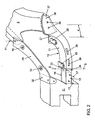
- T-slot guides 25 spaced apart from one another by way of example are formed as first reference attachment points, on which the headlight 3 with corresponding T-slots can be pushed forward into its reference position up to a stop 27.
- the headlight 3 may also be fastened via only a first reference attachment point 25.
- the headlamp 3 Due to the substantially play-free fit between the T-slot guides 25 and the complementary T-slots of the headlamp 3, the headlamp 3 is aligned in the reference position with very little tolerance almost free of play to the headlamp carrier 15. This reference position is secured by a not shown locking connection between the headlamp carrier 15 and the headlight 3.
- the headlight 3 may be provided with a positioning pin, not shown. In the pre-assembly of the headlamp 3 on the headlamp carrier 15, the positioning with a low tolerance in the in the Fig. 2 Positioning hole shown in the stop 27 are pushed. After the headlight 3 has been mounted on the headlight carrier 15, the headlight 3 is aligned in the x, y and z directions.
- the headlamp support 15 is associated with an upper support member 29 which is screwed at one end to an upper support bracket 30 of the mounting bracket 11 in the x-direction and z-direction and the other end on the top side via a mounting point 31 with the fender 5.
- the upper support part 29 has two further attachment points 34, 35 for fastening the headlamp 3.
- the headlight carrier 15 is formed at its free outer end with a cup-shaped surface stop 36, which is externally pushed onto a stop 37 formed complementarily of the fender 5.
- the two side stops 36, 37 are connected to each other via screw 38 as a second reference attachment points.
- the two first reference attachment points 25 for play-free and rigid attachment of the headlamp 3 and the two second reference attachment points 38 for attachment of the headlamp carrier 15 on the fender 5 are spaced from each other by a distance a each arranged in a favorable position for the respective headlight attachment or fender attachment.
- the headlamp carrier 15 on its support arm 21 two locking recesses 39, in which the bumper cover 1 can be latched. Additional connection points, not shown, for the bumper cover 1 are provided in the region of the surface stop 36 of the headlamp support 15.
- the headlight 3 is slid onto the T-slot guides 25, 26 and locked in its reference position.
- one of the two T-slot guides is basically sufficient, in particular the in FIG. 2 shown on the right.
- the headlight 3 is stapled via flexible tabs on the attachment points 34, 35 of the upper support member 29. Due to the flexible tabs of the headlight 3 and by stitching mechanical stresses in the region of the upper support member 29 can be prevented.
Landscapes
- Engineering & Computer Science (AREA)
- Mechanical Engineering (AREA)
- Chemical & Material Sciences (AREA)
- Combustion & Propulsion (AREA)
- Transportation (AREA)
- Lighting Device Outwards From Vehicle And Optical Signal (AREA)
- Automobile Manufacture Line, Endless Track Vehicle, Trailer (AREA)
- Body Structure For Vehicles (AREA)
Claims (10)
- Module d'extrémité avant de véhicule automobile doté d'au moins un support de phare (15) latéral au niveau duquel le phare (3) et la carrosserie d'un véhicule (5) épousent une position de référence dans laquelle la position du phare (3) et de la carrosserie d'un véhicule (5) est ajustée, le support de phare (15) comportant au moins un premier point de fixation de référence (25) pour fixer le phare (3) et au moins un deuxième point de fixation de référence (38) placé à une certaine distance (a) de celui-ci pour fixer la carrosserie d'un véhicule (5), et le support de phare (15) formant, conjointement avec une partie de support supérieure (29), un cadre ouvert sur le côté du véhicule, qui ceint le phare (3), caractérisé en ce que la partie de support supérieure (29) est vissée, dans la direction longitudinale et verticale du véhicule (x, z), avec une console d'immobilisation (30) supérieure d'un support d'extrémité avant (11) et que le phare (3) est fixé à au moins un point de fixation (34, 35) de la partie de support supérieure (29) via au moins une bride flexible.
- Module d'extrémité avant de véhicule automobile selon la revendication 1, caractérisé en ce que le support de phare (15) est réalisé entre les deux points de référence (25, 38) espacés de la distance (a), avec une élasticité pour l'essentiel réduite par rapport aux segments de support de phare restants.
- Module d'extrémité avant de véhicule automobile selon la revendication 1 ou 2, caractérisé en ce que le support de phare (15) comporte deux bras de support (19, 21) rigides reliés entre eux via un segment d'équilibrage (22) par le biais d'une unité de matériaux et d'une réalisation d'un seul tenant.
- Module d'extrémité avant de véhicule automobile selon la revendication 3, caractérisé en ce que les deux bras de support (19, 21) du support de phare (15) sont mobiles l'un par rapport à l'autre dans la direction transversale du véhicule (y) et/ou dans la direction longitudinale du véhicule (x).
- Module d'extrémité avant de véhicule automobile selon la revendication 3 ou 4, caractérisé en ce que le support de phare (15) peut être raccordé à un support d'extrémité avant (11) via un bras de support (19).
- Module d'extrémité avant de véhicule automobile selon la revendication 5, caractérisé en ce que les premier et deuxième points de fixation (25, 38) sont disposés au niveau de l'autre bras de,support (21).
- Module d'extrémité avant de véhicule automobile selon l'une quelconque des revendications précédentes, caractérisé en ce que le support de phare (15) prend la forme d'un élément séparé pouvant être monté au niveau du support d'extrémité avant (11).
- Module d'extrémité avant de véhicule automobile selon l'une quelconque des revendications 3 à 7, caractérisé en ce que le segment d'équilibrage (22) forme, comme une charnière pelliculée, un axe de pivotement (S) autour duquel le bras de support (21) du support de phare (15) peut pivoter de façon flexible.
- Module d'extrémité avant de véhicule automobile selon l'une quelconque des revendications 3 à 7, caractérisé en ce que le segment d'équilibrage (22) est réalisé sous la forme d'un ressort à lame permettant au bras de support (21) du support de phare (15) de varier en longueur.
- Module d'extrémité avant de véhicule automobile selon l'une quelconque des revendications précédentes, caractérisé en ce que le phare (3) est fixé dans un logement à quatre points positionné entre la partie de support supérieure (29) et le support de phare (15).
Applications Claiming Priority (1)
| Application Number | Priority Date | Filing Date | Title |
|---|---|---|---|
| DE102006058857A DE102006058857A1 (de) | 2006-12-13 | 2006-12-13 | Endmodul, insbesondere Frontendmodul für ein Fahrzeug sowie Verfahren zur Montage eines Endmoduls an eine Fahrzeugkarosserie |
Publications (2)
| Publication Number | Publication Date |
|---|---|
| EP1932749A1 EP1932749A1 (fr) | 2008-06-18 |
| EP1932749B1 true EP1932749B1 (fr) | 2010-03-17 |
Family
ID=38895610
Family Applications (1)
| Application Number | Title | Priority Date | Filing Date |
|---|---|---|---|
| EP07020145A Not-in-force EP1932749B1 (fr) | 2006-12-13 | 2007-10-15 | Module terminal, en particulier module de fronts pour un véhicule, ainsi que procédé de montage d'un module terminal sur la carrosserie d'un véhicule |
Country Status (3)
| Country | Link |
|---|---|
| EP (1) | EP1932749B1 (fr) |
| AT (1) | ATE461098T1 (fr) |
| DE (2) | DE102006058857A1 (fr) |
Cited By (2)
| Publication number | Priority date | Publication date | Assignee | Title |
|---|---|---|---|---|
| US12486962B1 (en) | 2025-03-21 | 2025-12-02 | Ford Global Technologies, Llc | Vehicle lamp assembly having T-shaped connector |
| DE102025110062A1 (de) | 2025-03-17 | 2026-04-02 | Audi Aktiengesellschaft | Führungsbauteileanordnung für eine Karosseriebauteilanordnung eines Fahrzeugs |
Families Citing this family (13)
| Publication number | Priority date | Publication date | Assignee | Title |
|---|---|---|---|---|
| DE102007016925A1 (de) * | 2007-04-05 | 2008-10-09 | Hbpo Gmbh | Frontendmodul und Montageverfahren |
| DE102008051290B4 (de) * | 2008-10-10 | 2021-05-27 | Volkswagen Ag | Anodnung zur Montage eines Frontend-Moduls an eine Rohbaukarosserie eines Fahrzeugs |
| DE102008059294A1 (de) * | 2008-11-27 | 2010-06-02 | Dr. Ing. H.C. F. Porsche Aktiengesellschaft | Beleuchtungseinrichtung für ein Kraftfahrzeug |
| DE102009001038A1 (de) * | 2009-02-20 | 2010-09-02 | Faurecia Kunststoffe Automobilsysteme Gmbh | Kraftfahrzeugfronteinheit |
| DE102009024783B4 (de) * | 2009-06-10 | 2018-10-31 | Rehau Ag + Co | Befestigungsanordnung einer Leuchteinheit an einem Verkleidungsteil |
| DE102009042415B4 (de) | 2009-09-21 | 2022-02-24 | Dr. Ing. H.C. F. Porsche Aktiengesellschaft | Personenkraftwagen |
| DE102010011230A1 (de) * | 2010-03-12 | 2011-09-15 | Audi Ag | Schweinwerfereinheit für ein Kraftfahrzeug mit einer Befestigungsvorrichtung |
| FR2980441B1 (fr) * | 2011-09-27 | 2015-05-29 | Peugeot Citroen Automobiles Sa | Support deformable de feu et de pare-choc pour rattrapage de jeu et montage isostatique. |
| EP2900518A1 (fr) * | 2012-09-25 | 2015-08-05 | Jaguar Land Rover Limited | Console de montage et procédé de support d'une structure |
| DE102012020795A1 (de) * | 2012-10-24 | 2014-04-24 | GM Global Technology Operations LLC (n. d. Ges. d. Staates Delaware) | Fahrzeugleuchte für den Einbau in eine Fahrzeugkarosserie |
| DE102020003461A1 (de) | 2020-06-09 | 2021-12-09 | Daimler Ag | Leuchte für ein Kraftfahrzeug |
| GB2612573B (en) * | 2021-10-20 | 2024-01-10 | Jaguar Land Rover Ltd | Vehicle front end alignment improvements |
| DE102024109603A1 (de) * | 2024-04-05 | 2025-10-09 | Bayerische Motoren Werke Aktiengesellschaft | Scheinwerfervorrichtung für ein Kraftfahrzeug und Kraftfahrzeug |
Family Cites Families (11)
| Publication number | Priority date | Publication date | Assignee | Title |
|---|---|---|---|---|
| JPH043880Y2 (fr) * | 1984-12-28 | 1992-02-05 | ||
| IT1307007B1 (it) * | 1999-01-26 | 2001-10-11 | Magneti Marelli Climat Srl | Gruppo frontale preassemblato per veicoli. |
| FR2820706B1 (fr) * | 2001-02-15 | 2003-05-16 | Faurecia Ind | Ensemble de bloc avant de vehicule automobile comportant un dispositif ameliore de fixation des composants, et vehicule equipe d'un tel ensemble |
| JP3628269B2 (ja) * | 2001-03-22 | 2005-03-09 | 日野自動車株式会社 | 車両用ヘッドランプの取付構造 |
| US6923495B2 (en) * | 2002-03-01 | 2005-08-02 | Nissan Motor Co., Ltd. | Automobile car body front construction and method of assembling car body front |
| FR2864013B1 (fr) * | 2003-12-19 | 2006-03-17 | Faurecia Bloc Avant | Ensemble de partie avant de vehicule automobile comportant des moyens perfectionnes de fixation et d'ajustement en position, et vehicule automobile pourvu d'un tel ensemble. |
| FR2873651B1 (fr) * | 2004-08-02 | 2006-11-24 | Faurecia Bloc Avant | Ensemble de bloc-avant pour un vehicule automobile |
| FR2873652B1 (fr) | 2004-08-02 | 2008-01-25 | Faurecia Bloc Avant | Ensemble de partie avant d'un vehicule automobile |
| FR2873649B1 (fr) * | 2004-08-02 | 2006-11-24 | Faurecia Bloc Avant | Ensemble de bloc-avant de vehicule automobile |
| DE102005013107B3 (de) * | 2005-03-18 | 2006-07-13 | Faurecia Kunststoffe Automobilsysteme Gmbh | Träger für die Fronteinheit eines Kraftfahrzeugs und Montageverfahren |
| DE102006039627B3 (de) * | 2006-08-24 | 2008-01-17 | Faurecia Kunststoffe Automobilsysteme Gmbh | Halterung für eine Scheinwerfereinheit, Verfahren zu deren Herstellung und Fronteinheit |
-
2006
- 2006-12-13 DE DE102006058857A patent/DE102006058857A1/de not_active Withdrawn
-
2007
- 2007-10-15 AT AT07020145T patent/ATE461098T1/de active
- 2007-10-15 DE DE502007003127T patent/DE502007003127D1/de active Active
- 2007-10-15 EP EP07020145A patent/EP1932749B1/fr not_active Not-in-force
Cited By (2)
| Publication number | Priority date | Publication date | Assignee | Title |
|---|---|---|---|---|
| DE102025110062A1 (de) | 2025-03-17 | 2026-04-02 | Audi Aktiengesellschaft | Führungsbauteileanordnung für eine Karosseriebauteilanordnung eines Fahrzeugs |
| US12486962B1 (en) | 2025-03-21 | 2025-12-02 | Ford Global Technologies, Llc | Vehicle lamp assembly having T-shaped connector |
Also Published As
| Publication number | Publication date |
|---|---|
| ATE461098T1 (de) | 2010-04-15 |
| DE102006058857A1 (de) | 2008-06-19 |
| DE502007003127D1 (de) | 2010-04-29 |
| EP1932749A1 (fr) | 2008-06-18 |
Similar Documents
| Publication | Publication Date | Title |
|---|---|---|
| EP1932749B1 (fr) | Module terminal, en particulier module de fronts pour un véhicule, ainsi que procédé de montage d'un module terminal sur la carrosserie d'un véhicule | |
| EP2024222B1 (fr) | Module pare-chocs | |
| EP0786398B1 (fr) | Structure d'une carrosserie d'un véhicule à moteur et gabarit de montage | |
| EP2152542B1 (fr) | Module d'extrémité avant pour véhicules | |
| EP3055165B1 (fr) | Procédé permettant le montage d'un module d'extrémité avant et d'un projecteur avant sur la carrosserie d'une voiture et ensemble de retenue d'un projecteur avant sur un module d'extrémité avant | |
| EP2057035B1 (fr) | Fixation pour une unité de phare, procédé de production associé et unité avant | |
| DE102013007896A1 (de) | Abstützanordnung eines Stoßfängers an einem Frontmodul eines Kraftwagens | |
| DE102008052966B4 (de) | Befestigungsanordnung an Fahrzeugen | |
| EP3275733B1 (fr) | Système de fixation de phares pour véhicules automobiles et procédé | |
| DE102009042415A1 (de) | Personenkraftwagen | |
| DE102007033313A1 (de) | Stoßfänger für einen Personenkraftwagen | |
| DE102006015399B4 (de) | Halteteil an einer Karosserie eines Kraftwagens | |
| DE102013207388B4 (de) | Trägersystem für einen Scheinwerfer eines Kraftfahrzeugs | |
| DE102016200452A1 (de) | Stützträger für ein Kraftfahrzeug, Anordnung eines Stützträgers an einem Montageträger, sowie Verfahren zur Ausrichtung eines mit einem Montageträger verbundenen Stützträgers | |
| DE102010022738A1 (de) | Kraftfahrzeugfrontend | |
| DE102008012667B4 (de) | Frontenmodul für ein Kraftfahrzeug sowie Verfahren zur Vormontage desselben | |
| DE10319442B4 (de) | Baugruppe, entsprechendes Rahmenmodul und entsprechende Rahmenstruktur | |
| DE102005012122A1 (de) | Dachmodul für ein Fahrzeug sowie Verfahren zur Montage eines solchen Dachmoduls | |
| DE102012023770A1 (de) | Montagevorrichtung zur Montage eines Halteelements für Anbauteile an einem Kraftfahr-zeug und Verfahren zur Montage von Anbauteilen an einem Kraftfahrzeug | |
| DE102015226051A1 (de) | Anordnung eines Scheinwerfers gegenüber einem rohbauseitig festgelegten Trägerelement sowie Verfahren zur Feinjustierung eines lösbar befestigten Scheinwerfers gegenüber einem rohbauseitig festgelegten Trägerelement eines Kraftfahrzeugs | |
| DE102021214378A1 (de) | Trägeranordnung für ein Kraftfahrzeug | |
| DE102010061034B4 (de) | Vorrichtung und Verfahren zum Befestigen eines Scheinwerfers | |
| WO2005080724A1 (fr) | Bras pour systeme de charniere pantographique | |
| DE102023003983B4 (de) | Fahrzeug, Außenhautbauteil und Außenhautsystem | |
| DE102005041216A1 (de) | Befestigungsanordnung von Außenbeplankungsteilen eines Kraftwagens |
Legal Events
| Date | Code | Title | Description |
|---|---|---|---|
| PUAI | Public reference made under article 153(3) epc to a published international application that has entered the european phase |
Free format text: ORIGINAL CODE: 0009012 |
|
| AK | Designated contracting states |
Kind code of ref document: A1 Designated state(s): AT BE BG CH CY CZ DE DK EE ES FI FR GB GR HU IE IS IT LI LT LU LV MC MT NL PL PT RO SE SI SK TR |
|
| AX | Request for extension of the european patent |
Extension state: AL BA HR MK RS |
|
| 17P | Request for examination filed |
Effective date: 20081218 |
|
| AKX | Designation fees paid |
Designated state(s): AT BE BG CH CY CZ DE DK EE ES FI FR GB GR HU IE IS IT LI LT LU LV MC MT NL PL PT RO SE SI SK TR |
|
| 17Q | First examination report despatched |
Effective date: 20090211 |
|
| GRAP | Despatch of communication of intention to grant a patent |
Free format text: ORIGINAL CODE: EPIDOSNIGR1 |
|
| GRAS | Grant fee paid |
Free format text: ORIGINAL CODE: EPIDOSNIGR3 |
|
| GRAA | (expected) grant |
Free format text: ORIGINAL CODE: 0009210 |
|
| AK | Designated contracting states |
Kind code of ref document: B1 Designated state(s): AT BE BG CH CY CZ DE DK EE ES FI FR GB GR HU IE IS IT LI LT LU LV MC MT NL PL PT RO SE SI SK TR |
|
| REG | Reference to a national code |
Ref country code: GB Ref legal event code: FG4D Free format text: NOT ENGLISH |
|
| REG | Reference to a national code |
Ref country code: CH Ref legal event code: EP |
|
| REG | Reference to a national code |
Ref country code: IE Ref legal event code: FG4D |
|
| REF | Corresponds to: |
Ref document number: 502007003127 Country of ref document: DE Date of ref document: 20100429 Kind code of ref document: P |
|
| REG | Reference to a national code |
Ref country code: NL Ref legal event code: VDEP Effective date: 20100317 |
|
| PG25 | Lapsed in a contracting state [announced via postgrant information from national office to epo] |
Ref country code: LT Free format text: LAPSE BECAUSE OF FAILURE TO SUBMIT A TRANSLATION OF THE DESCRIPTION OR TO PAY THE FEE WITHIN THE PRESCRIBED TIME-LIMIT Effective date: 20100317 |
|
| LTIE | Lt: invalidation of european patent or patent extension |
Effective date: 20100317 |
|
| PG25 | Lapsed in a contracting state [announced via postgrant information from national office to epo] |
Ref country code: LV Free format text: LAPSE BECAUSE OF FAILURE TO SUBMIT A TRANSLATION OF THE DESCRIPTION OR TO PAY THE FEE WITHIN THE PRESCRIBED TIME-LIMIT Effective date: 20100317 Ref country code: FI Free format text: LAPSE BECAUSE OF FAILURE TO SUBMIT A TRANSLATION OF THE DESCRIPTION OR TO PAY THE FEE WITHIN THE PRESCRIBED TIME-LIMIT Effective date: 20100317 Ref country code: PL Free format text: LAPSE BECAUSE OF FAILURE TO SUBMIT A TRANSLATION OF THE DESCRIPTION OR TO PAY THE FEE WITHIN THE PRESCRIBED TIME-LIMIT Effective date: 20100317 Ref country code: SI Free format text: LAPSE BECAUSE OF FAILURE TO SUBMIT A TRANSLATION OF THE DESCRIPTION OR TO PAY THE FEE WITHIN THE PRESCRIBED TIME-LIMIT Effective date: 20100317 |
|
| REG | Reference to a national code |
Ref country code: IE Ref legal event code: FD4D |
|
| PG25 | Lapsed in a contracting state [announced via postgrant information from national office to epo] |
Ref country code: SE Free format text: LAPSE BECAUSE OF FAILURE TO SUBMIT A TRANSLATION OF THE DESCRIPTION OR TO PAY THE FEE WITHIN THE PRESCRIBED TIME-LIMIT Effective date: 20100317 Ref country code: ES Free format text: LAPSE BECAUSE OF FAILURE TO SUBMIT A TRANSLATION OF THE DESCRIPTION OR TO PAY THE FEE WITHIN THE PRESCRIBED TIME-LIMIT Effective date: 20100628 Ref country code: CY Free format text: LAPSE BECAUSE OF FAILURE TO SUBMIT A TRANSLATION OF THE DESCRIPTION OR TO PAY THE FEE WITHIN THE PRESCRIBED TIME-LIMIT Effective date: 20100317 Ref country code: EE Free format text: LAPSE BECAUSE OF FAILURE TO SUBMIT A TRANSLATION OF THE DESCRIPTION OR TO PAY THE FEE WITHIN THE PRESCRIBED TIME-LIMIT Effective date: 20100317 Ref country code: GR Free format text: LAPSE BECAUSE OF FAILURE TO SUBMIT A TRANSLATION OF THE DESCRIPTION OR TO PAY THE FEE WITHIN THE PRESCRIBED TIME-LIMIT Effective date: 20100618 Ref country code: NL Free format text: LAPSE BECAUSE OF FAILURE TO SUBMIT A TRANSLATION OF THE DESCRIPTION OR TO PAY THE FEE WITHIN THE PRESCRIBED TIME-LIMIT Effective date: 20100317 Ref country code: RO Free format text: LAPSE BECAUSE OF FAILURE TO SUBMIT A TRANSLATION OF THE DESCRIPTION OR TO PAY THE FEE WITHIN THE PRESCRIBED TIME-LIMIT Effective date: 20100317 |
|
| PG25 | Lapsed in a contracting state [announced via postgrant information from national office to epo] |
Ref country code: BG Free format text: LAPSE BECAUSE OF FAILURE TO SUBMIT A TRANSLATION OF THE DESCRIPTION OR TO PAY THE FEE WITHIN THE PRESCRIBED TIME-LIMIT Effective date: 20100617 Ref country code: IS Free format text: LAPSE BECAUSE OF FAILURE TO SUBMIT A TRANSLATION OF THE DESCRIPTION OR TO PAY THE FEE WITHIN THE PRESCRIBED TIME-LIMIT Effective date: 20100717 Ref country code: SK Free format text: LAPSE BECAUSE OF FAILURE TO SUBMIT A TRANSLATION OF THE DESCRIPTION OR TO PAY THE FEE WITHIN THE PRESCRIBED TIME-LIMIT Effective date: 20100317 Ref country code: CZ Free format text: LAPSE BECAUSE OF FAILURE TO SUBMIT A TRANSLATION OF THE DESCRIPTION OR TO PAY THE FEE WITHIN THE PRESCRIBED TIME-LIMIT Effective date: 20100317 |
|
| PLBE | No opposition filed within time limit |
Free format text: ORIGINAL CODE: 0009261 |
|
| STAA | Information on the status of an ep patent application or granted ep patent |
Free format text: STATUS: NO OPPOSITION FILED WITHIN TIME LIMIT |
|
| PG25 | Lapsed in a contracting state [announced via postgrant information from national office to epo] |
Ref country code: PT Free format text: LAPSE BECAUSE OF FAILURE TO SUBMIT A TRANSLATION OF THE DESCRIPTION OR TO PAY THE FEE WITHIN THE PRESCRIBED TIME-LIMIT Effective date: 20100719 Ref country code: IE Free format text: LAPSE BECAUSE OF FAILURE TO SUBMIT A TRANSLATION OF THE DESCRIPTION OR TO PAY THE FEE WITHIN THE PRESCRIBED TIME-LIMIT Effective date: 20100317 Ref country code: DK Free format text: LAPSE BECAUSE OF FAILURE TO SUBMIT A TRANSLATION OF THE DESCRIPTION OR TO PAY THE FEE WITHIN THE PRESCRIBED TIME-LIMIT Effective date: 20100317 |
|
| 26N | No opposition filed |
Effective date: 20101220 |
|
| PG25 | Lapsed in a contracting state [announced via postgrant information from national office to epo] |
Ref country code: IT Free format text: LAPSE BECAUSE OF FAILURE TO SUBMIT A TRANSLATION OF THE DESCRIPTION OR TO PAY THE FEE WITHIN THE PRESCRIBED TIME-LIMIT Effective date: 20100317 |
|
| BERE | Be: lapsed |
Owner name: VOLKSWAGEN A.G. Effective date: 20101031 |
|
| PG25 | Lapsed in a contracting state [announced via postgrant information from national office to epo] |
Ref country code: MC Free format text: LAPSE BECAUSE OF NON-PAYMENT OF DUE FEES Effective date: 20101031 |
|
| PG25 | Lapsed in a contracting state [announced via postgrant information from national office to epo] |
Ref country code: FR Free format text: LAPSE BECAUSE OF NON-PAYMENT OF DUE FEES Effective date: 20101102 |
|
| REG | Reference to a national code |
Ref country code: FR Ref legal event code: ST Effective date: 20110630 |
|
| PG25 | Lapsed in a contracting state [announced via postgrant information from national office to epo] |
Ref country code: BE Free format text: LAPSE BECAUSE OF NON-PAYMENT OF DUE FEES Effective date: 20101031 |
|
| PG25 | Lapsed in a contracting state [announced via postgrant information from national office to epo] |
Ref country code: MT Free format text: LAPSE BECAUSE OF FAILURE TO SUBMIT A TRANSLATION OF THE DESCRIPTION OR TO PAY THE FEE WITHIN THE PRESCRIBED TIME-LIMIT Effective date: 20100317 |
|
| REG | Reference to a national code |
Ref country code: CH Ref legal event code: PL |
|
| GBPC | Gb: european patent ceased through non-payment of renewal fee |
Effective date: 20111015 |
|
| PG25 | Lapsed in a contracting state [announced via postgrant information from national office to epo] |
Ref country code: CH Free format text: LAPSE BECAUSE OF NON-PAYMENT OF DUE FEES Effective date: 20111031 Ref country code: LI Free format text: LAPSE BECAUSE OF NON-PAYMENT OF DUE FEES Effective date: 20111031 |
|
| PG25 | Lapsed in a contracting state [announced via postgrant information from national office to epo] |
Ref country code: GB Free format text: LAPSE BECAUSE OF NON-PAYMENT OF DUE FEES Effective date: 20111015 |
|
| PG25 | Lapsed in a contracting state [announced via postgrant information from national office to epo] |
Ref country code: HU Free format text: LAPSE BECAUSE OF FAILURE TO SUBMIT A TRANSLATION OF THE DESCRIPTION OR TO PAY THE FEE WITHIN THE PRESCRIBED TIME-LIMIT Effective date: 20100918 Ref country code: LU Free format text: LAPSE BECAUSE OF NON-PAYMENT OF DUE FEES Effective date: 20101015 |
|
| PG25 | Lapsed in a contracting state [announced via postgrant information from national office to epo] |
Ref country code: TR Free format text: LAPSE BECAUSE OF FAILURE TO SUBMIT A TRANSLATION OF THE DESCRIPTION OR TO PAY THE FEE WITHIN THE PRESCRIBED TIME-LIMIT Effective date: 20100317 |
|
| REG | Reference to a national code |
Ref country code: AT Ref legal event code: MM01 Ref document number: 461098 Country of ref document: AT Kind code of ref document: T Effective date: 20121031 |
|
| PG25 | Lapsed in a contracting state [announced via postgrant information from national office to epo] |
Ref country code: AT Free format text: LAPSE BECAUSE OF NON-PAYMENT OF DUE FEES Effective date: 20121031 |
|
| PGFP | Annual fee paid to national office [announced via postgrant information from national office to epo] |
Ref country code: DE Payment date: 20131031 Year of fee payment: 7 |
|
| REG | Reference to a national code |
Ref country code: DE Ref legal event code: R119 Ref document number: 502007003127 Country of ref document: DE |
|
| PG25 | Lapsed in a contracting state [announced via postgrant information from national office to epo] |
Ref country code: DE Free format text: LAPSE BECAUSE OF NON-PAYMENT OF DUE FEES Effective date: 20150501 |