EP1932756A2 - Signal lumineux, en particulier signal lumineux de détresse ou veilleuse de détresse et unité d'éclairage pour un signal d'éclairage - Google Patents
Signal lumineux, en particulier signal lumineux de détresse ou veilleuse de détresse et unité d'éclairage pour un signal d'éclairage Download PDFInfo
- Publication number
- EP1932756A2 EP1932756A2 EP07024059A EP07024059A EP1932756A2 EP 1932756 A2 EP1932756 A2 EP 1932756A2 EP 07024059 A EP07024059 A EP 07024059A EP 07024059 A EP07024059 A EP 07024059A EP 1932756 A2 EP1932756 A2 EP 1932756A2
- Authority
- EP
- European Patent Office
- Prior art keywords
- light
- housing
- light signal
- lighting unit
- switching element
- Prior art date
- Legal status (The legal status is an assumption and is not a legal conclusion. Google has not performed a legal analysis and makes no representation as to the accuracy of the status listed.)
- Withdrawn
Links
- 230000009429 distress Effects 0.000 title claims abstract description 17
- 239000000463 material Substances 0.000 claims description 11
- 229920000515 polycarbonate Polymers 0.000 claims description 7
- 239000004417 polycarbonate Substances 0.000 claims description 7
- 238000007789 sealing Methods 0.000 claims description 7
- 239000004033 plastic Substances 0.000 claims description 4
- 229920003023 plastic Polymers 0.000 claims description 4
- QSHDDOUJBYECFT-UHFFFAOYSA-N mercury Chemical compound [Hg] QSHDDOUJBYECFT-UHFFFAOYSA-N 0.000 claims description 3
- 229910052753 mercury Inorganic materials 0.000 claims description 3
- 230000003213 activating effect Effects 0.000 claims description 2
- 238000005286 illumination Methods 0.000 abstract description 3
- 238000009958 sewing Methods 0.000 abstract 1
- 235000014676 Phragmites communis Nutrition 0.000 description 21
- XLYOFNOQVPJJNP-UHFFFAOYSA-N water Substances O XLYOFNOQVPJJNP-UHFFFAOYSA-N 0.000 description 9
- 239000007788 liquid Substances 0.000 description 5
- 239000000779 smoke Substances 0.000 description 5
- 238000013016 damping Methods 0.000 description 4
- 239000012530 fluid Substances 0.000 description 4
- 230000005484 gravity Effects 0.000 description 4
- 238000010276 construction Methods 0.000 description 3
- 239000007789 gas Substances 0.000 description 3
- 239000011521 glass Substances 0.000 description 3
- 230000011664 signaling Effects 0.000 description 3
- 238000003466 welding Methods 0.000 description 3
- 230000001154 acute effect Effects 0.000 description 2
- 238000013459 approach Methods 0.000 description 2
- 230000008859 change Effects 0.000 description 2
- 230000000694 effects Effects 0.000 description 2
- 239000000696 magnetic material Substances 0.000 description 2
- 238000012423 maintenance Methods 0.000 description 2
- 238000004519 manufacturing process Methods 0.000 description 2
- 230000035515 penetration Effects 0.000 description 2
- 230000008439 repair process Effects 0.000 description 2
- 239000007787 solid Substances 0.000 description 2
- 238000003860 storage Methods 0.000 description 2
- 230000007704 transition Effects 0.000 description 2
- 239000012780 transparent material Substances 0.000 description 2
- 239000004698 Polyethylene Substances 0.000 description 1
- 238000010521 absorption reaction Methods 0.000 description 1
- 230000004913 activation Effects 0.000 description 1
- 230000006978 adaptation Effects 0.000 description 1
- 238000004026 adhesive bonding Methods 0.000 description 1
- 238000000149 argon plasma sintering Methods 0.000 description 1
- 230000015572 biosynthetic process Effects 0.000 description 1
- 239000002131 composite material Substances 0.000 description 1
- 150000001875 compounds Chemical class 0.000 description 1
- 239000004020 conductor Substances 0.000 description 1
- 230000009849 deactivation Effects 0.000 description 1
- 230000002950 deficient Effects 0.000 description 1
- 239000006260 foam Substances 0.000 description 1
- 238000005755 formation reaction Methods 0.000 description 1
- 230000002401 inhibitory effect Effects 0.000 description 1
- 238000003780 insertion Methods 0.000 description 1
- 230000037431 insertion Effects 0.000 description 1
- 238000009434 installation Methods 0.000 description 1
- 230000007257 malfunction Effects 0.000 description 1
- 239000000203 mixture Substances 0.000 description 1
- -1 polyethylene Polymers 0.000 description 1
- 229920000573 polyethylene Polymers 0.000 description 1
- 230000035882 stress Effects 0.000 description 1
Images




Classifications
-
- B—PERFORMING OPERATIONS; TRANSPORTING
- B63—SHIPS OR OTHER WATERBORNE VESSELS; RELATED EQUIPMENT
- B63C—LAUNCHING, HAULING-OUT, OR DRY-DOCKING OF VESSELS; LIFE-SAVING IN WATER; EQUIPMENT FOR DWELLING OR WORKING UNDER WATER; MEANS FOR SALVAGING OR SEARCHING FOR UNDERWATER OBJECTS
- B63C9/00—Life-saving in water
- B63C9/0005—Life-saving in water by means of alarm devices for persons falling into the water, e.g. by signalling, by controlling the propulsion or manoeuvring means of the boat
-
- B—PERFORMING OPERATIONS; TRANSPORTING
- B63—SHIPS OR OTHER WATERBORNE VESSELS; RELATED EQUIPMENT
- B63C—LAUNCHING, HAULING-OUT, OR DRY-DOCKING OF VESSELS; LIFE-SAVING IN WATER; EQUIPMENT FOR DWELLING OR WORKING UNDER WATER; MEANS FOR SALVAGING OR SEARCHING FOR UNDERWATER OBJECTS
- B63C9/00—Life-saving in water
- B63C9/08—Life-buoys, e.g. rings; Life-belts, jackets, suits, or the like
- B63C9/20—Life-buoys, e.g. rings; Life-belts, jackets, suits, or the like characterised by signalling means, e.g. lights
-
- F—MECHANICAL ENGINEERING; LIGHTING; HEATING; WEAPONS; BLASTING
- F21—LIGHTING
- F21Y—INDEXING SCHEME ASSOCIATED WITH SUBCLASSES F21K, F21L, F21S and F21V, RELATING TO THE FORM OR THE KIND OF THE LIGHT SOURCES OR OF THE COLOUR OF THE LIGHT EMITTED
- F21Y2115/00—Light-generating elements of semiconductor light sources
- F21Y2115/10—Light-emitting diodes [LED]
Definitions
- the invention relates to a light signal, in particular a distress light signal or distress night light according to the preamble of claim 1. Furthermore, the invention relates to a light unit according to the preamble of claim 13.
- the wiring, the circuit and power supply of the light source are arranged inside the watertight sealed floating body.
- the float must be opened. The ensuing for the safe and trouble-free Operation necessary, watertight sealing of the float is generally associated with great effort.
- the invention has for its object to provide a light signal that eliminates the disadvantages of the prior art described, the overall structure of the light signal is simplified and improved and in particular simplifies the maintenance and handling of the light signal.
- a light signal in particular a distress light signal or a distress night light, to solve this problem has the features of claim 1. Accordingly, at least the lighting means or optionally also a plurality of lighting means, the energy source and the switching element are formed as a sealed lighting unit.
- the essential for the operation of the light signal electrical components are handled as a compact unit and preferably at least gas or waterproof sealed against the environment, so that the electrical components are protected from moisture penetration.
- the light unit is replaceable as a compact part, especially in case of malfunction, so that the defective light unit can be easily replaced by a new light unit. Accordingly, the production and handling, as well as the maintenance of the light signal is simplified and streamlined overall, since in particular no interventions in the floating body must be made.
- the light unit is preferably detachably connectable to the float, so that a secure connection between the light unit and the float can be produced, but which can be solved at any time, for example for repair purposes. A battery change or replacement of the bulb is thus carried out only on the individual light unit and not on the float.
- the lighting unit is associated with a sealed housing.
- the housing forms an enclosure of the lighting unit, protects the lighting unit from mechanical stresses and seals them to the outside at least waterproof.
- the float has at least one externally accessible receptacle for the light unit, wherein for each a float associated lighting unit a separate or a common receptacle for a plurality of light units may be provided.
- the lighting unit can be inserted into or connected to it without opening the floating body, wherein the receptacle can preferably at least partially accommodate the lighting unit.
- the receptacle is designed so that it can also accommodate the housing of the respective lighting unit. This ensures that only necessarily visible to the outside or freely accessible parts of the lighting unit, such as a transparent cover of the bulb, protrude from the float, and the rest of the light unit is protected in the float.
- the lighting unit or preferably the housing of the lighting unit is further releasably connectable to the receptacle in the float.
- the lighting unit can be inserted into the receptacle and thereby in this preferred by there arranged fasteners are connected to the float. Due to the solubility of the compound, which may be formed, for example in the form of a plug-in, latching or screw connection or in any other suitable manner, the lighting unit is easily interchangeable if necessary.
- the housing of the lighting unit preferably has a plurality of parts, in particular a preferably cylinder-like lower part and a preferably hemispherical or dome-shaped upper part.
- the lower part of the housing can be accommodated in particular in the receptacle of the float, while the upper part preferably protrudes upward from the receptacle of the floating body.
- the subdivision allows a structural design corresponding to the intended use and the use of different materials with simultaneously simple production of the housing.
- the lighting means is arranged in the region of the upper part of the housing of the lighting unit, in particular centrally in the interior of the upper part.
- the upper part of the housing of the lighting unit is translucent, preferably transparent, formed.
- materials for the transparent education of the Upper parts of the housing are, for example, plastics such as polyethylene or polycarbonate, or other transparent materials such as glasses or glass composites. Due to the transparent construction of the upper part of the housing, the light emitted by the illuminant inside can be released freely into the surroundings of the luminous unit.
- the housing preferably has a seal between the upper part and the lower part, which may be formed, for example, as a sealing ring.
- the seal can serve to seal the receptacle in the float by the housing used in the housing of the light unit, so that no liquid can penetrate into the receptacle.
- the seal further enables securing of the releasable connection between the housing of the lighting unit and the receptacle by inhibiting the release of the connection, for example by a clamping force and / or frictional force.
- the switching element is preferably able to activate or deactivate the luminous means of the luminous unit depending on the inclination.
- the light signal is automatically turned on in the floating or upright state by the switching element, while it is stored in the standby state aboard a ship turned upside down, so that the switching element switches off the light source.
- the switching element may be formed as a tilt switch, which are particularly suitable for this purpose mercury switch, magnetic switch or the like.
- a mercury switch is a reliable switching element.
- a magnetic switch can preferably be used, for example, a reed contact, which is switchable by means of a magnet.
- Other, for example, with Hall sensors or similar working, electronic switching elements are conceivable.
- the switching element can be activated or deactivated by a movable switching means.
- a movable switching means for example, a magnet is conceivable, which is brought into the vicinity of a switching element, such as a magnetic switch, and thus turns on the switching element and shuts off at sufficient distance from the same.
- a reliable tilt switch with simple components is easy to produce, in which the switching means, for example, due to gravity away from the switching element or approaches this.
- the switching means can be movably arranged in a tube, so that the switching means can only move along a predetermined path or in a predetermined spatial area.
- a movement of the switching means on a preferably linear path is an approach or removal of the switching element for activation or deactivation thereof.
- the tube may additionally be filled with a fluid medium, such as a viscous liquid or a gas, so that the switching means, for example, due to the influence of gravity can not move in free fall, but only braked by the tube.
- a fluid medium such as a viscous liquid or a gas
- the tube can preferably either be arranged fixedly in the interior of the housing or be insertable into at least one recess, which is freely accessible from the outside and at least watertight, of the housing.
- a fixed arrangement inside the housing allows a compact and maintenance-free construction of the lighting unit in the housing.
- the tube can be inserted from the outside into the recess of the housing, it can be removed from the housing, for example for transport purposes, in order to prevent unintentional switching on.
- the housing preferably has at least two recesses, wherein the switching element is switchable only in arrangement of the tube in one of the recesses by the switching means. Due to the fact that the switching means in the tube in the arrangement of the tube in at least one of the recess is not able to activate the switching element, these at least two recesses cause a reliable transport lock against unintentional switching on of the lamp, wherein the switching means at or in the lighting unit can remain.
- a locking pin can be used in a single dense, accessible from the outside recess of the housing in order to disable the switching means.
- the locking pin may be made of a magnetic material, for example, and be inserted into the recess of the housing located between switching means and switching element or concretely between magnetic switch and magnet, that the force effect of the switching means is shielded by the locking pin on the switching element, and thus the switching element is not activated.
- the light-emitting means is preferably formed by at least one light-emitting diode (LED).
- LED light-emitting diode
- a light-emitting diode is a power-saving and robust alternative to normal incandescent bulbs, so that less powerful and smaller energy sources can be installed in the light unit without sacrificing the light intensity.
- the light emitting diode is assigned at least one scattering lens to a uniform, large-area light output to reach a light emitting diode.
- the scattering lens distributes the light from a limited solid angle range of the light emitting diode of typically 100-140 ° in a much larger area.
- the scattering lens is preferably formed from a transparent or translucent, preferably crystal-clear material, such as a plastic.
- the corresponding design of the scattering lens made of a transparent material gives a good light output without strong absorption losses in the material. At the same time a small size of the lens is achieved by a high refractive index of the material used.
- the scattering lens has in its interior a recess for receiving the at least one light-emitting diode, wherein the recess is in particular formed in a form-fitting manner to the housing of the respective light-emitting diode or for optimizing the light scattering. Due to the arrangement of the light emitting diode in the interior of the scattering lens, an adaptation of the scattering lens to the light output of the light emitting diode is possible.
- the scattering lens is substantially rotationally symmetrical with respect to the main emission direction of the light-emitting diode, so that a uniform scattering of the light emitted by the light-emitting diode into the space surrounding the light-emitting diode is made possible.
- the scattering lens scatters at least part of the light emitted by the light-emitting diode into a substantially at least hemispherical area as uniformly as possible.
- the at least hemispherical spatial region is thus substantially homogeneously illuminable. This illumination, which is as homogeneous as possible with a sufficient light intensity, complies with the applicable maritime regulations, in particular SOLAS.
- a further object of the invention is to provide a lighting unit which is particularly suitable for use in a light signal such as that described above, and has at least one light source, at least one energy source and at least one switching element.
- a light unit is characterized by the features of claim 13. At least the light source, the power source and the switching element are arranged in a sealed housing of the lighting unit.
- the lighting unit may have various of the features discussed above.
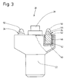
- a light signal 20 according to the invention for signaling acute emergency situations at sea has, in order to be buoyant, a floating body 22.
- the floating body 22 may be formed differently, as the alternative embodiments as a distress night light in Fig. 1 or as a distress signal in Fig. 2 demonstrate.
- the floating body 22 is formed as a hollow body with a single cavity or more cavities and thereby buoyant in the water.
- the float 22 may also be formed of buoyant materials, for example foam plastic.
- An independent orientation of the float 22 in a preferred position in the water 30 can be achieved by a suitable design and, where appropriate, a targeted use of weights, so that at least one upper end portion of the float 22 is above the water surface 32, and the float 22 even with wave movements essentially maintains its upright position.
- one or more light units 24 are arranged in the upper region of the light signal 20.
- the Fig. 1 is the only light unit 24 on the longitudinal central axis 26 of the float 22.
- the buoy 22 are associated with two light units 24, wherein between the two light units 24 on the longitudinal central axis 26 is still a smoke detector 28 is arranged.
- a line 36 attached to the rescue means 34 can furthermore be fastened to the floating body 22 by means of a fastening means 38, such as an eyelet or a hook ( Fig. 1 ).
- a receptacle 40 is formed for each of the light signal 20 associated lighting unit 24, which is sealed against the float 22 so that no liquid can penetrate through the interior of the float 22 through them.
- a screw thread 42 is provided for fastening the light unit 24, which corresponds to a corresponding screw thread 44 of the light unit 24, so that the latter can be inserted into the receptacle 40 and screwed into it.
- a sealing ring 46 is arranged on the light unit 24, which comes when screwing the light unit 24 in the receptacle 40 with this in contact and thereby by positive or ., clamping concerns fulfilled a safety or sealing effect.
- the housing 48 of the lighting unit 24 is divided into several areas.
- An upper dome part 50 preferably projects out of the receptacle 40 of the float 22 and has a substantially hemispherical shape.
- the lower part of the housing 48 is formed by a foot part 52, which is completely within the receptacle 40 when mounted in the receptacle 40 light unit 24. In the upper part of this foot 52, the sealing ring 46 and the screw 44 are arranged.
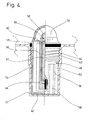
- the housing 48 which is hermetically sealed, is composed of several components. For example, these may be two halves of the housing 48, as in FIG Fig. 4 is shown. An upper half, which includes the dome part 50, and a lower half with a part of the foot part 52 are permanently and tightly connected to each other by a weld 54, for example a friction welding or high-frequency welding.
- a weld 54 for example a friction welding or high-frequency welding.
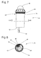
- the lighting unit 24, as shown for example in Fig. 7 is shown, such a connection can be arranged in the form of a weld 54 but also in the region between dome part 50 and foot 52.
- a composition of more than two parts is conceivable, as well as other types of connections, such as gluing or similar, can be used.
- a serving as a light source LED 56 is located in the interior of the dome part 50.
- a serving as a light source LED 56 is located in the interior of the dome part 50.
- the relatively directed light output of the light emitting diode 56 at an angle of typically 100 ° to 140 ° in a solid angle range of at least 180 °, ie a hemispherical region is the light emitting portion of the light emitting diode 56 around a scattering lens 58 arranged.
- the diffuser lens 58 which is made of a transparent or translucent material such as polycarbonate, is able to scatter the light emitted by the light emitting diode 56 substantially homogeneously at least in all directions of the hemispherical portion of the dome portion 50.
- the scattering lens 58 has a lens body 84 which is made of transparent, clear material, in this case made of polycarbonate. In the interior of this lens body 84, a cavity 86 is recessed, in which the light-emitting diode 56 can be used. The cavity 86 has a parabolic shape in section. The outer contour 88 of the lens body 84, however, has a serrated appearance in longitudinal section. Since the scattering lens 58 is constructed substantially rotationally symmetrical with respect to its longitudinal center axis 90, a construction of the lens body 84 accordingly results according to type a Fresnel lens, such as in the Fig. 11 and 12 can be seen. On the outer circumference of the scattering lens 58 circumferential, prism-like formations are arranged.
- the light-emitting diode 56 is arranged on a horizontally arranged circuit board 60, which is connected to a vertical circuit board 62, on which a battery 64 and a reed contact 66 are attached.
- the light-emitting diode 56, the battery 64 and the reed contact 66 are so electrically connected by means of conductors or wires that the light emitting diode 56 is supplied with the reed contact 66 of the battery 64 with electric current.
- the reed contact 66 can be switched on by a magnet 70 movably arranged in a tube 68 when the magnet 70 is located in the vicinity of the reed contact 66.
- the tube 68 is filled with a damping fluid 72 for damping rapid movements of the magnet 70. In order to prevent leakage of the damping fluid 72 and at the same time penetration of gases or liquids, the tube 68 is sealed at its open end with a plug 74.
- a first embodiment of the lighting unit 24 according to the invention is in the Fig. 4 to Fig. 6 described in more detail below.
- two externally accessible recesses 76 and 78 are formed in the housing 48, the opening of which is located in the bottom region of the foot part 52 of the housing 48.
- the tube 68 is in each case completely usable.
- the recesses 76 and 78 are dense, so that through this no water can get into the float 22.
- the recess 76 is located near the reed contact 66 so that when the magnet 70 is at an end of the tube 68 closest to the reed contact 66, it can turn on and when the magnet 70 is at the other end of the tube 68 is located, the reed contact 66 is not switched on. If the tube 68 is arranged with the magnet 70 in the second recess 78, the magnet 70 is in any possible position within the tube 68 to far from the reed contact 66, so that the magnet 70 can not turn on the latter even when the light signal 20 is in the floating position. Thus, a simple and effective safeguard against unintentional switching on, as is necessary, for example, for transport and storage purposes, by repositioning the tube 68.
- the magnet 70 Due to the downward force of gravity, the magnet 70 is located in the lower region of the tube 68, as can be seen in the figures. In this position, the magnet 70 is closest to the reed contact 66 so that it can turn on. If now the lighting unit 24 together with the tube 68, for example rotated by more than 90 °, for example rotated by 180 ° upside down, the magnet 70 moves by gravity to the opposite end of the tube 68 and thus moves away from the reed contact 66th so that the magnet 70 can not turn it on due to the greater distance to the reed contact 66. An overhead storage of the light unit 24, even if it is mounted in the float 22, thus ensures a shutdown of the light unit 24.
- the float 22 rotates in his substantially upright position.
- the light unit 24 is also in the depicted upright position so that the magnet 70 moves to the lower end of the tube 68 and, as described above, turns on the reed contact 66 to activate the light emitting diode 56.
- FIG. 7 to 11 An alternative embodiment of the invention show the Fig. 7 to 11 , in these, the tube 68 with the magnet 70 is fixedly arranged in the interior of the housing 48 of the light unit 24, so that here too the magnet 70 can switch on the reed contact 66 at one end of the tube 68 and the light-emitting diode 56 is switched off at the other end of the tube 68 becomes.
- an externally accessible, but sealed pin receptacle 80 is formed in the housing 48, in which a locking pin 82 can be used in this embodiment.
- This locking pin 82 is located within the pin receptacle 80 between the reed contact 66 and tube 68, so that the locking pin 82, which is made of magnetic material, the magnetic field of the magnet 70 against the reed contact 66 shields, so that the magnet 70 now in no position within of the tube 68 can turn on the reed contact 66.
- the locking pin 82 which is inserted into the pin receptacle 80 projects beyond the edge of the housing 48, so that it can be easily removed for a and by appropriate design of the corresponding receptacle 40 in the float 22 insertion of the light unit 24 in the recording 40 prevented.
- the locking pin 82 must first be removed prior to installation of the light unit 24 in the float 22 to bring the light unit 24 in an activatable state.
- the invention described above is not limited to the embodiments shown, so that other embodiments are conceivable.
- the light unit 24 can be used for any differently designed float 22.
Landscapes
- Engineering & Computer Science (AREA)
- Mechanical Engineering (AREA)
- Ocean & Marine Engineering (AREA)
- Arrangement Of Elements, Cooling, Sealing, Or The Like Of Lighting Devices (AREA)
- Audible And Visible Signals (AREA)
Applications Claiming Priority (1)
| Application Number | Priority Date | Filing Date | Title |
|---|---|---|---|
| DE202006018960U DE202006018960U1 (de) | 2006-12-15 | 2006-12-15 | Leuchteinheit für Seenot-Nachtlichter |
Publications (2)
| Publication Number | Publication Date |
|---|---|
| EP1932756A2 true EP1932756A2 (fr) | 2008-06-18 |
| EP1932756A3 EP1932756A3 (fr) | 2013-01-02 |
Family
ID=38989916
Family Applications (1)
| Application Number | Title | Priority Date | Filing Date |
|---|---|---|---|
| EP07024059A Withdrawn EP1932756A3 (fr) | 2006-12-15 | 2007-12-12 | Signal lumineux, en particulier signal lumineux de détresse ou veilleuse de détresse et unité d'éclairage pour un signal d'éclairage |
Country Status (3)
| Country | Link |
|---|---|
| US (1) | US7859425B2 (fr) |
| EP (1) | EP1932756A3 (fr) |
| DE (1) | DE202006018960U1 (fr) |
Cited By (2)
| Publication number | Priority date | Publication date | Assignee | Title |
|---|---|---|---|---|
| DE102011012797A1 (de) * | 2011-03-02 | 2012-09-06 | Seliger und Blümel GbR (vertretungsberechtigter Gesellschafter: Herbert Blümel, 21035 Hamburg) | Rettungsring mit integrierter Signalbeleuchtung |
| DE202013001652U1 (de) | 2013-02-21 | 2013-03-08 | Pyropol Gmbh | Seenotsignaleinrichtung |
Families Citing this family (10)
| Publication number | Priority date | Publication date | Assignee | Title |
|---|---|---|---|---|
| US20100254251A1 (en) * | 2009-04-01 | 2010-10-07 | Moser Baer India Limited | Articles involving encapsulation of hygroscopic materials |
| ITGE20090061A1 (it) * | 2009-08-04 | 2009-11-03 | Nuova Rade S P A | Boa luminosa di segnalazione provvista di dispositivo di accensione/spegnimento |
| US8441360B2 (en) | 2009-09-04 | 2013-05-14 | Raytheon Company | Search and rescue using ultraviolet radiation |
| US8253576B2 (en) * | 2009-09-04 | 2012-08-28 | Raytheon Company | Search and rescue using ultraviolet radiation |
| US8667930B2 (en) * | 2010-09-21 | 2014-03-11 | Raymond T. Hornung | Method and apparatus for averting waterfowl settlements |
| USD784175S1 (en) | 2016-03-07 | 2017-04-18 | Sirius Signal Co. | Floating light signal device and portions thereof |
| US9487279B1 (en) | 2016-05-12 | 2016-11-08 | Richard Sadu Frehm | Signaling apparatus for coupling to an emergency flotation device |
| USD845809S1 (en) * | 2017-07-05 | 2019-04-16 | Timothy Knapp | Buoy |
| USD915650S1 (en) * | 2018-10-02 | 2021-04-06 | Lumitec, Llc | Anchor light |
| USD956602S1 (en) | 2020-03-10 | 2022-07-05 | Sirius Signal, LLC | Visual distress signal device |
Family Cites Families (17)
| Publication number | Priority date | Publication date | Assignee | Title |
|---|---|---|---|---|
| US1669055A (en) * | 1926-08-02 | 1928-05-08 | Hogg Francis | Signal device |
| US2397844A (en) * | 1942-10-01 | 1946-04-02 | Rca Corp | Signaling apparatus |
| US2642591A (en) * | 1951-05-24 | 1953-06-23 | Clyde R Craver | Life preserver and illuminating means therefor |
| DE1678173U (de) * | 1954-03-08 | 1954-06-16 | Pyrowerk Carl Flemming | Elektro-rettungsbojenlicht. |
| JPS4933478B1 (fr) * | 1968-09-03 | 1974-09-06 | ||
| US3818428A (en) * | 1970-06-15 | 1974-06-18 | A Phipps | Safety light |
| US3833955A (en) * | 1971-04-21 | 1974-09-10 | C Hulbert | Multipurpose light assembly |
| FR2495099A1 (fr) * | 1980-12-01 | 1982-06-04 | Vancheri Patrice | Balise de securite pour plongeurs |
| US4669990A (en) * | 1984-07-30 | 1987-06-02 | Mcdermott Kevin | Signal device |
| US4736205A (en) * | 1986-06-11 | 1988-04-05 | Automatic Power, Inc. | Buoy lantern assembly employing hinged gimbal |
| GB2196906B (en) * | 1986-11-04 | 1991-04-03 | Seacater Overseas Limited | Method and apparatus for locating an object |
| EP0283781B1 (fr) * | 1987-03-10 | 1993-01-20 | Kabushiki Kaisha Toshiba | Dispositif de commutation |
| US4896620A (en) * | 1989-02-01 | 1990-01-30 | Jones Harry E | Marine buoy |
| US5029293A (en) * | 1990-01-30 | 1991-07-02 | Pierre Fontanille | Device for locating an individual fallen into the sea |
| US5520486A (en) * | 1994-09-09 | 1996-05-28 | Van Wyck; William | Diver safety apparatus and method |
| US5800044A (en) * | 1996-12-10 | 1998-09-01 | Marshall; Richard S. | Combination man overboard personal rescue light |
| JP2000062687A (ja) * | 1998-08-25 | 2000-02-29 | Matsuyoshi Kikuchi | 救命用ライト |
-
2006
- 2006-12-15 DE DE202006018960U patent/DE202006018960U1/de not_active Expired - Lifetime
-
2007
- 2007-12-12 EP EP07024059A patent/EP1932756A3/fr not_active Withdrawn
- 2007-12-14 US US11/956,739 patent/US7859425B2/en not_active Expired - Fee Related
Non-Patent Citations (1)
| Title |
|---|
| None |
Cited By (2)
| Publication number | Priority date | Publication date | Assignee | Title |
|---|---|---|---|---|
| DE102011012797A1 (de) * | 2011-03-02 | 2012-09-06 | Seliger und Blümel GbR (vertretungsberechtigter Gesellschafter: Herbert Blümel, 21035 Hamburg) | Rettungsring mit integrierter Signalbeleuchtung |
| DE202013001652U1 (de) | 2013-02-21 | 2013-03-08 | Pyropol Gmbh | Seenotsignaleinrichtung |
Also Published As
| Publication number | Publication date |
|---|---|
| EP1932756A3 (fr) | 2013-01-02 |
| DE202006018960U1 (de) | 2008-01-31 |
| US20080150764A1 (en) | 2008-06-26 |
| US7859425B2 (en) | 2010-12-28 |
Similar Documents
| Publication | Publication Date | Title |
|---|---|---|
| EP1932756A2 (fr) | Signal lumineux, en particulier signal lumineux de détresse ou veilleuse de détresse et unité d'éclairage pour un signal d'éclairage | |
| DE69513654T2 (de) | Unterwasserleuchte | |
| DE69123441T2 (de) | Notfall-hinweisgerät | |
| EP1156272B1 (fr) | Source lumineuse | |
| EP1615185A1 (fr) | Dispositif de balisage pour aéronef monté sur des eoliennes | |
| DE102009006420A1 (de) | LED-Lampe, Fassung und Verfahren zum Betreiben einer LED-Lampe | |
| DE2853018A1 (de) | Angelrutenhalter mit signaleinrichtung | |
| EP2581335B1 (fr) | Winch avec éclairage | |
| DE8902670U1 (de) | Unterhaltungsvorrichtung in Form eines Spielzeugblinklichtes | |
| AT516060B1 (de) | Beleuchtungs- und Sicherheitsvorrichtung für Schiffe | |
| EP1371896A2 (fr) | Lampe pour plongeurs | |
| DE202004012513U1 (de) | Weiße Lampenbaueinheit, die eine LED als Lichtquelle verwendet | |
| DE20003533U1 (de) | Trinkgefäß | |
| EP1647762A2 (fr) | Lampe halogène rechargeable à diodes électroluminescentes et lumière fluorescente | |
| DE202007016896U1 (de) | Rettungsbojenlicht | |
| WO2019105507A1 (fr) | Ensemble serrure de véhicule automobile | |
| DE9209490U1 (de) | Beleuchtungseinrichtung für ein Blumenaquarium | |
| DE69426557T2 (de) | Lampe und Lampenanordnung mit lösbarer Verbindung mit einer rohrförmigen Struktur | |
| DE60311242T2 (de) | Signalvorrichtung für Sichtortungssystem, z.B. für Rettungsfahrzeug in Schiffahrtkunde und ähnliche Bereiche | |
| DE4322605C2 (de) | Gefahrwarneinrichtung für Taxenfahrzeuge | |
| DE202020106816U1 (de) | Tauchlicht | |
| DE9419593U1 (de) | Unterwasserlampe | |
| DE29508949U1 (de) | Flaschen-Verschlußeinrichtung mit einem Ziergegenstand | |
| DE20000069U1 (de) | Taschenlampe | |
| DE10211784A1 (de) | Energie-Spar-Navigationslichter |
Legal Events
| Date | Code | Title | Description |
|---|---|---|---|
| PUAI | Public reference made under article 153(3) epc to a published international application that has entered the european phase |
Free format text: ORIGINAL CODE: 0009012 |
|
| AK | Designated contracting states |
Kind code of ref document: A2 Designated state(s): AT BE BG CH CY CZ DE DK EE ES FI FR GB GR HU IE IS IT LI LT LU LV MC MT NL PL PT RO SE SI SK TR |
|
| AX | Request for extension of the european patent |
Extension state: AL BA HR MK RS |
|
| RAP1 | Party data changed (applicant data changed or rights of an application transferred) |
Owner name: CHEMRING MARINE GERMANY GMBH |
|
| PUAL | Search report despatched |
Free format text: ORIGINAL CODE: 0009013 |
|
| AK | Designated contracting states |
Kind code of ref document: A3 Designated state(s): AT BE BG CH CY CZ DE DK EE ES FI FR GB GR HU IE IS IT LI LT LU LV MC MT NL PL PT RO SE SI SK TR |
|
| AX | Request for extension of the european patent |
Extension state: AL BA HR MK RS |
|
| RIC1 | Information provided on ipc code assigned before grant |
Ipc: B63C 9/20 20060101ALI20121127BHEP Ipc: B63C 9/00 20060101AFI20121127BHEP |
|
| AKY | No designation fees paid | ||
| STAA | Information on the status of an ep patent application or granted ep patent |
Free format text: STATUS: THE APPLICATION IS DEEMED TO BE WITHDRAWN |
|
| 18D | Application deemed to be withdrawn |
Effective date: 20130703 |