EP1932801A1 - Eingebaute Arretiereinrichtung - Google Patents
Eingebaute Arretiereinrichtung Download PDFInfo
- Publication number
- EP1932801A1 EP1932801A1 EP07024401A EP07024401A EP1932801A1 EP 1932801 A1 EP1932801 A1 EP 1932801A1 EP 07024401 A EP07024401 A EP 07024401A EP 07024401 A EP07024401 A EP 07024401A EP 1932801 A1 EP1932801 A1 EP 1932801A1
- Authority
- EP
- European Patent Office
- Prior art keywords
- chamber
- assembly
- housing part
- inlet
- spigot
- Prior art date
- Legal status (The legal status is an assumption and is not a legal conclusion. Google has not performed a legal analysis and makes no representation as to the accuracy of the status listed.)
- Granted
Links
- 239000007788 liquid Substances 0.000 claims description 22
- 239000013049 sediment Substances 0.000 claims description 11
- 238000003780 insertion Methods 0.000 claims description 7
- 230000037431 insertion Effects 0.000 claims description 7
- 238000000034 method Methods 0.000 claims description 6
- 238000007789 sealing Methods 0.000 claims description 4
- 238000000465 moulding Methods 0.000 description 10
- 235000014101 wine Nutrition 0.000 description 7
- 230000000712 assembly Effects 0.000 description 3
- 238000000429 assembly Methods 0.000 description 3
- 235000013405 beer Nutrition 0.000 description 3
- 238000007254 oxidation reaction Methods 0.000 description 3
- 240000004808 Saccharomyces cerevisiae Species 0.000 description 2
- 238000000855 fermentation Methods 0.000 description 2
- 230000004151 fermentation Effects 0.000 description 2
- 235000019985 fermented beverage Nutrition 0.000 description 2
- 230000003647 oxidation Effects 0.000 description 2
- 239000002244 precipitate Substances 0.000 description 2
- 208000034656 Contusions Diseases 0.000 description 1
- 241000219094 Vitaceae Species 0.000 description 1
- 230000003213 activating effect Effects 0.000 description 1
- 229910000278 bentonite Inorganic materials 0.000 description 1
- 239000000440 bentonite Substances 0.000 description 1
- SVPXDRXYRYOSEX-UHFFFAOYSA-N bentoquatam Chemical compound O.O=[Si]=O.O=[Al]O[Al]=O SVPXDRXYRYOSEX-UHFFFAOYSA-N 0.000 description 1
- 230000006835 compression Effects 0.000 description 1
- 238000007906 compression Methods 0.000 description 1
- 239000012141 concentrate Substances 0.000 description 1
- 238000011109 contamination Methods 0.000 description 1
- 239000006025 fining agent Substances 0.000 description 1
- 239000012530 fluid Substances 0.000 description 1
- 235000019674 grape juice Nutrition 0.000 description 1
- 235000021021 grapes Nutrition 0.000 description 1
- 238000002347 injection Methods 0.000 description 1
- 239000007924 injection Substances 0.000 description 1
- 239000002245 particle Substances 0.000 description 1
- 238000010079 rubber tapping Methods 0.000 description 1
- 239000000126 substance Substances 0.000 description 1
- 238000011514 vinification Methods 0.000 description 1
Images



Classifications
-
- B—PERFORMING OPERATIONS; TRANSPORTING
- B67—OPENING, CLOSING OR CLEANING BOTTLES, JARS OR SIMILAR CONTAINERS; LIQUID HANDLING
- B67D—DISPENSING, DELIVERING OR TRANSFERRING LIQUIDS, NOT OTHERWISE PROVIDED FOR
- B67D3/00—Apparatus or devices for controlling flow of liquids under gravity from storage containers for dispensing purposes
- B67D3/04—Liquid-dispensing taps or cocks adapted to seal and open tapping holes of casks, e.g. for beer
- B67D3/047—Liquid-dispensing taps or cocks adapted to seal and open tapping holes of casks, e.g. for beer with a closing element having a rotational movement
-
- C—CHEMISTRY; METALLURGY
- C12—BIOCHEMISTRY; BEER; SPIRITS; WINE; VINEGAR; MICROBIOLOGY; ENZYMOLOGY; MUTATION OR GENETIC ENGINEERING
- C12C—BEER; PREPARATION OF BEER BY FERMENTATION; PREPARATION OF MALT FOR MAKING BEER; PREPARATION OF HOPS FOR MAKING BEER
- C12C13/00—Brewing devices, not covered by a single group of C12C1/00 - C12C12/04
- C12C13/10—Home brew equipment
-
- C—CHEMISTRY; METALLURGY
- C12—BIOCHEMISTRY; BEER; SPIRITS; WINE; VINEGAR; MICROBIOLOGY; ENZYMOLOGY; MUTATION OR GENETIC ENGINEERING
- C12G—WINE; PREPARATION THEREOF; ALCOHOLIC BEVERAGES; PREPARATION OF ALCOHOLIC BEVERAGES NOT PROVIDED FOR IN SUBCLASSES C12C OR C12H
- C12G1/00—Preparation of wine or sparkling wine
- C12G1/02—Preparation of must from grapes; Must treatment and fermentation
- C12G1/0206—Preparation of must from grapes; Must treatment and fermentation using a home wine making vessel
Definitions
- the present invention relates generally to spigot assemblies.
- spigot assemblies for emptying containers filled with liquid.
- Some devices arrange for the alignment of two or more holes in a spigot assembly in order to permit liquid to flow from the interior of the vessel to its exterior.
- the liquid fills a chamber of the spigot assembly until the spigot is activated to allow flow from the container. If the spigot assembly is located on the side of the vessel, air bubbles and sediment may then collect within the chamber of the spigot assembly. This may lead to blockage in the spigot assembly, or contamination or oxidation of the liquid.
- the liquid is then typically decanted from the container into a second container where typically a fining agent such as Bentonite is added, and further sediment precipitates out of the liquid.
- a fining agent such as Bentonite
- U.S. Patent No. 1,815,501 Another type of draw-off arrangement for liquid containers is provided in U.S. Patent No. 1,815,501 .
- This patent provides for a separate chamber between a container and a tap. Rotation of the tap into the spigot body uses interacting longitudinal ribs to rotate the spigot into an open position.
- U.S. Patent 3,302,660 which describes a tapping valve for a beer keg.
- the disclosed valve is designed for a pressurized container, and comprises a valve completely inserted into a keg. Is also has an interior valve space into which openings are aligned and uses a surface to surface seal when the opening is in a closed position.
- U.S. Patent No. 4,632,362 Another example of a patent which provides for rotation of a spigot in a sleeve for alignment of outlet holes is provided in U.S. Patent No. 4,632,362 .
- the spigot fits tightly into the body member, but may be rotated to align the outlet holes in two cylindrical portions of the spigot, thereby opening or closing the tap.
- the outer surface of the inner cylindrical portion sealingly fits the inner surface of the outer cylindrical portion to prevent leakage, and is held in place by a ridge and groove design.
- the entire assembly is heat sealed to a container.
- a plug is provided to fit into the outer end of the spigot, allowing the container to be filled through the opening.
- An object of the invention is to provide a spigot assembly for a container which assembly substantially avoids entrapment of either sediment or air in or on the assembly.
- a first spigot assembly In one embodiment of the spigot assembly, there is provided a first spigot assembly, an inner molding and an outer cylinder.
- the first spigot assembly may be injection molded from plastic.
- the first spigot assembly comprises an open ended cylinder having a protruding second hollow cylinder having an open end defining a chamber.
- the spigot assembly also comprises a rotator part capable of insertion into the open ended cylinder and has an inlet capable of communicating with the outlet of the chamber.
- the rotator part is capable of rotating within the open ended cylinder bringing the inlet and outlet into alignment and out of alignment.
- the rotator part also has an outlet, thereby allowing fluid to flow from the outlet in the chamber, into the inlet in the rotator part and out the outlet of the rotator part.
- the inner molding is in the form of a cylinder closed at one end and sized to fit tightly within the chamber.
- the closed end is provided a first small opening, providing the only inlet into the chamber.
- the wall is conFig.d to form a passageway between the first small opening the outlet.
- the outer cylinder comprises a cylinder sized to receive the first spigot assembly, and substantially closed at one end.
- the substantially closed end is provided a second small opening.
- a seal is also provided which surrounds the second small opening.
- Also provided on the interior wall of the cylinder are keyways extending from the open end and ending at a rotation track. These keyways correspond with projections on the exterior wall of the chamber.
- the substantially closed end of the outer cylinder is capable of insertion into a suitable container, such that it is mounted flush with the interior surface of the container and such that no leakage occurs around the outer cylinder.
- the first spigot assembly is made from two separate components, a tap structure, and an inner molding.
- the tap structure comprises an open ended cylinder having a protruding second cylinder part having an open end defining a chamber and an outlet from the closed end of the cylinder communicating with the interior of the open ended cylinder.
- the tap structure also comprises a rotator part capable of insertion into the open ended cylinder and having an inlet capable of communicating with the outlet of the chamber. The rotator part is capable of rotating within the open ended cylinder bringing the inlet and outlet into alignment and out of alignment.
- the inner molding is open at one end, and has a small opening at a closed end.
- the inner molding is capable of insertion into the chamber of the tap assembly so that the small inner molding's closed end partially seals the tap assembly.
- the inner molding and tap assembly may be friction fitted together along keyways provided for this purpose, in either case, the insertion forms a spigot assembly.
- the tap structure is now closed at its outer end by the closed end of the inner molding.
- the first small opening provides the only inlet to the chamber formed by the combination of the tap structure and the inner molding.
- the spigot assembly must then be inserted into the outer cylinder.
- the spigot assembly is inserted into the outer cylinder, so that the first small opening is out of alignment with the second small opening.
- the spigot assembly is rotated so that that the projections in the track locks the spigot assembly into the outer cylinder.
- the seal associated with the second small opening is compressed, preventing any flow or leakage from the interior of the container to the chamber.
- the spigot assembly is rotated until it is in an upright position and the first and second small openings are aligned. This allows the flow of liquid into the chamber.
- the rotator part may be rotated to align its opening with the outlet of the chamber. This allows liquid to flow from the chamber and out the end of the tap assembly.
- FIG. 1 is a front perspective view of a vessel incorporating an embodiment of the present invention.
- FIG. 2 is a vertical cross-section through a side of the tap and associated housing part according to one embodiment of the invention
- FIG. 3 is a vertical cross-section through a side of a further housing part according to the embodiment of Fig. 1 ;
- Fig. 4 is a vertical cross-section through a side of a further housing part according to the embodiment of Fig. 1 ;
- Fig. 5 is a side view of the tap and associated housing part according to the embodiment of Fig. 1 ;
- Fig. 6 is a rear view of the housing part according to Fig. 1 ;
- Fig. 7 is a front view of the housing part according to Fig. 3 ;
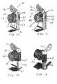
- Fig. 8 is a schematic end view of the assembled spigot assembly according to Fig. 2 to 4 , illustrating the stages in assembling and activating the assembly;
- Fig. 9 is a vertical cross-section through the assembled spigot assembly
- Fig. 10 is a cutaway perspective view of the tap assembly and an associated housing part
- Fig. 11 is a cutaway perspective view of the top assembly and a further housing part
- Fig. 12 is a perspective rear view of the partially assembled spigot assembly of Fig. 11 ;
- Fig. 13 is a perspective front view of the partially assembled spigot assembly of Fig. 11 ;
- Fig. 14 is a front view of a partially assembled tap assembly, where the further housing part is affixed to a container.
- Fig. 1 illustrates one contemplated use of the present invention.
- a wine making vessel 2 with an outer container 4 that incorporates an embodiment of a spigot assembly 8 according to the present invention.
- the assembly 8 is shown in the vessel 2, this is but one contemplated area of use and it is not meant to limit the application of the present invention.
- the spigot assembly 8 comprises a tap assembly 10; a first housing part comprising cylindrical parts 11 and 14; and a second housing part comprising cylindrical part 22.
- the tap assembly 10 is conventional, comprising an open-ended cylinder 48 carrying a tap 46 including a cylindrical barrel 52 open at the end 61. There may also be provided drainage means to drain any unwanted liquid form the barrel 52.
- the barrel 52 is frictionally engaged in cylinder 48 in a sealing engagement.
- Cylinder 48 includes an opening 54 leading via flow path 55 to cylindrical part 11.
- a corresponding opening 50 is provided in barrel 52, so that when the tap 46 is rotated, the opening 50 can be moved into or out of alignment with the opening 54 in the cylinder 48 and hence the cylindrical housing part 11.
- the cylindrical housing part 14 may be frictionally fitted into cylindrical housing part 11, such that end 13 of part 11 mates the wall 20 of part 14 and end 16 of part 14 mates the wall 17 of part 11.
- This frictional fitting is normally intended to be a permanent joining.
- cylindrical housing parts 11 and 14 could comprise a single cylindrical part.
- the housing has been broken into two parts 11 and 14 which are then frictionally fitted together.
- a closed chamber 12 is formed having an inlet opening 18 through housing part 14 and an outlet 55, as described, into tap assembly 10.
- the frictional joining of the two parts may also include a keyway arrangement as, for example, tongue and groove, to positively mechanically prevent relative rotation of the parts once assembled.
- Housing part 11 is provided with at least one but preferably three protrusions 32 on the outside 34 of part 11.
- Cylindrical housing part 22 comprises an open-ended cylinder which includes a keyway 36 corresponding to each protrusion 32 and a guideway 40 which may comprise a groove extending circumferentially about the interior of housing part 22.
- the keyways 36 terminate at guideway 40.
- Housing part 22 also includes an opening 26 in the otherwise closed end thereof. Opening 26 includes a seat for a seal 30, shown as a sealing ring. Seal 30 is typically flattened on the side thereof facing into the cylinder. Another configuration of the seal 30 may be hemispherical, with a central aperture.
- the tap assembly 10 and the chamber assembly can be inserted into housing part 22.
- protrusions 32 are provided on part 11. It is noted from Fig. 6 that the protrusions are unevenly spaced about cylindrical part 11 at annular distances of 105°, 120° and 135°.
- the cooperating keyways 36 are similarly offset to receive the protrusions. It will be noted that the part 14 may be fully inserted into part 11, so that there is a positive engagement between the end edge 15 of part 14 and the end wall 17 of part 11.
- the tap assembly including now joined parts 11 and 14 is turned upside down, shown in Fig. 5 and 6 , and inserted into part 22 with the protrusions 32 keying into keyways 36.
- the tap assembly may be rotated with the protrusions 32 moving along the groove 40.
- Fig. 8 that when the tap assembly is upside down as in Fig. 5 , the opening 18 in part 14 will be in the position 1 shown in discontinuous lines in Fig. 8 . In that position the protrusions 32 have been inserted into the keyways 36 but have not been rotated in the guideway 40.
- the tap assembly is then rotated 90° in the guideway 40. At this stage the tap assembly is locked into the part 22, because the protrusions 32 have been rotated out alignment with the keyways 36.
- the opening 18 of part 14 is in the position shown in discontinuous lines as position 2 in Fig. 8 .
- the opening 18 remains out of alignment with the opening 26, so that the compressive force remains on the seal.
- the opening 18 is then in position 3 in Fig. 8 ; that is, in alignment with opening 26. At that point liquid can flow into chamber 12. Outflow from chamber 12 is then controlled by tap 46.
- the part 22 is preferably first secured in a suitable opening in the side of a container 4, such that the end surface 28 of part 22 is flush with the interior wall of the container 4.
- the interior wall of the container 4 and the part 22 thus present a substantially smooth continuous internal surface in the container.
- the flush mounting thus does not present any protruding surface upon which sediment might collect and subsequently be drawn into the chamber 12 when the tap assembly is rotated to put opening 18 in alignment with opening 26.
- a shallow space may of necessity be left on the surface 28 of the end wall of part 22.
- the steeply sloping edge 44 of that space strongly mitigates against any sediment being trapped in that space.
- a channel 68 is formed within chamber 12 by a top wall 63 and a pair of side walls 64. Only one of side walls 64 is shown in the cutaway of Fig. 11 .
- a second chamber 65 is thus also formed.
- the fermentation vessel may be suitable to brew any fermented liquid for consumption, including but not limited to beer, wine or other spirit.
- the invention has a scope which is commensurate with the claims of this patent specification including any elements or aspects which would be seen to be equivalent to those set out in the accompanying claims.
Landscapes
- Engineering & Computer Science (AREA)
- Organic Chemistry (AREA)
- Chemical & Material Sciences (AREA)
- Genetics & Genomics (AREA)
- Wood Science & Technology (AREA)
- Bioinformatics & Cheminformatics (AREA)
- General Engineering & Computer Science (AREA)
- General Health & Medical Sciences (AREA)
- Health & Medical Sciences (AREA)
- Life Sciences & Earth Sciences (AREA)
- Biochemistry (AREA)
- Zoology (AREA)
- Food Science & Technology (AREA)
- Mechanical Engineering (AREA)
- Devices For Dispensing Beverages (AREA)
- Joints With Sleeves (AREA)
- Lock And Its Accessories (AREA)
Applications Claiming Priority (1)
| Application Number | Priority Date | Filing Date | Title |
|---|---|---|---|
| US87518106P | 2006-12-15 | 2006-12-15 |
Publications (2)
| Publication Number | Publication Date |
|---|---|
| EP1932801A1 true EP1932801A1 (de) | 2008-06-18 |
| EP1932801B1 EP1932801B1 (de) | 2010-09-22 |
Family
ID=39202061
Family Applications (1)
| Application Number | Title | Priority Date | Filing Date |
|---|---|---|---|
| EP07024401A Not-in-force EP1932801B1 (de) | 2006-12-15 | 2007-12-17 | Eingebaute Arretiereinrichtung |
Country Status (5)
| Country | Link |
|---|---|
| US (1) | US7837072B2 (de) |
| EP (1) | EP1932801B1 (de) |
| AT (1) | ATE482170T1 (de) |
| CA (1) | CA2615155A1 (de) |
| DE (1) | DE602007009350D1 (de) |
Families Citing this family (4)
| Publication number | Priority date | Publication date | Assignee | Title |
|---|---|---|---|---|
| JP4292442B2 (ja) | 2000-01-31 | 2009-07-08 | ソニー株式会社 | 全地球測位システムの受信装置及び携帯無線端末 |
| US20150343470A1 (en) * | 2010-01-28 | 2015-12-03 | Sun Solutions Ltd. | Spray mineral water bottle and cap of spray mineral water bottle |
| GB201820596D0 (en) * | 2018-12-18 | 2019-01-30 | Salts Healthcare Ltd | A valve for a urostomy appliance |
| US20220386643A1 (en) * | 2019-10-29 | 2022-12-08 | Fuji Oil Holdings Inc. | Cocoa substitute |
Citations (6)
| Publication number | Priority date | Publication date | Assignee | Title |
|---|---|---|---|---|
| US1381598A (en) | 1920-02-17 | 1921-06-14 | August C Stoll | Spigot |
| US1815501A (en) | 1929-02-09 | 1931-07-21 | Francis Henry | Draw off arrangement for liquid containers |
| US3302660A (en) | 1966-04-22 | 1967-02-07 | Baron F Haag | Tapping valve for beer keg |
| US4632362A (en) | 1983-02-16 | 1986-12-30 | Waddington & Duval Limited | Tap |
| EP0246052A1 (de) * | 1986-05-10 | 1987-11-19 | Cadbury Schweppes Limited | Getränkespender |
| WO2003074979A1 (en) | 2002-03-04 | 2003-09-12 | Molly Polly Innovations Pty Ltd | Metering tap |
Family Cites Families (14)
| Publication number | Priority date | Publication date | Assignee | Title |
|---|---|---|---|---|
| US675548A (en) * | 1900-12-05 | 1901-06-04 | Irwin F Long | Faucet. |
| US1859126A (en) * | 1929-03-25 | 1932-05-17 | Boeuf Pierre Eugene | Cock |
| BE371486A (de) * | 1929-08-16 | |||
| US3308224A (en) * | 1963-06-17 | 1967-03-07 | Waddington & Duval Holding Ltd | Method of producing spigot taps |
| US4200123A (en) * | 1978-10-10 | 1980-04-29 | Brandelli Anthony R | Ball-type faucet |
| DK163583A (da) * | 1982-04-30 | 1983-10-31 | Diemoulders Pty Ltd | Aftapningshane |
| US4621750A (en) * | 1985-04-12 | 1986-11-11 | The Meyer Company | Dispenser valve |
| US4997108A (en) * | 1988-07-04 | 1991-03-05 | Hideaki Hata | Tap and liquid dispenser using the same |
| CA2094410C (en) * | 1992-06-18 | 1998-05-05 | Joshua Seth Auerbach | Distributed management communications network |
| US5574934A (en) * | 1993-11-24 | 1996-11-12 | Intel Corporation | Preemptive priority-based transmission of signals using virtual channels |
| US6101180A (en) * | 1996-11-12 | 2000-08-08 | Starguide Digital Networks, Inc. | High bandwidth broadcast system having localized multicast access to broadcast content |
| US6154463A (en) * | 1997-08-26 | 2000-11-28 | Lucent Technologies, Inc. | System and method for multicast conferencing and online discussion groups |
| US6826612B1 (en) * | 1999-12-21 | 2004-11-30 | Alcatel Canada Inc. | Method and apparatus for an improved internet group management protocol |
| CA119528S (en) * | 2007-02-19 | 2008-09-16 | Vineco Internat Products Ltd | Wine making vessel |
-
2007
- 2007-12-17 DE DE602007009350T patent/DE602007009350D1/de active Active
- 2007-12-17 AT AT07024401T patent/ATE482170T1/de not_active IP Right Cessation
- 2007-12-17 CA CA002615155A patent/CA2615155A1/en not_active Abandoned
- 2007-12-17 EP EP07024401A patent/EP1932801B1/de not_active Not-in-force
- 2007-12-17 US US11/957,874 patent/US7837072B2/en not_active Expired - Fee Related
Patent Citations (6)
| Publication number | Priority date | Publication date | Assignee | Title |
|---|---|---|---|---|
| US1381598A (en) | 1920-02-17 | 1921-06-14 | August C Stoll | Spigot |
| US1815501A (en) | 1929-02-09 | 1931-07-21 | Francis Henry | Draw off arrangement for liquid containers |
| US3302660A (en) | 1966-04-22 | 1967-02-07 | Baron F Haag | Tapping valve for beer keg |
| US4632362A (en) | 1983-02-16 | 1986-12-30 | Waddington & Duval Limited | Tap |
| EP0246052A1 (de) * | 1986-05-10 | 1987-11-19 | Cadbury Schweppes Limited | Getränkespender |
| WO2003074979A1 (en) | 2002-03-04 | 2003-09-12 | Molly Polly Innovations Pty Ltd | Metering tap |
Also Published As
| Publication number | Publication date |
|---|---|
| EP1932801B1 (de) | 2010-09-22 |
| CA2615155A1 (en) | 2008-06-15 |
| US7837072B2 (en) | 2010-11-23 |
| US20090001105A1 (en) | 2009-01-01 |
| ATE482170T1 (de) | 2010-10-15 |
| DE602007009350D1 (de) | 2010-11-04 |
Similar Documents
| Publication | Publication Date | Title |
|---|---|---|
| US5511692A (en) | Fluid dispense system | |
| EP2632844B1 (de) | Ausgabevorrichtung mit entfernbarer ausgabekartusche | |
| US8640931B2 (en) | Tri-function tap for beverages | |
| EP1324943B1 (de) | Flüssigkeitsabgabeverschlusselement | |
| US8596478B2 (en) | Cap assembly with attached flexible liner for use with a container to hold contents therein | |
| RU2286931C2 (ru) | Сливной затвор для емкостей, содержащих текучий продукт | |
| US7837072B2 (en) | Flush mounted spigot assembly | |
| DK2928814T3 (en) | BEVERAGE DRAFT AND CONTAINER FOR USE IN A BEVERAGE DRAFT | |
| US20120001112A1 (en) | Apparatus and method for extraction or addition of substances from or to a body of liquid | |
| CN113165859B (zh) | 用于通过包括分配阀的分配管来分配饮料的套件 | |
| EP4481308A1 (de) | Kühlgerät | |
| WO2007027654A3 (en) | Apparatus and methods for multi-fluid dispensing systems | |
| KR200348302Y1 (ko) | 위조방지용 병뚜껑 | |
| US3880182A (en) | Universal valve system for beer kegs and the like | |
| CN220339746U (zh) | 一种圆柱型球阀液体取样器 | |
| KR200363544Y1 (ko) | 위조방지용 병뚜껑 | |
| KR100649479B1 (ko) | 용기 마개 | |
| CN221069225U (zh) | 一种液体抽取装置组件及有机液体容纳桶 | |
| CN221139299U (zh) | 一种灌装用的多重防菌阀口及具有其的快配系统无菌袋 | |
| CN220411412U (zh) | 一种分体盖 | |
| KR102873025B1 (ko) | 음료 혼합 용기 | |
| JPH1179290A (ja) | 炭酸飲料注出方法および炭酸飲料注出装置 | |
| CN216003701U (zh) | 瓶盖及具有其的饮料瓶 | |
| KR20040039555A (ko) | 음료용기 개폐장치 | |
| KR20230135464A (ko) | 탄산 유지를 위한 마개 시스템 |
Legal Events
| Date | Code | Title | Description |
|---|---|---|---|
| PUAI | Public reference made under article 153(3) epc to a published international application that has entered the european phase |
Free format text: ORIGINAL CODE: 0009012 |
|
| AK | Designated contracting states |
Kind code of ref document: A1 Designated state(s): AT BE BG CH CY CZ DE DK EE ES FI FR GB GR HU IE IS IT LI LT LU LV MC MT NL PL PT RO SE SI SK TR |
|
| AX | Request for extension of the european patent |
Extension state: AL BA HR MK RS |
|
| 17P | Request for examination filed |
Effective date: 20081110 |
|
| 17Q | First examination report despatched |
Effective date: 20090122 |
|
| AKX | Designation fees paid |
Designated state(s): AT BE BG CH CY CZ DE DK EE ES FI FR GB GR HU IE IS IT LI LT LU LV MC MT NL PL PT RO SE SI SK TR |
|
| RAP1 | Party data changed (applicant data changed or rights of an application transferred) |
Owner name: GLOBAL VINTNERS INC. / VITICULTEURS GLOBAL INC. |
|
| GRAP | Despatch of communication of intention to grant a patent |
Free format text: ORIGINAL CODE: EPIDOSNIGR1 |
|
| GRAS | Grant fee paid |
Free format text: ORIGINAL CODE: EPIDOSNIGR3 |
|
| GRAA | (expected) grant |
Free format text: ORIGINAL CODE: 0009210 |
|
| AK | Designated contracting states |
Kind code of ref document: B1 Designated state(s): AT BE BG CH CY CZ DE DK EE ES FI FR GB GR HU IE IS IT LI LT LU LV MC MT NL PL PT RO SE SI SK TR |
|
| REG | Reference to a national code |
Ref country code: GB Ref legal event code: FG4D |
|
| REG | Reference to a national code |
Ref country code: CH Ref legal event code: EP |
|
| REG | Reference to a national code |
Ref country code: IE Ref legal event code: FG4D |
|
| REF | Corresponds to: |
Ref document number: 602007009350 Country of ref document: DE Date of ref document: 20101104 Kind code of ref document: P |
|
| PG25 | Lapsed in a contracting state [announced via postgrant information from national office to epo] |
Ref country code: AT Free format text: LAPSE BECAUSE OF FAILURE TO SUBMIT A TRANSLATION OF THE DESCRIPTION OR TO PAY THE FEE WITHIN THE PRESCRIBED TIME-LIMIT Effective date: 20100922 Ref country code: FI Free format text: LAPSE BECAUSE OF FAILURE TO SUBMIT A TRANSLATION OF THE DESCRIPTION OR TO PAY THE FEE WITHIN THE PRESCRIBED TIME-LIMIT Effective date: 20100922 Ref country code: LT Free format text: LAPSE BECAUSE OF FAILURE TO SUBMIT A TRANSLATION OF THE DESCRIPTION OR TO PAY THE FEE WITHIN THE PRESCRIBED TIME-LIMIT Effective date: 20100922 |
|
| REG | Reference to a national code |
Ref country code: NL Ref legal event code: VDEP Effective date: 20100922 |
|
| LTIE | Lt: invalidation of european patent or patent extension |
Effective date: 20100922 |
|
| PG25 | Lapsed in a contracting state [announced via postgrant information from national office to epo] |
Ref country code: PL Free format text: LAPSE BECAUSE OF FAILURE TO SUBMIT A TRANSLATION OF THE DESCRIPTION OR TO PAY THE FEE WITHIN THE PRESCRIBED TIME-LIMIT Effective date: 20100922 Ref country code: SI Free format text: LAPSE BECAUSE OF FAILURE TO SUBMIT A TRANSLATION OF THE DESCRIPTION OR TO PAY THE FEE WITHIN THE PRESCRIBED TIME-LIMIT Effective date: 20100922 |
|
| PG25 | Lapsed in a contracting state [announced via postgrant information from national office to epo] |
Ref country code: LV Free format text: LAPSE BECAUSE OF FAILURE TO SUBMIT A TRANSLATION OF THE DESCRIPTION OR TO PAY THE FEE WITHIN THE PRESCRIBED TIME-LIMIT Effective date: 20100922 Ref country code: SE Free format text: LAPSE BECAUSE OF FAILURE TO SUBMIT A TRANSLATION OF THE DESCRIPTION OR TO PAY THE FEE WITHIN THE PRESCRIBED TIME-LIMIT Effective date: 20100922 Ref country code: GR Free format text: LAPSE BECAUSE OF FAILURE TO SUBMIT A TRANSLATION OF THE DESCRIPTION OR TO PAY THE FEE WITHIN THE PRESCRIBED TIME-LIMIT Effective date: 20101223 |
|
| PG25 | Lapsed in a contracting state [announced via postgrant information from national office to epo] |
Ref country code: CZ Free format text: LAPSE BECAUSE OF FAILURE TO SUBMIT A TRANSLATION OF THE DESCRIPTION OR TO PAY THE FEE WITHIN THE PRESCRIBED TIME-LIMIT Effective date: 20100922 Ref country code: IS Free format text: LAPSE BECAUSE OF FAILURE TO SUBMIT A TRANSLATION OF THE DESCRIPTION OR TO PAY THE FEE WITHIN THE PRESCRIBED TIME-LIMIT Effective date: 20110122 Ref country code: EE Free format text: LAPSE BECAUSE OF FAILURE TO SUBMIT A TRANSLATION OF THE DESCRIPTION OR TO PAY THE FEE WITHIN THE PRESCRIBED TIME-LIMIT Effective date: 20100922 Ref country code: PT Free format text: LAPSE BECAUSE OF FAILURE TO SUBMIT A TRANSLATION OF THE DESCRIPTION OR TO PAY THE FEE WITHIN THE PRESCRIBED TIME-LIMIT Effective date: 20110124 Ref country code: RO Free format text: LAPSE BECAUSE OF FAILURE TO SUBMIT A TRANSLATION OF THE DESCRIPTION OR TO PAY THE FEE WITHIN THE PRESCRIBED TIME-LIMIT Effective date: 20100922 Ref country code: NL Free format text: LAPSE BECAUSE OF FAILURE TO SUBMIT A TRANSLATION OF THE DESCRIPTION OR TO PAY THE FEE WITHIN THE PRESCRIBED TIME-LIMIT Effective date: 20100922 Ref country code: IT Free format text: LAPSE BECAUSE OF FAILURE TO SUBMIT A TRANSLATION OF THE DESCRIPTION OR TO PAY THE FEE WITHIN THE PRESCRIBED TIME-LIMIT Effective date: 20100922 Ref country code: SK Free format text: LAPSE BECAUSE OF FAILURE TO SUBMIT A TRANSLATION OF THE DESCRIPTION OR TO PAY THE FEE WITHIN THE PRESCRIBED TIME-LIMIT Effective date: 20100922 |
|
| PG25 | Lapsed in a contracting state [announced via postgrant information from national office to epo] |
Ref country code: BE Free format text: LAPSE BECAUSE OF FAILURE TO SUBMIT A TRANSLATION OF THE DESCRIPTION OR TO PAY THE FEE WITHIN THE PRESCRIBED TIME-LIMIT Effective date: 20100922 |
|
| PG25 | Lapsed in a contracting state [announced via postgrant information from national office to epo] |
Ref country code: MC Free format text: LAPSE BECAUSE OF NON-PAYMENT OF DUE FEES Effective date: 20101231 Ref country code: ES Free format text: LAPSE BECAUSE OF FAILURE TO SUBMIT A TRANSLATION OF THE DESCRIPTION OR TO PAY THE FEE WITHIN THE PRESCRIBED TIME-LIMIT Effective date: 20110102 |
|
| PLBE | No opposition filed within time limit |
Free format text: ORIGINAL CODE: 0009261 |
|
| STAA | Information on the status of an ep patent application or granted ep patent |
Free format text: STATUS: NO OPPOSITION FILED WITHIN TIME LIMIT |
|
| 26N | No opposition filed |
Effective date: 20110623 |
|
| PG25 | Lapsed in a contracting state [announced via postgrant information from national office to epo] |
Ref country code: DK Free format text: LAPSE BECAUSE OF FAILURE TO SUBMIT A TRANSLATION OF THE DESCRIPTION OR TO PAY THE FEE WITHIN THE PRESCRIBED TIME-LIMIT Effective date: 20100922 |
|
| REG | Reference to a national code |
Ref country code: DE Ref legal event code: R097 Ref document number: 602007009350 Country of ref document: DE Effective date: 20110623 |
|
| PG25 | Lapsed in a contracting state [announced via postgrant information from national office to epo] |
Ref country code: IE Free format text: LAPSE BECAUSE OF NON-PAYMENT OF DUE FEES Effective date: 20101217 |
|
| PG25 | Lapsed in a contracting state [announced via postgrant information from national office to epo] |
Ref country code: MT Free format text: LAPSE BECAUSE OF FAILURE TO SUBMIT A TRANSLATION OF THE DESCRIPTION OR TO PAY THE FEE WITHIN THE PRESCRIBED TIME-LIMIT Effective date: 20100922 |
|
| REG | Reference to a national code |
Ref country code: CH Ref legal event code: PL |
|
| PG25 | Lapsed in a contracting state [announced via postgrant information from national office to epo] |
Ref country code: CY Free format text: LAPSE BECAUSE OF FAILURE TO SUBMIT A TRANSLATION OF THE DESCRIPTION OR TO PAY THE FEE WITHIN THE PRESCRIBED TIME-LIMIT Effective date: 20100922 |
|
| PG25 | Lapsed in a contracting state [announced via postgrant information from national office to epo] |
Ref country code: LU Free format text: LAPSE BECAUSE OF NON-PAYMENT OF DUE FEES Effective date: 20101217 Ref country code: BG Free format text: LAPSE BECAUSE OF FAILURE TO SUBMIT A TRANSLATION OF THE DESCRIPTION OR TO PAY THE FEE WITHIN THE PRESCRIBED TIME-LIMIT Effective date: 20100922 Ref country code: HU Free format text: LAPSE BECAUSE OF FAILURE TO SUBMIT A TRANSLATION OF THE DESCRIPTION OR TO PAY THE FEE WITHIN THE PRESCRIBED TIME-LIMIT Effective date: 20110323 |
|
| PG25 | Lapsed in a contracting state [announced via postgrant information from national office to epo] |
Ref country code: CH Free format text: LAPSE BECAUSE OF NON-PAYMENT OF DUE FEES Effective date: 20111231 Ref country code: LI Free format text: LAPSE BECAUSE OF NON-PAYMENT OF DUE FEES Effective date: 20111231 Ref country code: TR Free format text: LAPSE BECAUSE OF FAILURE TO SUBMIT A TRANSLATION OF THE DESCRIPTION OR TO PAY THE FEE WITHIN THE PRESCRIBED TIME-LIMIT Effective date: 20100922 |
|
| PGFP | Annual fee paid to national office [announced via postgrant information from national office to epo] |
Ref country code: GB Payment date: 20130102 Year of fee payment: 6 Ref country code: DE Payment date: 20130228 Year of fee payment: 6 Ref country code: FR Payment date: 20130124 Year of fee payment: 6 |
|
| PG25 | Lapsed in a contracting state [announced via postgrant information from national office to epo] |
Ref country code: BG Free format text: LAPSE BECAUSE OF FAILURE TO SUBMIT A TRANSLATION OF THE DESCRIPTION OR TO PAY THE FEE WITHIN THE PRESCRIBED TIME-LIMIT Effective date: 20101222 |
|
| REG | Reference to a national code |
Ref country code: DE Ref legal event code: R119 Ref document number: 602007009350 Country of ref document: DE |
|
| GBPC | Gb: european patent ceased through non-payment of renewal fee |
Effective date: 20131217 |
|
| REG | Reference to a national code |
Ref country code: DE Ref legal event code: R119 Ref document number: 602007009350 Country of ref document: DE Effective date: 20140701 |
|
| REG | Reference to a national code |
Ref country code: FR Ref legal event code: ST Effective date: 20140829 |
|
| PG25 | Lapsed in a contracting state [announced via postgrant information from national office to epo] |
Ref country code: DE Free format text: LAPSE BECAUSE OF NON-PAYMENT OF DUE FEES Effective date: 20140701 |
|
| PG25 | Lapsed in a contracting state [announced via postgrant information from national office to epo] |
Ref country code: GB Free format text: LAPSE BECAUSE OF NON-PAYMENT OF DUE FEES Effective date: 20131217 Ref country code: FR Free format text: LAPSE BECAUSE OF NON-PAYMENT OF DUE FEES Effective date: 20131231 |