EP1932935A1 - Procédé de fabrication d'une aube de turbine avec une couche d'oxide, une aube de turbine et son utilisation, et procédé de fonctionnement d'une turbine - Google Patents
Procédé de fabrication d'une aube de turbine avec une couche d'oxide, une aube de turbine et son utilisation, et procédé de fonctionnement d'une turbine Download PDFInfo
- Publication number
- EP1932935A1 EP1932935A1 EP06025146A EP06025146A EP1932935A1 EP 1932935 A1 EP1932935 A1 EP 1932935A1 EP 06025146 A EP06025146 A EP 06025146A EP 06025146 A EP06025146 A EP 06025146A EP 1932935 A1 EP1932935 A1 EP 1932935A1
- Authority
- EP
- European Patent Office
- Prior art keywords
- turbine
- blades
- metallic layer
- blade
- layer
- Prior art date
- Legal status (The legal status is an assumption and is not a legal conclusion. Google has not performed a legal analysis and makes no representation as to the accuracy of the status listed.)
- Withdrawn
Links
- 238000000034 method Methods 0.000 title claims abstract description 31
- 238000004519 manufacturing process Methods 0.000 title claims abstract description 5
- 238000000576 coating method Methods 0.000 title claims description 9
- 239000011248 coating agent Substances 0.000 title description 2
- 239000007789 gas Substances 0.000 claims abstract description 19
- 239000000919 ceramic Substances 0.000 claims abstract description 11
- 230000003647 oxidation Effects 0.000 claims abstract description 9
- 238000007254 oxidation reaction Methods 0.000 claims abstract description 9
- XKRFYHLGVUSROY-UHFFFAOYSA-N Argon Chemical compound [Ar] XKRFYHLGVUSROY-UHFFFAOYSA-N 0.000 claims abstract description 6
- IJGRMHOSHXDMSA-UHFFFAOYSA-N Atomic nitrogen Chemical compound N#N IJGRMHOSHXDMSA-UHFFFAOYSA-N 0.000 claims abstract description 6
- QVGXLLKOCUKJST-UHFFFAOYSA-N atomic oxygen Chemical compound [O] QVGXLLKOCUKJST-UHFFFAOYSA-N 0.000 claims abstract description 5
- 239000001301 oxygen Substances 0.000 claims abstract description 5
- 229910052760 oxygen Inorganic materials 0.000 claims abstract description 5
- 239000000758 substrate Substances 0.000 claims abstract description 4
- 229910052786 argon Inorganic materials 0.000 claims abstract description 3
- 239000001307 helium Substances 0.000 claims abstract description 3
- 229910052734 helium Inorganic materials 0.000 claims abstract description 3
- SWQJXJOGLNCZEY-UHFFFAOYSA-N helium atom Chemical compound [He] SWQJXJOGLNCZEY-UHFFFAOYSA-N 0.000 claims abstract description 3
- 229910052757 nitrogen Inorganic materials 0.000 claims abstract description 3
- XLYOFNOQVPJJNP-UHFFFAOYSA-N water Chemical compound O XLYOFNOQVPJJNP-UHFFFAOYSA-N 0.000 claims abstract description 3
- 238000002485 combustion reaction Methods 0.000 claims description 17
- 239000012720 thermal barrier coating Substances 0.000 claims description 15
- 229910045601 alloy Inorganic materials 0.000 claims description 14
- 239000000956 alloy Substances 0.000 claims description 14
- 239000000203 mixture Substances 0.000 claims description 10
- XUIMIQQOPSSXEZ-UHFFFAOYSA-N Silicon Chemical compound [Si] XUIMIQQOPSSXEZ-UHFFFAOYSA-N 0.000 claims description 5
- 229910052710 silicon Inorganic materials 0.000 claims description 5
- 239000010703 silicon Substances 0.000 claims description 5
- 229910052759 nickel Inorganic materials 0.000 claims description 4
- 230000001681 protective effect Effects 0.000 claims description 4
- 229910052727 yttrium Inorganic materials 0.000 claims description 3
- 229910009257 Y—Si Inorganic materials 0.000 claims 2
- 230000015572 biosynthetic process Effects 0.000 claims 2
- 238000009434 installation Methods 0.000 claims 1
- 230000001590 oxidative effect Effects 0.000 abstract 1
- 239000010410 layer Substances 0.000 description 25
- PXHVJJICTQNCMI-UHFFFAOYSA-N nickel Substances [Ni] PXHVJJICTQNCMI-UHFFFAOYSA-N 0.000 description 10
- 239000011241 protective layer Substances 0.000 description 6
- 229910000601 superalloy Inorganic materials 0.000 description 6
- 239000013078 crystal Substances 0.000 description 5
- 239000000126 substance Substances 0.000 description 5
- 229910017052 cobalt Inorganic materials 0.000 description 4
- 239000010941 cobalt Substances 0.000 description 4
- GUTLYIVDDKVIGB-UHFFFAOYSA-N cobalt atom Chemical compound [Co] GUTLYIVDDKVIGB-UHFFFAOYSA-N 0.000 description 4
- 238000007711 solidification Methods 0.000 description 4
- 230000008023 solidification Effects 0.000 description 4
- PNEYBMLMFCGWSK-UHFFFAOYSA-N Alumina Chemical compound [O-2].[O-2].[O-2].[Al+3].[Al+3] PNEYBMLMFCGWSK-UHFFFAOYSA-N 0.000 description 3
- 238000001816 cooling Methods 0.000 description 3
- 230000007797 corrosion Effects 0.000 description 3
- 238000005260 corrosion Methods 0.000 description 3
- 239000000463 material Substances 0.000 description 3
- 239000007787 solid Substances 0.000 description 3
- XEEYBQQBJWHFJM-UHFFFAOYSA-N Iron Chemical compound [Fe] XEEYBQQBJWHFJM-UHFFFAOYSA-N 0.000 description 2
- BRPQOXSCLDDYGP-UHFFFAOYSA-N calcium oxide Chemical compound [O-2].[Ca+2] BRPQOXSCLDDYGP-UHFFFAOYSA-N 0.000 description 2
- 239000000292 calcium oxide Substances 0.000 description 2
- ODINCKMPIJJUCX-UHFFFAOYSA-N calcium oxide Inorganic materials [Ca]=O ODINCKMPIJJUCX-UHFFFAOYSA-N 0.000 description 2
- 238000005266 casting Methods 0.000 description 2
- 238000005566 electron beam evaporation Methods 0.000 description 2
- 229910052735 hafnium Inorganic materials 0.000 description 2
- VBJZVLUMGGDVMO-UHFFFAOYSA-N hafnium atom Chemical compound [Hf] VBJZVLUMGGDVMO-UHFFFAOYSA-N 0.000 description 2
- 239000000395 magnesium oxide Substances 0.000 description 2
- CPLXHLVBOLITMK-UHFFFAOYSA-N magnesium oxide Inorganic materials [Mg]=O CPLXHLVBOLITMK-UHFFFAOYSA-N 0.000 description 2
- AXZKOIWUVFPNLO-UHFFFAOYSA-N magnesium;oxygen(2-) Chemical compound [O-2].[Mg+2] AXZKOIWUVFPNLO-UHFFFAOYSA-N 0.000 description 2
- 238000007750 plasma spraying Methods 0.000 description 2
- 238000010248 power generation Methods 0.000 description 2
- 230000035939 shock Effects 0.000 description 2
- VWQVUPCCIRVNHF-UHFFFAOYSA-N yttrium atom Chemical compound [Y] VWQVUPCCIRVNHF-UHFFFAOYSA-N 0.000 description 2
- RUDFQVOCFDJEEF-UHFFFAOYSA-N yttrium(III) oxide Inorganic materials [O-2].[O-2].[O-2].[Y+3].[Y+3] RUDFQVOCFDJEEF-UHFFFAOYSA-N 0.000 description 2
- YPFNIPKMNMDDDB-UHFFFAOYSA-K 2-[2-[bis(carboxylatomethyl)amino]ethyl-(2-hydroxyethyl)amino]acetate;iron(3+) Chemical compound [Fe+3].OCCN(CC([O-])=O)CCN(CC([O-])=O)CC([O-])=O YPFNIPKMNMDDDB-UHFFFAOYSA-K 0.000 description 1
- 241000191291 Abies alba Species 0.000 description 1
- 229910018072 Al 2 O 3 Inorganic materials 0.000 description 1
- 239000008186 active pharmaceutical agent Substances 0.000 description 1
- 239000003963 antioxidant agent Substances 0.000 description 1
- 230000003078 antioxidant effect Effects 0.000 description 1
- 238000005524 ceramic coating Methods 0.000 description 1
- 239000002826 coolant Substances 0.000 description 1
- 239000012530 fluid Substances 0.000 description 1
- 238000005242 forging Methods 0.000 description 1
- 239000000446 fuel Substances 0.000 description 1
- 239000007788 liquid Substances 0.000 description 1
- 239000000155 melt Substances 0.000 description 1
- 229910001092 metal group alloy Inorganic materials 0.000 description 1
- 239000007769 metal material Substances 0.000 description 1
- 238000003801 milling Methods 0.000 description 1
- TWNQGVIAIRXVLR-UHFFFAOYSA-N oxo(oxoalumanyloxy)alumane Chemical compound O=[Al]O[Al]=O TWNQGVIAIRXVLR-UHFFFAOYSA-N 0.000 description 1
- 238000009419 refurbishment Methods 0.000 description 1
- 238000005488 sandblasting Methods 0.000 description 1
- 230000035882 stress Effects 0.000 description 1
- 230000008646 thermal stress Effects 0.000 description 1
- 230000007704 transition Effects 0.000 description 1
Images


Classifications
-
- C—CHEMISTRY; METALLURGY
- C23—COATING METALLIC MATERIAL; COATING MATERIAL WITH METALLIC MATERIAL; CHEMICAL SURFACE TREATMENT; DIFFUSION TREATMENT OF METALLIC MATERIAL; COATING BY VACUUM EVAPORATION, BY SPUTTERING, BY ION IMPLANTATION OR BY CHEMICAL VAPOUR DEPOSITION, IN GENERAL; INHIBITING CORROSION OF METALLIC MATERIAL OR INCRUSTATION IN GENERAL
- C23C—COATING METALLIC MATERIAL; COATING MATERIAL WITH METALLIC MATERIAL; SURFACE TREATMENT OF METALLIC MATERIAL BY DIFFUSION INTO THE SURFACE, BY CHEMICAL CONVERSION OR SUBSTITUTION; COATING BY VACUUM EVAPORATION, BY SPUTTERING, BY ION IMPLANTATION OR BY CHEMICAL VAPOUR DEPOSITION, IN GENERAL
- C23C30/00—Coating with metallic material characterised only by the composition of the metallic material, i.e. not characterised by the coating process
-
- F—MECHANICAL ENGINEERING; LIGHTING; HEATING; WEAPONS; BLASTING
- F01—MACHINES OR ENGINES IN GENERAL; ENGINE PLANTS IN GENERAL; STEAM ENGINES
- F01D—NON-POSITIVE DISPLACEMENT MACHINES OR ENGINES, e.g. STEAM TURBINES
- F01D5/00—Blades; Blade-carrying members; Heating, heat-insulating, cooling or antivibration means on the blades or the members
- F01D5/12—Blades
- F01D5/28—Selecting particular materials; Particular measures relating thereto; Measures against erosion or corrosion
- F01D5/284—Selection of ceramic materials
-
- F—MECHANICAL ENGINEERING; LIGHTING; HEATING; WEAPONS; BLASTING
- F01—MACHINES OR ENGINES IN GENERAL; ENGINE PLANTS IN GENERAL; STEAM ENGINES
- F01D—NON-POSITIVE DISPLACEMENT MACHINES OR ENGINES, e.g. STEAM TURBINES
- F01D5/00—Blades; Blade-carrying members; Heating, heat-insulating, cooling or antivibration means on the blades or the members
- F01D5/12—Blades
- F01D5/28—Selecting particular materials; Particular measures relating thereto; Measures against erosion or corrosion
- F01D5/288—Protective coatings for blades
-
- F—MECHANICAL ENGINEERING; LIGHTING; HEATING; WEAPONS; BLASTING
- F05—INDEXING SCHEMES RELATING TO ENGINES OR PUMPS IN VARIOUS SUBCLASSES OF CLASSES F01-F04
- F05D—INDEXING SCHEME FOR ASPECTS RELATING TO NON-POSITIVE-DISPLACEMENT MACHINES OR ENGINES, GAS-TURBINES OR JET-PROPULSION PLANTS
- F05D2220/00—Application
- F05D2220/30—Application in turbines
- F05D2220/32—Application in turbines in gas turbines
- F05D2220/321—Application in turbines in gas turbines for a special turbine stage
-
- F—MECHANICAL ENGINEERING; LIGHTING; HEATING; WEAPONS; BLASTING
- F05—INDEXING SCHEMES RELATING TO ENGINES OR PUMPS IN VARIOUS SUBCLASSES OF CLASSES F01-F04
- F05D—INDEXING SCHEME FOR ASPECTS RELATING TO NON-POSITIVE-DISPLACEMENT MACHINES OR ENGINES, GAS-TURBINES OR JET-PROPULSION PLANTS
- F05D2230/00—Manufacture
- F05D2230/90—Coating; Surface treatment
-
- Y—GENERAL TAGGING OF NEW TECHNOLOGICAL DEVELOPMENTS; GENERAL TAGGING OF CROSS-SECTIONAL TECHNOLOGIES SPANNING OVER SEVERAL SECTIONS OF THE IPC; TECHNICAL SUBJECTS COVERED BY FORMER USPC CROSS-REFERENCE ART COLLECTIONS [XRACs] AND DIGESTS
- Y02—TECHNOLOGIES OR APPLICATIONS FOR MITIGATION OR ADAPTATION AGAINST CLIMATE CHANGE
- Y02T—CLIMATE CHANGE MITIGATION TECHNOLOGIES RELATED TO TRANSPORTATION
- Y02T50/00—Aeronautics or air transport
- Y02T50/60—Efficient propulsion technologies, e.g. for aircraft
Definitions
- the invention relates to a method for producing a turbine blade with an oxidized metallic layer, a use of such a turbine blade, a turbine and a method for operating a turbine.
- Turbine blades are coated with protective layers, e.g. Made of MCrAlX, to protect against corrosion and / or oxidation. These are metallic layers on which a protective oxide layer is formed.
- the object is achieved by a method according to claim 1, a use according to claim 15, a turbine according to claim 17 and by a method for operating a turbine according to claim 21.
- a metallic protective layer 7 is applied on a metallic substrate 4, in particular in components for gas turbine engines for aircraft, for compressors or for gas turbines 100 ( Fig. 2 ) for power generation a nickel- or cobalt-based superalloy ( FIG. 5 ).
- This metallic protective layer 7 is in particular an alloy of the MCrAIX type.
- Such a coated turbine blade 120, 130 is then installed in the gas turbine 100 of an aircraft or for a stationary application that oxidizes during use.
- the temperatures experienced by the turbine blade 120, 130 in use in a third or fourth stage of a gas turbine engine 100 are preferably 900 ° C to 950 ° C.
- the turbine 100 preferably has four stages of baffle 130 and blades 120 in the turbine region, with at least the first row, i. the guide 130 and blades 120, on the turbine blades 120, 130, a ceramic thermal barrier coating 13 is applied.
- the turbine 100 has only four stages.
- the metallic layer 7 is oxidized before use, namely at temperatures above the operating temperature, in particular by at least 50 ° C, preferably by 50 ° C, ie in this case at 950 ° C to 1000 ° C.
- the use of elevated temperatures in the case of the MCrAlX layers forms a stable ⁇ -alumina, which does not form at lower temperatures would.
- the resulting ⁇ -alumina layer 10 shows the best antioxidant protection. Once an ⁇ -Al 2 O 3 layer has been formed, it will continue to do so even at lower temperatures.
- the oxidation of the metallic layer 7 is preferably carried out in a reduced oxygen atmosphere.
- the oxidation may preferably take place in nitrogen, argon or helium or in a protective gas mixture.
- certain water vapor pressure can be adjusted to achieve the desired alumina phase.
- the oxygen partial pressure is preferably 10 -7 bar - 10 -15 bar.
- this metallic layer 7 is not used as an over-lay layer, as in the third or fourth stage of a stationary gas turbine 100, the method can also be applied when an outer ceramic layer 13 (for the first and / or second blade row ) is applied when the temperatures experienced by the metallic layer 7 beneath a ceramic thermal barrier coating 13 are below the temperature necessary to form the desired oxide.
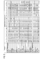
- Co-30NI-28Cr-8Al-0.6Y-0.7Si Co-30NI-28Cr-8Al-0.6Y-0.7Si.
- the layer 7 consists of one of the abovementioned alloys.
- the FIG. 2 shows by way of example a gas turbine 100 in a longitudinal partial section.
- the gas turbine 100 has inside a rotatably mounted about a rotation axis 102 rotor 103 with a shaft 101, which is also referred to as a turbine runner.
- a compressor 105 for example, a toroidal combustion chamber 110, in particular annular combustion chamber, with a plurality of coaxially arranged burners 107, a turbine 108 and the exhaust housing 109th
- the annular combustion chamber 110 communicates with an annular annular hot gas channel 111, for example.
- Each turbine stage 112 is formed, for example, from two blade rings. As seen in the direction of flow of a working medium 113, in the hot gas channel 111 of a row of guide vanes 115, a series 125 formed of rotor blades 120 follows.
- the guide vanes 130 are fastened to an inner housing 138 of a stator 143, whereas the moving blades 120 of a row 125 are attached to the rotor 103 by means of a turbine disk 133, for example.
- air 105 is sucked in and compressed by the compressor 105 through the intake housing 104.
- the compressed air provided at the turbine-side end of the compressor 105 is supplied to the burners 107 where it is mixed with a fuel.
- the mixture is then burned to form the working fluid 113 in the combustion chamber 110.
- the working medium 113 flows along the hot gas channel 111 past the guide vanes 130 and the rotor blades 120.
- the working medium 113 expands in a pulse-transmitting manner so that the rotor blades 120 drive the rotor 103 and drive the machine coupled to it.
- the components exposed to the hot working medium 113 are subject to thermal loads during operation of the gas turbine 100.
- the guide vanes 130 and rotor blades 120 of the first turbine stage 112, viewed in the flow direction of the working medium 113, are subjected to the greatest thermal stress in addition to the heat shield elements lining the annular combustion chamber 110. To withstand the prevailing temperatures, they can be cooled by means of a coolant.
- substrates of the components can have a directional structure, ie they are monocrystalline (SX structure) or have only longitudinal grains (DS structure).
- SX structure monocrystalline
- DS structure only longitudinal grains
- Such superalloys are for example from EP 1 204 776 B1 .
- EP 1 306 454 .
- the vane 130 has a guide vane foot (not shown here) facing the inner housing 138 of the turbine 108 and a vane head opposite the vane foot.
- the vane head faces the rotor 103 and fixed to a mounting ring 140 of the stator 143.
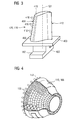
- FIG. 3 shows a perspective view of a blade 120 or guide vane 130 of a turbomachine, which extends along a longitudinal axis 121.
- the turbomachine may be a gas turbine of an aircraft or a power plant for power generation, a steam turbine or a compressor.
- the blade 120, 130 has along the longitudinal axis 121 consecutively a fastening region 400, a blade platform 403 adjacent thereto and an airfoil 406 and a blade tip 415. As a guide blade 130, the blade 130 may have at its blade tip 415 another platform (not shown).
- a blade root 183 is formed, which serves for attachment of the blades 120, 130 to a shaft or a disc (not shown).
- the blade root 183 is designed, for example, as a hammer head. Other designs as Christmas tree or Schwalbenschwanzfuß are possible.
- the blade 120, 130 has a leading edge 409 and a trailing edge 412 for a medium flowing past the airfoil 406.
- Such superalloys are for example from EP 1 204 776 B1 .
- EP 1 306 454 .
- the blade 120, 130 can be made by a casting process, also by directional solidification, by a forging process, by a milling process or combinations thereof.
- directionally solidified microstructures which means both single crystals that have no grain boundaries or at most small angle grain boundaries, and stem crystal structures that have probably longitudinal grain boundaries but no transverse grain boundaries.
- second-mentioned crystalline structures are also known as directionally solidified structures.
- the blades 120, 130 may have coatings against corrosion or oxidation, e.g. M is at least one element of the group iron (Fe), cobalt (Co), nickel (Ni), X is an active element and stands for yttrium (Y) and / or silicon and / or at least one element of the rare ones Earth, or hafnium (Hf)).
- M is at least one element of the group iron (Fe), cobalt (Co), nickel (Ni)
- X is an active element and stands for yttrium (Y) and / or silicon and / or at least one element of the rare ones Earth, or hafnium (Hf)).
- Such alloys are known from the EP 0 486 489 B1 . EP 0 786 017 B1 . EP 0 412 397 B1 or EP 1 306 454 A1 which are to be part of this disclosure with regard to the chemical composition of the alloy.
- the density is preferably 95% of the theoretical density.
- thermal barrier coating which is preferably the outermost layer, and consists for example of ZrO 2 , Y 2 O 3 -ZrO 2 , ie it is not, partially or completely stabilized by yttria and / or calcium oxide and / or magnesium oxide.
- the thermal barrier coating covers the entire MCrAlX layer.
- suitable coating processes such as electron beam evaporation (EB-PVD)
- stalk-shaped grains are produced in the thermal barrier coating.
- Other coating methods are conceivable, for example atmospheric plasma spraying (APS), LPPS, VPS or CVD.
- the thermal barrier coating may have porous, micro- or macro-cracked grains for better thermal shock resistance.
- the thermal barrier coating is therefore preferably more porous than the MCrAlX layer.
- the blade 120, 130 may be hollow or solid.
- the blade 120, 130 is to be cooled, it is hollow and may still film cooling holes 418 (indicated by dashed lines) on.
- the FIG. 4 shows a combustion chamber 110 of the gas turbine 100.
- the combustion chamber 110 is configured, for example, as a so-called annular combustion chamber, in which a plurality of circumferentially arranged around a rotation axis 102 around burners 107 open into a common combustion chamber space 154, the flames 156 produce.
- the combustion chamber 110 is configured in its entirety as an annular structure, which is positioned around the axis of rotation 102 around.
- the combustion chamber 110 is designed for a comparatively high temperature of the working medium M of about 1000 ° C to 1600 ° C.
- the combustion chamber wall 153 is provided on its side facing the working medium M side with an inner lining formed from heat shield elements 155.
- the heat shield elements 155 are then, for example, hollow and possibly still have cooling holes (not shown) which open into the combustion chamber space 154.
- Each heat shield element 155 made of an alloy is equipped on the working medium side with a particularly heat-resistant protective layer (MCrAlX layer and / or ceramic coating) or is made of high-temperature-resistant material (solid ceramic blocks).
- M is at least one element of the group iron (Fe), cobalt (Co), nickel (Ni), X is an active element and stands for yttrium (Y) and / or silicon and / or at least one element of the rare earths, or hafnium (Hf).
- MCrAlX means: M is at least one element of the group iron (Fe), cobalt (Co), nickel (Ni), X is an active element and stands for yttrium (Y) and / or silicon and / or at least one element of the rare earths, or hafnium (Hf).
- Such alloys are known from the EP 0 486 489 B1 .
- a ceramic thermal barrier coating may be present and consists for example of ZrO 2 , Y 2 O 3 -ZrO 2 , ie it is not, partially or completely stabilized by yttria and / or calcium oxide and / or magnesium oxide.
- suitable coating processes such as electron beam evaporation (EB-PVD)
- stalk-shaped grains are produced in the thermal barrier coating.
- APS atmospheric plasma spraying
- LPPS LPPS
- VPS vacuum plasma spraying
- CVD chemical vaporation
- the thermal barrier coating may have porous, micro- or macro-cracked grains for better thermal shock resistance.
- Refurbishment means that turbine blades 120, 130, heat shield elements 155 may need to be deprotected (e.g., by sandblasting) after use. This is followed by removal of the corrosion and / or oxidation layers or products. Optionally, cracks in the turbine blade 120, 130 or the heat shield element 155 are also repaired. This is followed by a re-coating of the turbine blades 120, 130, heat shield elements 155 and a renewed use of the turbine blades 120, 130 or the heat shield elements 155.
Landscapes
- Engineering & Computer Science (AREA)
- Chemical & Material Sciences (AREA)
- Materials Engineering (AREA)
- Mechanical Engineering (AREA)
- General Engineering & Computer Science (AREA)
- Chemical Kinetics & Catalysis (AREA)
- Metallurgy (AREA)
- Organic Chemistry (AREA)
- Ceramic Engineering (AREA)
- Turbine Rotor Nozzle Sealing (AREA)
- Other Surface Treatments For Metallic Materials (AREA)
Priority Applications (4)
| Application Number | Priority Date | Filing Date | Title |
|---|---|---|---|
| EP06025146A EP1932935A1 (fr) | 2006-12-05 | 2006-12-05 | Procédé de fabrication d'une aube de turbine avec une couche d'oxide, une aube de turbine et son utilisation, et procédé de fonctionnement d'une turbine |
| EP07803292.7A EP2102379B1 (fr) | 2006-12-05 | 2007-09-06 | Procédé d'utilisation d'une turbine qui présente un oxyde sur une couche métallique et une turbine |
| US12/517,585 US20100061836A1 (en) | 2006-12-05 | 2007-09-06 | Process for producing a turbine blade or vane with an oxide on a metallic layer, use of such a turbine blade or vane, a turbine and a method for operating a turbine |
| PCT/EP2007/059337 WO2008068069A1 (fr) | 2006-12-05 | 2007-09-06 | Procédé de fabrication d'une aube de turbine qui présente un oxyde sur une couche métallique, utilisation de cette aube de turbine, turbine et procédé d'utilisation d'une turbine |
Applications Claiming Priority (1)
| Application Number | Priority Date | Filing Date | Title |
|---|---|---|---|
| EP06025146A EP1932935A1 (fr) | 2006-12-05 | 2006-12-05 | Procédé de fabrication d'une aube de turbine avec une couche d'oxide, une aube de turbine et son utilisation, et procédé de fonctionnement d'une turbine |
Publications (1)
| Publication Number | Publication Date |
|---|---|
| EP1932935A1 true EP1932935A1 (fr) | 2008-06-18 |
Family
ID=37692524
Family Applications (2)
| Application Number | Title | Priority Date | Filing Date |
|---|---|---|---|
| EP06025146A Withdrawn EP1932935A1 (fr) | 2006-12-05 | 2006-12-05 | Procédé de fabrication d'une aube de turbine avec une couche d'oxide, une aube de turbine et son utilisation, et procédé de fonctionnement d'une turbine |
| EP07803292.7A Not-in-force EP2102379B1 (fr) | 2006-12-05 | 2007-09-06 | Procédé d'utilisation d'une turbine qui présente un oxyde sur une couche métallique et une turbine |
Family Applications After (1)
| Application Number | Title | Priority Date | Filing Date |
|---|---|---|---|
| EP07803292.7A Not-in-force EP2102379B1 (fr) | 2006-12-05 | 2007-09-06 | Procédé d'utilisation d'une turbine qui présente un oxyde sur une couche métallique et une turbine |
Country Status (3)
| Country | Link |
|---|---|
| US (1) | US20100061836A1 (fr) |
| EP (2) | EP1932935A1 (fr) |
| WO (1) | WO2008068069A1 (fr) |
Cited By (1)
| Publication number | Priority date | Publication date | Assignee | Title |
|---|---|---|---|---|
| WO2016107710A1 (fr) * | 2014-12-30 | 2016-07-07 | Siemens Aktiengesellschaft | Thermoélément et procédé pour l'appliquer |
Citations (5)
| Publication number | Priority date | Publication date | Assignee | Title |
|---|---|---|---|---|
| US4414249A (en) * | 1980-01-07 | 1983-11-08 | United Technologies Corporation | Method for producing metallic articles having durable ceramic thermal barrier coatings |
| US5856027A (en) * | 1995-03-21 | 1999-01-05 | Howmet Research Corporation | Thermal barrier coating system with intermediate phase bondcoat |
| EP1127959A1 (fr) * | 2000-02-23 | 2001-08-29 | Howmet Research Corporation | Revêtement de barrière thermique et article |
| EP1273681A2 (fr) * | 2001-07-06 | 2003-01-08 | General Electric Company | Procédé pour améliorer la durée de vie d'un revêtement de barrière thermique d'une couche de liaison monophase d'aluminure de platine par traitement de préoxydation |
| EP1600518A2 (fr) * | 2004-05-27 | 2005-11-30 | General Electric Company | Revêtement à base d'aluminiure de nickel amelioré ayant un oxyde de structure stable |
Family Cites Families (9)
| Publication number | Priority date | Publication date | Assignee | Title |
|---|---|---|---|---|
| US5683825A (en) * | 1996-01-02 | 1997-11-04 | General Electric Company | Thermal barrier coating resistant to erosion and impact by particulate matter |
| EP0861927A1 (fr) * | 1997-02-24 | 1998-09-02 | Sulzer Innotec Ag | Procédé de fabrication de structures monocristallines |
| US6514629B1 (en) * | 1998-12-15 | 2003-02-04 | General Electric Company | Article with hafnium-silicon-modified platinum-aluminum bond or environmental coating |
| UA71572C2 (uk) * | 1999-08-04 | 2004-12-15 | Дженерал Електрік Компані | Електронно-променевий пристрій для нанесення покриття на вироби конденсацією із парової фази |
| US6499938B1 (en) * | 2001-10-11 | 2002-12-31 | General Electric Company | Method for enhancing part life in a gas stream |
| US20040191488A1 (en) * | 2002-04-10 | 2004-09-30 | Thomas Berndt | Component, method for coating a component, and powder |
| EP1380672A1 (fr) * | 2002-07-09 | 2004-01-14 | Siemens Aktiengesellschaft | Composant à haute résistance contre l'oxydation |
| US7413778B2 (en) * | 2005-12-05 | 2008-08-19 | General Electric Company | Bond coat with low deposited aluminum level and method therefore |
| EP1925687A1 (fr) * | 2006-11-24 | 2008-05-28 | Siemens Aktiengesellschaft | Couche à base d'un alliage en NiCoCrAl et système de couches |
-
2006
- 2006-12-05 EP EP06025146A patent/EP1932935A1/fr not_active Withdrawn
-
2007
- 2007-09-06 WO PCT/EP2007/059337 patent/WO2008068069A1/fr not_active Ceased
- 2007-09-06 US US12/517,585 patent/US20100061836A1/en not_active Abandoned
- 2007-09-06 EP EP07803292.7A patent/EP2102379B1/fr not_active Not-in-force
Patent Citations (5)
| Publication number | Priority date | Publication date | Assignee | Title |
|---|---|---|---|---|
| US4414249A (en) * | 1980-01-07 | 1983-11-08 | United Technologies Corporation | Method for producing metallic articles having durable ceramic thermal barrier coatings |
| US5856027A (en) * | 1995-03-21 | 1999-01-05 | Howmet Research Corporation | Thermal barrier coating system with intermediate phase bondcoat |
| EP1127959A1 (fr) * | 2000-02-23 | 2001-08-29 | Howmet Research Corporation | Revêtement de barrière thermique et article |
| EP1273681A2 (fr) * | 2001-07-06 | 2003-01-08 | General Electric Company | Procédé pour améliorer la durée de vie d'un revêtement de barrière thermique d'une couche de liaison monophase d'aluminure de platine par traitement de préoxydation |
| EP1600518A2 (fr) * | 2004-05-27 | 2005-11-30 | General Electric Company | Revêtement à base d'aluminiure de nickel amelioré ayant un oxyde de structure stable |
Cited By (1)
| Publication number | Priority date | Publication date | Assignee | Title |
|---|---|---|---|---|
| WO2016107710A1 (fr) * | 2014-12-30 | 2016-07-07 | Siemens Aktiengesellschaft | Thermoélément et procédé pour l'appliquer |
Also Published As
| Publication number | Publication date |
|---|---|
| WO2008068069A1 (fr) | 2008-06-12 |
| EP2102379B1 (fr) | 2013-06-26 |
| US20100061836A1 (en) | 2010-03-11 |
| EP2102379A1 (fr) | 2009-09-23 |
Similar Documents
| Publication | Publication Date | Title |
|---|---|---|
| EP2436798B1 (fr) | Matériel de masquage, couche de masquage et procédé de masquage d'un substrat | |
| EP2593582B1 (fr) | Système stratifié céramique poreux | |
| EP2458025B1 (fr) | Alliage, couche de protection et composant | |
| EP2907888A1 (fr) | Aube de compresseur dotée d'un revêtement dur résistant à la corrosion | |
| EP2614174A1 (fr) | Système à couches poreux, muni d'une couche interne poreuse | |
| WO2009138299A1 (fr) | Procédé de réalisation d'une couche promotrice d'adhésion optimisée par évaporation partielle de la couche promotrice d'adhésion et système de revêtement | |
| EP2904211A1 (fr) | Surface modifiée autour d'un trou | |
| EP2742171B1 (fr) | Couche double céramique à base d'oxyde de zirconium | |
| WO2010078994A1 (fr) | Procédé pour recouvrir un composant pourvu de trous de refroidissement pelliculaire et composant | |
| EP2710167B1 (fr) | Alliage, couche de protection et composant | |
| EP2756107B1 (fr) | Alliage, couche de protection et composant | |
| WO2011107167A1 (fr) | Système de couche d'isolation thermique céramique à couche de liaison modifiée | |
| EP2227346A2 (fr) | Brasage de trous, procédé de revêtement et baguettes de brasure | |
| EP1816222A1 (fr) | Système de revêtements de couches métalliques protectrices à double couche | |
| EP2584067A1 (fr) | Composant avec graphène et procédé de fabrication de composants avec graphène | |
| EP1798299B1 (fr) | Alliage, couche de protection et élément de construction | |
| EP2661370B1 (fr) | Alliage, couche protectrice et pièce | |
| EP2611949B1 (fr) | Alliage a base nickel, couche de protection et élément de construction | |
| EP2102379B1 (fr) | Procédé d'utilisation d'une turbine qui présente un oxyde sur une couche métallique et une turbine | |
| EP1806430A1 (fr) | Revêmtement céramique ayant une haute porositée, utilisation de celle-ci revêtement et composant comprenant telle revêtement | |
| EP2322683B1 (fr) | Procédé de revêtement d'un composant doté d'un orifice partiellement fermé et procédé d'ouverture de l'orifice | |
| EP1806419B1 (fr) | Alliage, couche protectrice pour proteger un élément structurel contre la corrosion et l'oxydation aux temperatures hautes, et élément structurel | |
| EP2589681A1 (fr) | Combinaison de structures colonnaires et globulaires | |
| WO2011057661A1 (fr) | Composant comportant des zones de ductilité différente et procédé de fabrication d'un composant | |
| EP2345748A1 (fr) | Alliage, couche de protection et composant |
Legal Events
| Date | Code | Title | Description |
|---|---|---|---|
| PUAI | Public reference made under article 153(3) epc to a published international application that has entered the european phase |
Free format text: ORIGINAL CODE: 0009012 |
|
| AK | Designated contracting states |
Kind code of ref document: A1 Designated state(s): AT BE BG CH CY CZ DE DK EE ES FI FR GB GR HU IE IS IT LI LT LU LV MC NL PL PT RO SE SI SK TR |
|
| AX | Request for extension of the european patent |
Extension state: AL BA HR MK RS |
|
| AKX | Designation fees paid | ||
| STAA | Information on the status of an ep patent application or granted ep patent |
Free format text: STATUS: THE APPLICATION IS DEEMED TO BE WITHDRAWN |
|
| 18D | Application deemed to be withdrawn |
Effective date: 20081219 |