EP1932974A1 - Versickerungsmodul - Google Patents
Versickerungsmodul Download PDFInfo
- Publication number
- EP1932974A1 EP1932974A1 EP06026074A EP06026074A EP1932974A1 EP 1932974 A1 EP1932974 A1 EP 1932974A1 EP 06026074 A EP06026074 A EP 06026074A EP 06026074 A EP06026074 A EP 06026074A EP 1932974 A1 EP1932974 A1 EP 1932974A1
- Authority
- EP
- European Patent Office
- Prior art keywords
- module according
- infiltration module
- infiltration
- cube
- webs
- Prior art date
- Legal status (The legal status is an assumption and is not a legal conclusion. Google has not performed a legal analysis and makes no representation as to the accuracy of the status listed.)
- Granted
Links
- 230000008595 infiltration Effects 0.000 title claims description 48
- 238000001764 infiltration Methods 0.000 title claims description 48
- 238000003780 insertion Methods 0.000 claims abstract description 42
- 230000037431 insertion Effects 0.000 claims abstract description 42
- XLYOFNOQVPJJNP-UHFFFAOYSA-N water Substances O XLYOFNOQVPJJNP-UHFFFAOYSA-N 0.000 claims description 8
- 230000002093 peripheral effect Effects 0.000 claims description 2
- 238000007689 inspection Methods 0.000 description 9
- 238000005325 percolation Methods 0.000 description 5
- 238000004140 cleaning Methods 0.000 description 3
- 230000002349 favourable effect Effects 0.000 description 3
- 238000002347 injection Methods 0.000 description 2
- 239000007924 injection Substances 0.000 description 2
- 239000002689 soil Substances 0.000 description 2
- 238000010521 absorption reaction Methods 0.000 description 1
- 230000008878 coupling Effects 0.000 description 1
- 238000010168 coupling process Methods 0.000 description 1
- 238000005859 coupling reaction Methods 0.000 description 1
- 238000007599 discharging Methods 0.000 description 1
- 238000009434 installation Methods 0.000 description 1
- 239000000463 material Substances 0.000 description 1
- 238000007493 shaping process Methods 0.000 description 1
Images
Classifications
-
- E—FIXED CONSTRUCTIONS
- E03—WATER SUPPLY; SEWERAGE
- E03F—SEWERS; CESSPOOLS
- E03F1/00—Methods, systems, or installations for draining-off sewage or storm water
- E03F1/002—Methods, systems, or installations for draining-off sewage or storm water with disposal into the ground, e.g. via dry wells
- E03F1/005—Methods, systems, or installations for draining-off sewage or storm water with disposal into the ground, e.g. via dry wells via box-shaped elements
-
- B—PERFORMING OPERATIONS; TRANSPORTING
- B29—WORKING OF PLASTICS; WORKING OF SUBSTANCES IN A PLASTIC STATE IN GENERAL
- B29C—SHAPING OR JOINING OF PLASTICS; SHAPING OF MATERIAL IN A PLASTIC STATE, NOT OTHERWISE PROVIDED FOR; AFTER-TREATMENT OF THE SHAPED PRODUCTS, e.g. REPAIRING
- B29C45/00—Injection moulding, i.e. forcing the required volume of moulding material through a nozzle into a closed mould; Apparatus therefor
- B29C45/17—Component parts, details or accessories; Auxiliary operations
- B29C45/26—Moulds
- B29C45/33—Moulds having transversely, e.g. radially, movable mould parts
-
- Y—GENERAL TAGGING OF NEW TECHNOLOGICAL DEVELOPMENTS; GENERAL TAGGING OF CROSS-SECTIONAL TECHNOLOGIES SPANNING OVER SEVERAL SECTIONS OF THE IPC; TECHNICAL SUBJECTS COVERED BY FORMER USPC CROSS-REFERENCE ART COLLECTIONS [XRACs] AND DIGESTS
- Y02—TECHNOLOGIES OR APPLICATIONS FOR MITIGATION OR ADAPTATION AGAINST CLIMATE CHANGE
- Y02A—TECHNOLOGIES FOR ADAPTATION TO CLIMATE CHANGE
- Y02A10/00—TECHNOLOGIES FOR ADAPTATION TO CLIMATE CHANGE at coastal zones; at river basins
- Y02A10/30—Flood prevention; Flood or storm water management, e.g. using flood barriers
-
- Y—GENERAL TAGGING OF NEW TECHNOLOGICAL DEVELOPMENTS; GENERAL TAGGING OF CROSS-SECTIONAL TECHNOLOGIES SPANNING OVER SEVERAL SECTIONS OF THE IPC; TECHNICAL SUBJECTS COVERED BY FORMER USPC CROSS-REFERENCE ART COLLECTIONS [XRACs] AND DIGESTS
- Y02—TECHNOLOGIES OR APPLICATIONS FOR MITIGATION OR ADAPTATION AGAINST CLIMATE CHANGE
- Y02A—TECHNOLOGIES FOR ADAPTATION TO CLIMATE CHANGE
- Y02A20/00—Water conservation; Efficient water supply; Efficient water use
- Y02A20/40—Protecting water resources
Definitions
- the invention relates to a percolation module made of plastic according to the preamble of patent claim 1.
- the end EP 1 260 640 A known infiltration module is formed either of two mirror-image subunits, or is in one piece, so that a continuous inspection channel is kept free between two side walls facing away from each other.
- the width of the inspection channel is about one third of the side length of the module.
- support columns run between the cover plate and the base plate.
- a known infiltration module is an elongated cuboid lattice structure box, in which two side walls facing away from each other are covered over the entire surface. Between these side walls extend circular continuous inspection channels whose mouths lie in the panels. Inside the infiltration module, a cross connection between the inspection channels is formed.
- the invention is based on the object to provide a percolation module of the type mentioned, which has minimal design cost optimum strength and optimal capacity, is easy to handle, and allows the creation of arbitrarily large, drivable infiltration systems, which can be optionally inspected at different locations.
- the geometrically clear cube shape with the insertion openings in the outer walls provides optimal design strength and maximum absorption capacity with minimum use of material.
- the module can be combined with the same modules to any size infiltration systems, is easy to handle, and allows for removal of the insert plate an unobstructed inspection or cleaning.
- the lattice structure of the body is not necessarily water permeable, but the insertion plates allow the entry or exit of the water. Thanks to the insert plates used, a flat, large-area support is guaranteed for an enveloping nonwoven layer. In the case of several layers of such infiltration modules arranged one above another, no intermediate plate is required since the top wall of a module forms the base plate for the module placed thereon.
- each module can be conveniently close together and connect with each other.
- the insertion opening size is selected so that upon removal an insertion plate is readily accessible for inspection or cleaning, and it is advantageous that each interior chamber of a module is free of struts and support columns.
- the Einsetzö Stammsest is chosen so that each module has optimal structural strength, ie, defined by the insertion openings in the base body support columns are very stable and remove loads in the vertical direction as well as in the horizontal direction.
- inner linings of the insertion openings contribute to the rigidity and kink resistance.
- the linings at least partially with the grid structure communicating passages.
- Such passages may also be used to anchor the insert plates (e.g., snap-fit connections).
- each insert plate is increased by a circumferential panel.
- This trim also improves the fit of the built-in insert plate in the insertion opening and may include snap-in elements.
- the thickness of the insert plate and the outline contour of its peripheral panel are chosen so that the free inner chamber of the module equipped with insert plates has no edges or shoulders on which dirt could settle. It is formed as a smooth inner chamber.
- a cutting pattern is incorporated into the grid structure in each inserting plate. This cut-out pattern can be designed for different pipe diameters and cut out accordingly.
- the lattice structures comprise transverse and longitudinal webs which cross each other at right angles and which delimit predominantly equal square patches. This achieves a uniform load transfer under loads from different directions.
- integrated, ribbed and non-permeable or only partially water-permeable stiffening profiles are provided along the cube edges in the grid structures. These profiles are thus located at statically favorable locations and, so to speak, form supporting skeletons integrated in the support columns, so that the inner chamber remains completely free, yet high structural strength is achieved.
- each stiffening profiling between which a bisecting longitudinal web is inserted.
- These three longitudinal webs are stiffened by extended cross bars of the lattice structure.
- the cube corners can be reinforced by the fact that at each cube corner in addition three diagonal webs are brought together there a favorable for wrapping fleece rounding or dome is formed.
- the outline contour of each insertion opening has rounded corner areas and symmetrical sections connecting the corner areas and concavely curved outward.
- the curvature of the symmetrical sections is flatter than the curvature in the rounding of each corner area.
- each insert plate is releasably fixable in the insertion opening, e.g. with the mentioned snap connection, so that they can be removed again at any time and used again.
- the infiltration module is a one-piece injection molded part and may have a side length of about 0.5 m to 1.2 m. With this dimensioning, the infiltration modules are easy to handle and can also be used to create large infiltration systems.
- the infiltration module could, e.g. for smaller sizes, consist of several already integrally molded with each other cubes.
- the basic body must be made up of individually shaped parts.
- the infiltration module M is a plastic injection molded part in one-piece design and is produced for example in a so-called baking mold.
- the infiltration module M is used to create infiltration systems such as in the Fig. 3 and 4 indicated.
- One purpose of such infiltration systems is to store excess rainwater and leach it into the surrounding soil.
- the infiltration plant V ( Fig. 3 and 4 ) to a drain having at least one coarse filter and also, if appropriate, to be connected to the secondary sewerage system.
- the infiltration system is installed underground, often under traffic areas that are used by passenger cars and possibly even by lorries.
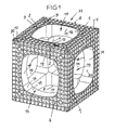
- FIG. 1 shown infiltration module M has a main body G with the shape of a cube with six outer walls 1, 4, 5, 6, 7 and 8, which are exactly and mutually exactly perpendicular.
- Each outer wall is a lattice structure of longitudinal and transverse webs 2, 3, which stand upright and square, in the embodiment shown even square and equally large fields limit.
- the side length of the cube is for example between 0.8 m to 1.1 m.
- counter-receptacles 9 are formed in the grid structures, which serve for attaching connecting elements (not shown) to install and couple several infiltration modules side by side and / or one above the other.
- a non-or only partially water-permeable stiffening profiling 10 is integrally formed, which in the embodiment shown consists of mutually perpendicular longitudinal webs 11 and 12, between which a bisecting longitudinal web 13 is formed, which is the actual edge of the cube Are defined. Furthermore, the transverse webs 2 are extended in this area of the stiffening profiling 10.
- the cube corners are additionally reinforced by three diagonal webs 20 are brought together at each cube corner. There are rounded or dome-shaped corner areas appropriate.
- a rectangular or approximately square insertion opening 14 is formed in at least substantially central arrangement, which leads to an inner, free chamber 19.
- the insertion openings 14 are only approximately square, since they have rounded corner regions 16 and the corner regions 16 connecting, symmetrical concavely curved portions 17 having a continuous lining 15 in this embodiment.
- the linings 15 of the insertion openings 14 in the body G along the edge regions define a total of eight waisted columns 18. This means that the lattice structures 2, 3 of the outer walls are not necessarily permeable to water to the inner chamber 19, although possibly (indicated by dashed lines). local passages 24 may be formed.
- the inner chamber 19 of the body K is free and relatively smooth.
- the longitudinal and transverse webs 2, 3, are upright, i. Shaped parallel to the outer walls.
- the opening size of the insertion openings 14 is between 30 and 60% of the respective outer wall surface, preferably about 35%.
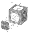
- the infiltration module M is combined with additional components, namely insertion plates 21, which are optionally inserted into insertion openings 14 until they are flush with the outer wall.
- additional components namely insertion plates 21, which are optionally inserted into insertion openings 14 until they are flush with the outer wall.
- insertion plates 21 which are optionally inserted into insertion openings 14 until they are flush with the outer wall.
- the insert plate 21 has a grid structure of longitudinal and transverse webs 2 ', 3', at least partially is permeable to water.
- the insertion plate 21 has a continuous covering 23, which fits as a fitting surface in the lining 15 of the insertion opening 14.
- locking or fastening elements or snap elements are used for releasably securing the insertion plate 21 (not shown), or the passages 24 are used for this purpose.
- the insert plate 21 is, preferably, a Ausschneidemuster 22 integrated, for example in the form of concentric circular webs.
- This cut-out pattern 22 is used to expose the respective desired opening size for connecting a raw string, not shown.
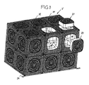
- Fig. 3 illustrates an on-going infiltration system V for underground installation.
- the infiltration system V consists of an upper and a lower layer each of six percolation modules M, which are set with their outer wall surfaces directly to each other and (not shown), preferably, for example via molded or inserted coupling elements, connected to each other.
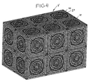
- insertion openings 14 are still released some, but the completion of the infiltration system V ( Fig. 4 ) are still used.
- the internal chambers of the individual infiltration modules communicate freely with each other.
- each insert plate 21 can optionally be removed, for example also to perform a cleaning cycle.
- the insertion plates 21 used on the outer walls of the infiltration system V define with the outer walls relatively flat support surfaces for at least one enveloping nonwoven layer, as is usually provided in such infiltration systems. Feeding or dissipating pipe strands can be connected or inserted as desired using the frequently provided cut-out patterns.
- the infiltration system V is used either directly in the soil, or on a base plate or a foundation 24, the z. B. is permeable to water.
- one of the overhead insertion holes could be used for the introduction of a manhole or gully (for water supply and / or for inspection purposes).
- a base G could be assembled from individually manufactured parts.
Landscapes
- Health & Medical Sciences (AREA)
- Life Sciences & Earth Sciences (AREA)
- Engineering & Computer Science (AREA)
- Hydrology & Water Resources (AREA)
- Public Health (AREA)
- Water Supply & Treatment (AREA)
- Separation By Low-Temperature Treatments (AREA)
- Sewage (AREA)
- Orthopedics, Nursing, And Contraception (AREA)
- Prostheses (AREA)
- Cultivation Receptacles Or Flower-Pots, Or Pots For Seedlings (AREA)
Abstract
Description
- Die Erfindung betrifft ein Versickerungsmodul aus Kunststoff entsprechend dem Oberbegriff des Patentanspruchs 1.
- Das aus der Broschüre V26EN, Edition 2006/2007, "Stormwater Management" der Firma Otto Graf GmbH, D-79331 Teningen, DE, Seiten 4 und 5, bekannte Versickerungsmodul ist ein quaderförmiger Gitterstrukturkasten, in dessen Innenkammern von der Deckplatte zur Grundplatte verlaufende Stützsäulen vorgesehen sind.
- Das aus
EP 1 260 640 A bekannte Versickerungsmodul wird entweder aus zwei spiegelbildlich zusammengesetzten Untereinheiten gebildet, oder ist einstückig, derart dass zwischen zwei voneinander abgewandten Seitenwänden ein durchgehender Inspektionskanal freigehalten bleibt. Die Weite des Inspektionskanals beträgt ca. ein Drittel der Seitenlänge des Moduls. In den Hohlräumen zwischen den Außenwänden und dem Inspektionskanal verlaufen Stützsäulen zwischen der Deckplatte und der Grundplatte. - Das aus
EP 1 607 535 A bekannte Versickerungsmodul ist ein langgestreckter quaderförmiger Gitterstrukturkasten, bei dem zwei voneinander wegweisende Seitenwände vollflächig verkleidet sind. Zwischen diesen Seitenwänden erstrecken sich kreisrunde durchgehende Inspektionskanäle, deren Mündungen in den Verkleidungen liegen. Im Inneren des Versickerungsmoduls ist eine Querverbindung zwischen den Inspektionskanälen geformt. - Der Erfindung liegt die Aufgabe zu Grunde, ein Versickerungsmodul der eingangs genannten Art zu schaffen, das mit minimalem Materialaufwand optimale Gestaltfestigkeit und optimales Aufnahmevermögen hat, einfach handhabbar ist, und die Erstellung beliebig großer, befahrbarer Versickerungsanlagen ermöglicht, die an verschiedenen Stellen wahlweise inspizierbar sind.
- Die gestellte Aufgabe wird mit den Merkmalen des Patentanspruchs 1 gelöst.
- Die geometrisch klare Würfelform mit den Einsetzöffnungen in den Außenwänden erbringt bei minimalem Materialeinsatz optimale Gestalt-Festigkeit und ein maximales Aufnahmevermögen. Das Modul lässt sich mit gleichen Modulen zu beliebig großen Versickerungsanlagen kombinieren, ist einfach handhabbar, und ermöglicht nach Entnahme der Einsetzplatte eine unbehinderte Inspektion bzw. Reinigung. Die Gitterstruktur des Grundkörpers ist nicht notwendiger Weise wasserdurchlässig, sondern die Einsetzplatten ermöglichen den Eintritt bzw. Austritt des Wassers. Dank der eingesetzten Einsetzplatten wird für eine umhüllende Vlieslage eine ebene großflächige Abstützung gewährleistet. Bei mehreren übereinander angeordneten Lagen aus solchen Versickerungsmodulen wird keine Zwischenplatte benötigt, da die Deckwand eines Moduls jeweils die Grundplatte für das darauf gesetzte Modul bildet. Da die Außenwände eben und senkrecht zu einander sind, lassen sich die Module bequem ganz dicht aneinander setzen und miteinander verbinden. Die Einsetzöffnungsgröße ist so gewählt, dass nach Entnahme eine Einsetzplatte bequem Zugang zur Inspektion bzw. zur Reinigung vorliegt, wobei es von Vorteil ist, dass jede Innenkammer eines Moduls frei ist von Verstrebungen und Stützsäulen. Andererseits ist die Einsetzöffnungsgröße so gewählt, dass jedes Modul optimale Gestaltfestigkeit hat, d.h., durch die Einsetzöffnungen im Grundkörper definierte Stützsäulen sehr stabil sind und Lasten in vertikaler Richtung wie in horizontaler Richtung gut abtragen.
- Dabei tragen bei einer Ausführungsform innenseitige Auskleidungen der Einsetzöffnungen zur Steifigkeit und Knick-Festigkeit bei.
- Es ist allerdings möglich, die Auskleidungen zumindest bereichsweise mit der Gitterstruktur kommunizierenden Durchlässen zu versehen. Solche Durchlässe können auch zum Verankern der Einsetzplatten herangezogen werden (z.B. Schnappverbindungen).
- Die Gestaltfestigkeit jeder Einsetzplatte wird durch eine umfängliche Verkleidung erhöht. Diese Verkleidung verbessert auch den Sitz der eingebauten Einsetzplatte in der Einsetzöffnung und kann Elemente zum Einschnappen aufweisen. Die Dicke der Einsetzplatte und die Umrisskontur ihrer umfänglichen Verkleidung sind so gewählt, dass die freie Innenkammer des mit Einsetzplatten bestückten Moduls keine Kanten oder Schultern hat, an denen sich Verschmutzungen absetzen könnten. Es wird so eine glatte Innenkammer gebildet.
- Um zuleitende oder ableitende Rohre anschließen zu können, ist, vorzugsweise, in jeder Einsetzplatte ein Ausschneidemuster in die Gitterstruktur eingegliedert. Dieses Ausschneidemuster kann für unterschiedliche Rohrdurchmesser konzipiert und entsprechend ausgeschnitten werden.
- Bei einer zweckmäßigen Ausführungsform umfassen die Gitterstrukturen einander rechtwinkelig kreuzende Quer- und Längsstege, die überwiegend gleichgroße quadratische Felder begrenzen. Hierdurch wird eine gleichförmige Lastabtragung unter Lasten aus verschiedenen Richtungen erzielt.
- Bei einer bevorzugten Ausführungsform sind entlang der Würfelkanten in die Gitterstrukturen integrierte, verrippte und nicht oder nur teilweise wasserdurchlässige Aussteifungs-Profilierungen vorgesehen. Diese Profilierungen befinden sich somit an statisch günstigen Stellen und bilden sozusagen in die Stützsäulen integrierte tragende Skelette, so dass die Innenkammer vollständig frei bleibt, und dennoch hohe Gestaltfestigkeit erzielt wird.
- Zweckmäßig sind in jeder Aussteifungs-Profilierung zwei senkrecht zueinander geführte Längsstege vorgesehen, zwischen denen ein winkelhalbierender Längssteg eingesetzt ist. Diese drei Längsstege werden durch verlängerte Querstäbe der Gitterstruktur ausgesteift.
- Zusätzlich können die Würfelecken dadurch verstärkt sein, dass an jeder Würfelecke zusätzlich drei Diagonalstege zusammengeführt sind Dort wird eine für umhüllendes Vlies günstige Rundung oder Kuppe gebildet.
- Bei einer zweckmäßigen Ausführungsform weist die Umrisskontur jeder Einsetzöffnung gerundete Eckbereiche und die Eckbereiche verbindende, nach außen konkav gewölbte, symmetrische Abschnitte auf. Die Wölbung der symmetrischen Abschnitte ist flacher als die Wölbung in der Rundung jedes Eckbereiches. Diese Ausbildung führt zu statisch günstigen Stützsäulen, die von den Einsetzöffnungen begrenzt sind.
- Durch die einander gleichenden Einsetzöffnungen in den sechs Außenwänden des Grundkörpers, welche Einsetzöffnungen in jeder Außenwand und der gleichen Position und mit gleicher Größe geformt sind, werden insgesamt acht taillierte Stützsäulen im Grundkörper gebildet.
- Zweckmäßig ist jede Einsetzplatte lösbar in der Einsetzöffnung festlegbar, z.B. mit der erwähnten Schnappverbindung, so dass sie jederzeit auch wieder entnommen und erneut eingesetzt werden kann.
- Das Versickerungsmodul ist ein einstückiges Spritzguss-Formteil und kann eine Seitenlänge von etwa 0,5 m bis 1,2 m haben. Mit dieser Dimensionierung sind die Versickerungsmodule bequem handhabbar und lassen sich auch große Versickerungsanlagen erstellen.
- Das Versickerungsmodul könnte, z.B. bei kleineren Baugrößen, aus mehreren bereits einstückig miteinander geformten Würfeln bestehen.
- Ferner könnte, z.B. bei großen Baugrößen, der Grundkörper aus einzeln geformten Teilen gefügt sein.
- Anhand der Zeichnung wird eine Ausführungsform des Erfindungsgegenstandes erläutert.
- Es zeigen:
- Fig. 1
- eine Perspektivansicht eines Grundkörpers eines Versickerungsmoduls,
- Fig. 2
- das Versickerungsmodul von
Fig. 1 mit einer einsetzbaren Einsetzplatte, - Fig. 3
- eine Perspektivansicht einer Versickerungsanlage, die aus mehreren Versickerungsmodulen der
Fig. 1 und2 erstellt wird, und - Fig. 4
- eine Perspektivansicht der fertiggestellten Versickerungsanlage von
Fig. 3 . - Ein in den
Fig. 1 und2 gezeigtes Versickerungsmodul M ist ein Kunststoff- Spritzgussteil in einstückiger Ausführung und wird beispielsweise in einer sogenannten Backenform produziert. Das Versickerungsmodul M dient zum Erstellen von Versickerungsanlagen wie beispielsweise in denFig. 3 und4 angedeutet. Ein Zweck solcher Versickerungsanlagen besteht darin, exzessiv anfallendes Regenwasser zu speichern und in das umgebende Erdreich einsickern zu lassen. Zu diesem Zweck kann die Versickerungsanlage V (Fig. 3 und4 ) an einen zumindest einen Grobfilter aufweisenden Gully und auch, gegebenenfalls, an das weiterführende Kanalisationssystem angeschlossen sein. Die Versickerungsanlage wird unterirdisch eingebaut, häufig unter Verkehrsflächen, die mit Personenkraftwagen und gegebenenfalls sogar Lastkraftwagen befahren werden. - Das in
Fig. 1 gezeigte Versickerungsmodul M hat einen Grundkörper G mit der Form eines Würfels mit sechs Außenwänden 1, 4, 5, 6, 7 und 8, die eben und zueinander exakt rechtwinkelig sind. Jede Außenwand ist eine Gitterstruktur aus Längs- und Querstegen 2, 3, die hochkant stehen und viereckige, im gezeigten Ausführungsfall sogar quadratische und gleichgroße Felder begrenzen. Die Seitenlänge des Würfels liegt beispielsweise zwischen 0,8 m bis 1,1 m. - In den Außenwänden sind in die Gitterstrukturen Gegenaufnahmen 9 eingeformt, die zum Anbringen von Verbindungselementen (nicht gezeigt) dienen, um mehrere Versickerungsmodule nebeneinander und/oder übereinander einzubauen und zu koppeln.
- Entlang jeder Würfelkante ist eine nicht oder nur teilweise wasserdurchlässige Aussteifungs-Profilierung 10 integral eingeformt, die bei der gezeigten Ausführungsform aus rechtwinkelig zueinander verlaufenden, ineinander geführten Längsstegen 11 und 12 besteht, zwischen denen ein winkelhalbierender Längssteg 13 eingeformt ist, der die eigentliche Kante des Würfels definiert. Ferner sind in diesen Bereich der Aussteifungs-Profilierung 10 die Querstege 2 verlängert.
- Die Würfelecken sind zusätzlich verstärkt, indem an jeder Würfelecke drei Diagonalstege 20 zusammengeführt sind. Dort sind gerundete oder kuppenförmige Eckbereiche zweckmäßig.
- In jede Außenwand ist in zumindest weitgehend mittiger Anordnung eine im Grundzug rechteckige oder annähernd quadratische Einsetzöffnung 14 eingeformt, die zu einer innenliegenden, freien Kammer 19 führt. In der gezeigten Ausführungsform sind die Einsetzöffnungen 14 nur annähernd quadratisch, da sie gerundete Eckbereiche 16 und die Eckbereiche 16 verbindende, symmetrische konkav gewölbte Abschnitte 17 mit einer bei dieser Ausführungsform durchgehenden Auskleidung 15 aufweisen. Durch diese Formgebung definieren die Auskleidungen 15 der Einsetzöffnungen 14 in dem Grundkörper G entlang der Kantenbereiche insgesamt acht taillierte Säulen 18. Dies bedeutet, dass die Gitterstrukturen 2, 3 der Außenwände nicht notwendiger Weise zur inneren Kammer 19 wasserdurchlässig sind, obwohl gegebenenfalls (gestrichelt angedeutet) lokale Durchlässe 24 eingeformt sein können. Die innere Kammer 19 des Grundkörpers K ist frei und relativ glatt. Die Längs- und Querstege 2, 3, sind hochkant, d.h. parallel zu den Außenwänden geformt.
- Die Öffnungsgröße der Einsetzöffnungen 14 beträgt zwischen 30 und 60 % der jeweiligen Außenwandfläche, vorzugsweise etwa 35 %.
- Gemäß
Fig. 2 wird das Versickerungsmodul M mit Zusatzbauteilen, nämlich Einsetzplatten 21 kombiniert, die wahlweise in Einsatzöffnungen 14 eingesetzt werden, bis sie bündig mit der Außenwand abschließen. Als Beispiel ist inFig. 2 eine solche Einsetzplatte 21 gezeigt, die zum Einsetzen in die Einsetzöffnung 14 in der Außenwand 4 bestimmt ist. Die Einsetzplatte 21 weist eine Gitterstruktur aus Längs- und Querstegen 2', 3' auf, die zumindest bereichsweise wasserdurchlässig ist. Ferner weist die Einsetzplatte 21 eine durchgehende Verkleidung 23 auf, die als Passfläche in die Auskleidung 15 der Einsetzöffnung 14 passt. Gegebenenfalls werden Verriegelungs- oder Befestigungselemente oder Schnappelemente zum lösbaren Festlegen der Einsetzplatte 21 verwendet (nicht gezeigt), oder werden für diesen Zweck auch die Durchlässe 24 benutzt. In die Gitterstruktur 2', 3' der Einsetzplatte 21 ist, vorzugsweise, ein Ausschneidemuster 22 integriert, beispielsweise in Form konzentrischer Kreisstege. Dieses Ausschneide-Muster 22 dient zum Freilegen der jeweils gewünschten Öffnungsgröße zum Anschließen eines nicht gezeigten Rohstrangs. -
Fig. 3 verdeutlicht eine in der Fertigstellung begriffene Versickerungsanlage V zum unterirdischen Einbau. Die Versickerungsanlage V besteht aus einer oberen und einer unteren Lage jeweils von sechs Versickerungsmodulen M, die mit ihren Außenwandflächen direkt aneinander gesetzt und (nicht gezeigt), vorzugsweise, z.B. über eingeformte oder eingesetzte Kupplungselemente, miteinander verbunden sind. Von den Einsetzöffnungen 14 sind noch einige freigelassen, die jedoch zur Fertigstellung der Versickerungsanlage V (Fig. 4 ) noch eingesetzt werden. Die innenliegenden Kammern der einzelnen Versickerungsmodule kommunizieren frei miteinander. Ferner kann zu Inspektionszwecken wahlweise jede Einsetzplatte 21 entnommen werden, beispielsweise auch um einen Reinigungszyklus durchzuführen. Alternativ ist es denkbar, aus Festigkeitsgründen auch die innenliegenden Einsetzöffnungen 14 durch Einsetzplatten zu verschließen, oder zumindest einige der innenliegenden Einsetzöffnungen. Die an den Außenwänden der Versickerungsanlage V eingesetzten Einsetzplatten 21 definieren mit den Außenwänden relativ ebene Abstützflächen für zumindest eine umhüllende Vlieslage, wie sie bei solchen Versickerungsanlagen üblicherweise vorgesehen wird. Zuleitende oder ableitende Rohrstränge können unter Nutzen der vielfach vorgesehenen Ausschneide-Muster beliebig angeschlossen oder eingeführt werden. Die Versickerungsanlage V wird entweder direkt in das Erdreich eingesetzt, oder auf eine Grundplatte oder ein Fundament 24, das z. B. wasserdurchlässig ist. Ferner könnte eine der obenliegenden Einsetzöffnungen zum Einbringen eines Schachts oder Gullys genutzt werden (zur Wasserzufuhr und/oder zu Inspektionszwecken). - Bei kleineren Baugrößen könnten gleich von vorneherein zwei oder mehr Grundkörper gemeinsam einstückig hergestellt werden. Genauso gut könnte ein Grundkörper G aus einzeln hergestellten Teilen zusammengefügt sein.
Claims (15)
- Versickerungsmodul (M) aus Kunststoff zum Erstellen einer unterirdischen Versickerungsanlage (V), mit einem quaderförmigen Grundkörper (G), dessen sechs außen ebene Außenwände (1, 4, 5, 6, 7, 8) zumindest teilweise wasserdurchlässige Gitterstrukturen (2, 3) aufweisen und eine Innenkammer (19) begrenzen, dadurch gekennzeichnet, dass der Grundkörper (G) ein Würfel ist, dessen sechs Außenwände jeweils eine zur Innenkammer (19) durchgängige, annähernd rechteckige oder annähernd quadratische Einsetzöffnung (14) mit einer Öffnungsgröße aufweisen, die zwischen 30 % und 60 % der Außenwandfläche beträgt, dass die Innenkammer (19) frei von Verstrebungen oder Stützsäulen ist, und dass mit der Einsetzöffnungsgröße ausgebildete Einsetzplatten (21) zum wahlweisen Einsetzen in ausgewählte Einsetzöffnungen (14) vorgesehen sind, wobei jede Einsetzplatte (21) mit einer zumindest bereichsweise wasserdurchlässigen Gitterstruktur (2', 3') ausgebildet ist.
- Versickerungsmodul nach Anspruch 1, dadurch gekennzeichnet, dass die Einsetzöffnungen (14) mit umfänglichen Auskleidungen (15) versehen sind.
- Versickerungsmodul nach Anspruch 2, dadurch gekennzeichnet, dass die Auskleidungen (15) zumindest bereichsweise mit der Gitterstruktur (2, 3) kommunizierende Durchlässe aufweisen.
- Versickerungsmodul nach Anspruch 1, dadurch gekennzeichnet, dass jede Einsetzplatte (21) eine umfängliche Verkleidung (2, 3) aufweist.
- Versickerungsmodul nach Anspruch 1, dadurch gekennzeichnet, dass in die Gitterstruktur (2', 3') der Einsetzplatte (21) ein Ausschneidemuster (22) eingegliedert ist.
- Versickerungsmodul nach wenigstens einem der vorhergehenden Ansprüche, dadurch gekennzeichnet, dass die Gitterstrukturen (2, 3; 2', 3') einander rechtwinkelig kreuzende Quer- und Längsstege umfassen, die überwiegend gleichgroße quadratische Felder begrenzen.
- Versickerungsmodul nach Anspruch 1, dadurch gekennzeichnet, dass entlang der Würfelkanten in die Gitterstrukturen (2, 3) integrierte, verrippte und nicht oder nur teilweise wasserdurchlässige Aussteifungs-Profilierungen (10) vorgesehen sind.
- Versickerungsmodul nach Anspruch 7, dadurch gekennzeichnet, dass die Aussteifungs-Profilierung (10) aus zwei senkrecht zueinander geführten Längsstegen (11, 12), einen dazwischen liegenden, winkelhalbierenden Längssteg (13), und verlängerten Querstegen (2) der Gitterstruktur (2, 3) geformt sind.
- Versickerungsmodul nach Anspruch 8, dadurch gekennzeichnet, dass in der Aussteifungs-Profilierung (10) drei zusätzliche Diagonalstege (20) an der Würfelecke zusammengeführt sind, vorzugsweise an einer Rundung oder Kuppe.
- Versickerungsmodul nach Anspruch 1, dadurch gekennzeichnet, dass die Umrisskontur der Einsetzöffnung (14) gerundete Eckbereiche (16) und die Eckbereiche (16) verbindende, nach außen konkav gewölbte, symmetrische Abschnitte (17) aufweist, deren Wölbung flacher ist als die Rundung der Eckbereiche.
- Versickerungsmodul nach Anspruch 10, dadurch gekennzeichnet, dass die Einsetzöffnungen (14) in den Außenwänden acht Säulen (18) begrenzen, die außenseitig gerade und eben und in den Einsetzöffnungen (14) jeweils mit einer Taille in etwa mittig zwischen den Würfelecken konkav gewölbt sind.
- Versickerungsmodul nach Anspruch 1, dadurch gekennzeichnet, dass jede Einsetzplatte (21) lösbar in der Einsetzöffnung (14) festlegbar ist.
- Versickerungsmodul nach wenigstens einem der vorhergehenden Ansprüche, dadurch gekennzeichnet, dass das Versickerungsmodul (M) ein einstückiger Spritzguss-Formteil ist, vorzugsweise mit einer Seitenlänge von etwa 0,5 m bis 1,2 m.
- Versickerungsmodul nach wenigstens einem der vorhergehenden Ansprüche, dadurch gekennzeichnet, dass mindestens zwei Würfel miteinander einstückig geformt sind.
- Versickerungsmodul nach wenigstens einem der vorhergehenden Ansprüche, dadurch gekennzeichnet, dass der Grundkörper (G) aus Würfelteilen zu dem Würfel zusammengefügt ist.
Priority Applications (5)
| Application Number | Priority Date | Filing Date | Title |
|---|---|---|---|
| PL06026074T PL1932974T3 (pl) | 2006-12-15 | 2006-12-15 | Moduł infiltracyjny |
| DK06026074T DK1932974T3 (da) | 2006-12-15 | 2006-12-15 | Perkolationsmodul |
| EP06026074A EP1932974B1 (de) | 2006-12-15 | 2006-12-15 | Versickerungsmodul |
| AT06026074T ATE423878T1 (de) | 2006-12-15 | 2006-12-15 | Versickerungsmodul |
| DE502006002975T DE502006002975D1 (de) | 2006-12-15 | 2006-12-15 | Versickerungsmodul |
Applications Claiming Priority (1)
| Application Number | Priority Date | Filing Date | Title |
|---|---|---|---|
| EP06026074A EP1932974B1 (de) | 2006-12-15 | 2006-12-15 | Versickerungsmodul |
Publications (2)
| Publication Number | Publication Date |
|---|---|
| EP1932974A1 true EP1932974A1 (de) | 2008-06-18 |
| EP1932974B1 EP1932974B1 (de) | 2009-02-25 |
Family
ID=37963456
Family Applications (1)
| Application Number | Title | Priority Date | Filing Date |
|---|---|---|---|
| EP06026074A Not-in-force EP1932974B1 (de) | 2006-12-15 | 2006-12-15 | Versickerungsmodul |
Country Status (5)
| Country | Link |
|---|---|
| EP (1) | EP1932974B1 (de) |
| AT (1) | ATE423878T1 (de) |
| DE (1) | DE502006002975D1 (de) |
| DK (1) | DK1932974T3 (de) |
| PL (1) | PL1932974T3 (de) |
Cited By (11)
| Publication number | Priority date | Publication date | Assignee | Title |
|---|---|---|---|---|
| WO2009140295A1 (en) * | 2008-05-12 | 2009-11-19 | Cudo Stormwater Products, Inc. | Modular underground water management systems |
| EP2148016A1 (de) | 2008-07-25 | 2010-01-27 | Ralph-Peter Dr.-Ing. Hegler | Rigolen-Anordnung |
| WO2011060475A1 (de) * | 2009-11-19 | 2011-05-26 | Ifw Manfred Otte Gmbh | FORMVORRICHTUNG FÜR EINE SPRITZGIEßMASCHINE UND VERFAHREN ZUR HERSTELLUNG EINES GEGENSTANDES AUS EINEM ELASTOMEREN MATERIAL |
| US8292117B2 (en) | 2008-04-02 | 2012-10-23 | Aliaxis Participations | Stackable water holding tank |
| DE102012105057A1 (de) | 2011-09-16 | 2013-03-21 | Voda Cz S.R.O. | Entwässerungsvorrichtung |
| EP2169127B1 (de) | 2004-06-18 | 2015-11-25 | Wavin B.V. | Versickerungsblock |
| US20160312427A1 (en) * | 2013-12-10 | 2016-10-27 | Hisses Blocks (Pty) Ltd | Embankment Support |
| US20160348350A1 (en) * | 2009-02-27 | 2016-12-01 | Kurt A. Burkhart, SR. | Method And Apparatus For Fluid Retention Or Detention |
| DE202016101800U1 (de) * | 2016-04-06 | 2017-07-07 | Rehau Ag + Co. | Rigolenanordnung |
| DE202018105335U1 (de) * | 2018-09-18 | 2019-09-19 | Philipp Heitker | Rigolenkörper zur Herstellung unterirdischer Regenwasser-Speicherrigolen |
| AU2020281070B2 (en) * | 2019-12-20 | 2023-03-23 | Cherimulla Itty, Thomas MR | Gds enviro-sewerage drainage module & assembly |
Citations (2)
| Publication number | Priority date | Publication date | Assignee | Title |
|---|---|---|---|---|
| DE19705824A1 (de) * | 1997-02-15 | 1998-08-20 | Detlef Friebe | Element zum Versickern einer Flüssigkeit |
| EP1607535A1 (de) * | 2004-06-18 | 2005-12-21 | Wavin B.V. | Versickerungsblock |
-
2006
- 2006-12-15 AT AT06026074T patent/ATE423878T1/de active
- 2006-12-15 EP EP06026074A patent/EP1932974B1/de not_active Not-in-force
- 2006-12-15 PL PL06026074T patent/PL1932974T3/pl unknown
- 2006-12-15 DK DK06026074T patent/DK1932974T3/da active
- 2006-12-15 DE DE502006002975T patent/DE502006002975D1/de active Active
Patent Citations (2)
| Publication number | Priority date | Publication date | Assignee | Title |
|---|---|---|---|---|
| DE19705824A1 (de) * | 1997-02-15 | 1998-08-20 | Detlef Friebe | Element zum Versickern einer Flüssigkeit |
| EP1607535A1 (de) * | 2004-06-18 | 2005-12-21 | Wavin B.V. | Versickerungsblock |
Cited By (13)
| Publication number | Priority date | Publication date | Assignee | Title |
|---|---|---|---|---|
| EP2169127B1 (de) | 2004-06-18 | 2015-11-25 | Wavin B.V. | Versickerungsblock |
| US8292117B2 (en) | 2008-04-02 | 2012-10-23 | Aliaxis Participations | Stackable water holding tank |
| WO2009140295A1 (en) * | 2008-05-12 | 2009-11-19 | Cudo Stormwater Products, Inc. | Modular underground water management systems |
| EP2148016A1 (de) | 2008-07-25 | 2010-01-27 | Ralph-Peter Dr.-Ing. Hegler | Rigolen-Anordnung |
| US10738455B2 (en) * | 2009-02-27 | 2020-08-11 | Retain-It, Llc | Method and apparatus for fluid retention or detention |
| US20160348350A1 (en) * | 2009-02-27 | 2016-12-01 | Kurt A. Burkhart, SR. | Method And Apparatus For Fluid Retention Or Detention |
| AT509154B1 (de) * | 2009-11-19 | 2011-12-15 | Ifw Manfred Otte Gmbh | Versickerungsmodul sowie damit gebildetes versickerungssystem |
| WO2011060475A1 (de) * | 2009-11-19 | 2011-05-26 | Ifw Manfred Otte Gmbh | FORMVORRICHTUNG FÜR EINE SPRITZGIEßMASCHINE UND VERFAHREN ZUR HERSTELLUNG EINES GEGENSTANDES AUS EINEM ELASTOMEREN MATERIAL |
| DE102012105057A1 (de) | 2011-09-16 | 2013-03-21 | Voda Cz S.R.O. | Entwässerungsvorrichtung |
| US20160312427A1 (en) * | 2013-12-10 | 2016-10-27 | Hisses Blocks (Pty) Ltd | Embankment Support |
| DE202016101800U1 (de) * | 2016-04-06 | 2017-07-07 | Rehau Ag + Co. | Rigolenanordnung |
| DE202018105335U1 (de) * | 2018-09-18 | 2019-09-19 | Philipp Heitker | Rigolenkörper zur Herstellung unterirdischer Regenwasser-Speicherrigolen |
| AU2020281070B2 (en) * | 2019-12-20 | 2023-03-23 | Cherimulla Itty, Thomas MR | Gds enviro-sewerage drainage module & assembly |
Also Published As
| Publication number | Publication date |
|---|---|
| DK1932974T3 (da) | 2009-06-02 |
| PL1932974T3 (pl) | 2009-07-31 |
| ATE423878T1 (de) | 2009-03-15 |
| DE502006002975D1 (de) | 2009-04-09 |
| EP1932974B1 (de) | 2009-02-25 |
Similar Documents
| Publication | Publication Date | Title |
|---|---|---|
| EP2470722B2 (de) | Rigolenkörper | |
| EP2516763A1 (de) | Halbschalenelement zum herstellen eines hohlkörpers | |
| EP1932974B1 (de) | Versickerungsmodul | |
| WO1985003539A1 (fr) | Dispositif pour la stabilisation du sol dans les ouvrages hydrauliques | |
| EP1932975A1 (de) | Versickerungskörper aus Kunststoff | |
| DE60023159T2 (de) | Hohlplatte zur herstellung von einem bodenfeld in welches leitungen eingebaut werden können und verfahren zum herstellen eines bodenfelds mit leitungen | |
| DE60101794T2 (de) | Zusatzvorrichtung für ein modularelement für hohlräume und bodenstrukturen | |
| EP1291325B1 (de) | Rinnenabschnitt zur Herstellung einer Rinne zur Aufnahme von Oberflächenwasser | |
| DE102004024802A1 (de) | Stützmauer und Formstein aus Beton zur Herstellung einer Stützmauer | |
| EP1378197B1 (de) | Unterbau für eine Duschtasse | |
| DE4326110A1 (de) | Ablaufrinne zur niveaugleichen Verlegung auf Flachdächern, insbesondere mit körnigen Substratschüttungen | |
| EP2520728A1 (de) | Einlaufmodul und Verfahren zum Aufbau eines Linieneinlaufs einer Entwässerungsvorrichtung | |
| DE202005004634U1 (de) | Retentionsrinnenmodul | |
| EP4194613B1 (de) | Baueinheit zur herstellung eines betonfundaments, verwendung und verfahren | |
| LU500046B1 (de) | Betonformungseinlage | |
| DE202008006409U1 (de) | Rinnenbaustein für eine Entwässerungsrinne | |
| DE102013207951A1 (de) | Entwässerungssystem für eine Verkehrsfläche | |
| AT507350B1 (de) | Urnenstele bzw. urnenwand | |
| EP4323600B1 (de) | Verdrängungskörper und betonformungseinlage | |
| DE19707355A1 (de) | Fertigteilsatz zur variablen Gestaltung von Auflagen- und/oder Trennvorrichtungen im Bauwesen | |
| WO1993004999A1 (de) | Bauelementensatz aus paneelen | |
| LU500045B1 (de) | Verdrängungskörper und Betonformungseinlage | |
| EP3626895B1 (de) | Rigolenkörper zur herstellung unterirdischer regenwasser-speicherrigolen | |
| DE102008005197A1 (de) | Rinnenabdeckung mit Wabenstruktur | |
| EP1617003A2 (de) | Modulare Anlagenboden für Fertigungsanlagen |
Legal Events
| Date | Code | Title | Description |
|---|---|---|---|
| PUAI | Public reference made under article 153(3) epc to a published international application that has entered the european phase |
Free format text: ORIGINAL CODE: 0009012 |
|
| 17P | Request for examination filed |
Effective date: 20070628 |
|
| AK | Designated contracting states |
Kind code of ref document: A1 Designated state(s): AT BE BG CH CY CZ DE DK EE ES FI FR GB GR HU IE IS IT LI LT LU LV MC NL PL PT RO SE SI SK TR |
|
| AX | Request for extension of the european patent |
Extension state: AL BA HR MK RS |
|
| GRAP | Despatch of communication of intention to grant a patent |
Free format text: ORIGINAL CODE: EPIDOSNIGR1 |
|
| GRAS | Grant fee paid |
Free format text: ORIGINAL CODE: EPIDOSNIGR3 |
|
| GRAA | (expected) grant |
Free format text: ORIGINAL CODE: 0009210 |
|
| AK | Designated contracting states |
Kind code of ref document: B1 Designated state(s): AT BE BG CH CY CZ DE DK EE ES FI FR GB GR HU IE IS IT LI LT LU LV MC NL PL PT RO SE SI SK TR |
|
| REG | Reference to a national code |
Ref country code: GB Ref legal event code: FG4D Free format text: NOT ENGLISH |
|
| REG | Reference to a national code |
Ref country code: CH Ref legal event code: EP |
|
| REG | Reference to a national code |
Ref country code: IE Ref legal event code: FG4D Free format text: LANGUAGE OF EP DOCUMENT: GERMAN |
|
| REF | Corresponds to: |
Ref document number: 502006002975 Country of ref document: DE Date of ref document: 20090409 Kind code of ref document: P |
|
| REG | Reference to a national code |
Ref country code: RO Ref legal event code: EPE |
|
| REG | Reference to a national code |
Ref country code: DK Ref legal event code: T3 |
|
| PG25 | Lapsed in a contracting state [announced via postgrant information from national office to epo] |
Ref country code: FI Free format text: LAPSE BECAUSE OF FAILURE TO SUBMIT A TRANSLATION OF THE DESCRIPTION OR TO PAY THE FEE WITHIN THE PRESCRIBED TIME-LIMIT Effective date: 20090225 Ref country code: SI Free format text: LAPSE BECAUSE OF FAILURE TO SUBMIT A TRANSLATION OF THE DESCRIPTION OR TO PAY THE FEE WITHIN THE PRESCRIBED TIME-LIMIT Effective date: 20090225 Ref country code: LT Free format text: LAPSE BECAUSE OF FAILURE TO SUBMIT A TRANSLATION OF THE DESCRIPTION OR TO PAY THE FEE WITHIN THE PRESCRIBED TIME-LIMIT Effective date: 20090225 |
|
| REG | Reference to a national code |
Ref country code: PL Ref legal event code: T3 |
|
| PG25 | Lapsed in a contracting state [announced via postgrant information from national office to epo] |
Ref country code: SE Free format text: LAPSE BECAUSE OF FAILURE TO SUBMIT A TRANSLATION OF THE DESCRIPTION OR TO PAY THE FEE WITHIN THE PRESCRIBED TIME-LIMIT Effective date: 20090525 Ref country code: LV Free format text: LAPSE BECAUSE OF FAILURE TO SUBMIT A TRANSLATION OF THE DESCRIPTION OR TO PAY THE FEE WITHIN THE PRESCRIBED TIME-LIMIT Effective date: 20090225 Ref country code: IS Free format text: LAPSE BECAUSE OF FAILURE TO SUBMIT A TRANSLATION OF THE DESCRIPTION OR TO PAY THE FEE WITHIN THE PRESCRIBED TIME-LIMIT Effective date: 20090625 |
|
| REG | Reference to a national code |
Ref country code: IE Ref legal event code: FD4D |
|
| PG25 | Lapsed in a contracting state [announced via postgrant information from national office to epo] |
Ref country code: IE Free format text: LAPSE BECAUSE OF FAILURE TO SUBMIT A TRANSLATION OF THE DESCRIPTION OR TO PAY THE FEE WITHIN THE PRESCRIBED TIME-LIMIT Effective date: 20090225 Ref country code: ES Free format text: LAPSE BECAUSE OF FAILURE TO SUBMIT A TRANSLATION OF THE DESCRIPTION OR TO PAY THE FEE WITHIN THE PRESCRIBED TIME-LIMIT Effective date: 20090605 Ref country code: EE Free format text: LAPSE BECAUSE OF FAILURE TO SUBMIT A TRANSLATION OF THE DESCRIPTION OR TO PAY THE FEE WITHIN THE PRESCRIBED TIME-LIMIT Effective date: 20090225 Ref country code: PT Free format text: LAPSE BECAUSE OF FAILURE TO SUBMIT A TRANSLATION OF THE DESCRIPTION OR TO PAY THE FEE WITHIN THE PRESCRIBED TIME-LIMIT Effective date: 20090812 |
|
| PG25 | Lapsed in a contracting state [announced via postgrant information from national office to epo] |
Ref country code: SK Free format text: LAPSE BECAUSE OF FAILURE TO SUBMIT A TRANSLATION OF THE DESCRIPTION OR TO PAY THE FEE WITHIN THE PRESCRIBED TIME-LIMIT Effective date: 20090225 |
|
| PLBE | No opposition filed within time limit |
Free format text: ORIGINAL CODE: 0009261 |
|
| STAA | Information on the status of an ep patent application or granted ep patent |
Free format text: STATUS: NO OPPOSITION FILED WITHIN TIME LIMIT |
|
| PG25 | Lapsed in a contracting state [announced via postgrant information from national office to epo] |
Ref country code: BG Free format text: LAPSE BECAUSE OF FAILURE TO SUBMIT A TRANSLATION OF THE DESCRIPTION OR TO PAY THE FEE WITHIN THE PRESCRIBED TIME-LIMIT Effective date: 20090525 |
|
| PGFP | Annual fee paid to national office [announced via postgrant information from national office to epo] |
Ref country code: AT Payment date: 20091222 Year of fee payment: 4 |
|
| 26N | No opposition filed |
Effective date: 20091126 |
|
| PG25 | Lapsed in a contracting state [announced via postgrant information from national office to epo] |
Ref country code: MC Free format text: LAPSE BECAUSE OF NON-PAYMENT OF DUE FEES Effective date: 20100701 |
|
| PG25 | Lapsed in a contracting state [announced via postgrant information from national office to epo] |
Ref country code: GR Free format text: LAPSE BECAUSE OF FAILURE TO SUBMIT A TRANSLATION OF THE DESCRIPTION OR TO PAY THE FEE WITHIN THE PRESCRIBED TIME-LIMIT Effective date: 20090526 |
|
| PGFP | Annual fee paid to national office [announced via postgrant information from national office to epo] |
Ref country code: DK Payment date: 20101227 Year of fee payment: 5 Ref country code: FR Payment date: 20110107 Year of fee payment: 5 |
|
| PGFP | Annual fee paid to national office [announced via postgrant information from national office to epo] |
Ref country code: CZ Payment date: 20101123 Year of fee payment: 5 Ref country code: PL Payment date: 20101125 Year of fee payment: 5 Ref country code: RO Payment date: 20101124 Year of fee payment: 5 |
|
| PGFP | Annual fee paid to national office [announced via postgrant information from national office to epo] |
Ref country code: IT Payment date: 20101216 Year of fee payment: 5 Ref country code: NL Payment date: 20101223 Year of fee payment: 5 Ref country code: GB Payment date: 20101224 Year of fee payment: 5 |
|
| PG25 | Lapsed in a contracting state [announced via postgrant information from national office to epo] |
Ref country code: LU Free format text: LAPSE BECAUSE OF NON-PAYMENT OF DUE FEES Effective date: 20091215 |
|
| PGFP | Annual fee paid to national office [announced via postgrant information from national office to epo] |
Ref country code: DE Payment date: 20101231 Year of fee payment: 5 |
|
| PG25 | Lapsed in a contracting state [announced via postgrant information from national office to epo] |
Ref country code: HU Free format text: LAPSE BECAUSE OF FAILURE TO SUBMIT A TRANSLATION OF THE DESCRIPTION OR TO PAY THE FEE WITHIN THE PRESCRIBED TIME-LIMIT Effective date: 20090826 |
|
| PGFP | Annual fee paid to national office [announced via postgrant information from national office to epo] |
Ref country code: BE Payment date: 20101223 Year of fee payment: 5 |
|
| REG | Reference to a national code |
Ref country code: CH Ref legal event code: PL |
|
| PG25 | Lapsed in a contracting state [announced via postgrant information from national office to epo] |
Ref country code: TR Free format text: LAPSE BECAUSE OF FAILURE TO SUBMIT A TRANSLATION OF THE DESCRIPTION OR TO PAY THE FEE WITHIN THE PRESCRIBED TIME-LIMIT Effective date: 20090225 |
|
| PG25 | Lapsed in a contracting state [announced via postgrant information from national office to epo] |
Ref country code: CY Free format text: LAPSE BECAUSE OF FAILURE TO SUBMIT A TRANSLATION OF THE DESCRIPTION OR TO PAY THE FEE WITHIN THE PRESCRIBED TIME-LIMIT Effective date: 20090225 |
|
| PG25 | Lapsed in a contracting state [announced via postgrant information from national office to epo] |
Ref country code: CH Free format text: LAPSE BECAUSE OF NON-PAYMENT OF DUE FEES Effective date: 20101231 Ref country code: LI Free format text: LAPSE BECAUSE OF NON-PAYMENT OF DUE FEES Effective date: 20101231 |
|
| BERE | Be: lapsed |
Owner name: GRAF PLASTICS G.M.B.H. Effective date: 20111231 |
|
| REG | Reference to a national code |
Ref country code: NL Ref legal event code: V1 Effective date: 20120701 |
|
| REG | Reference to a national code |
Ref country code: DK Ref legal event code: EBP |
|
| PG25 | Lapsed in a contracting state [announced via postgrant information from national office to epo] |
Ref country code: CZ Free format text: LAPSE BECAUSE OF NON-PAYMENT OF DUE FEES Effective date: 20111215 |
|
| GBPC | Gb: european patent ceased through non-payment of renewal fee |
Effective date: 20111215 |
|
| REG | Reference to a national code |
Ref country code: FR Ref legal event code: ST Effective date: 20120831 |
|
| PG25 | Lapsed in a contracting state [announced via postgrant information from national office to epo] |
Ref country code: GB Free format text: LAPSE BECAUSE OF NON-PAYMENT OF DUE FEES Effective date: 20111215 Ref country code: RO Free format text: LAPSE BECAUSE OF NON-PAYMENT OF DUE FEES Effective date: 20111215 Ref country code: BE Free format text: LAPSE BECAUSE OF NON-PAYMENT OF DUE FEES Effective date: 20111231 |
|
| PG25 | Lapsed in a contracting state [announced via postgrant information from national office to epo] |
Ref country code: IT Free format text: LAPSE BECAUSE OF NON-PAYMENT OF DUE FEES Effective date: 20111215 |
|
| REG | Reference to a national code |
Ref country code: AT Ref legal event code: MM01 Ref document number: 423878 Country of ref document: AT Kind code of ref document: T Effective date: 20111215 |
|
| PG25 | Lapsed in a contracting state [announced via postgrant information from national office to epo] |
Ref country code: NL Free format text: LAPSE BECAUSE OF NON-PAYMENT OF DUE FEES Effective date: 20120701 Ref country code: DK Free format text: LAPSE BECAUSE OF NON-PAYMENT OF DUE FEES Effective date: 20120102 Ref country code: AT Free format text: LAPSE BECAUSE OF NON-PAYMENT OF DUE FEES Effective date: 20111215 |
|
| REG | Reference to a national code |
Ref country code: PL Ref legal event code: LAPE |
|
| PG25 | Lapsed in a contracting state [announced via postgrant information from national office to epo] |
Ref country code: FR Free format text: LAPSE BECAUSE OF NON-PAYMENT OF DUE FEES Effective date: 20120102 |
|
| PG25 | Lapsed in a contracting state [announced via postgrant information from national office to epo] |
Ref country code: PL Free format text: LAPSE BECAUSE OF NON-PAYMENT OF DUE FEES Effective date: 20111215 |
|
| REG | Reference to a national code |
Ref country code: DE Ref legal event code: R119 Ref document number: 502006002975 Country of ref document: DE Effective date: 20130702 |
|
| PG25 | Lapsed in a contracting state [announced via postgrant information from national office to epo] |
Ref country code: DE Free format text: LAPSE BECAUSE OF NON-PAYMENT OF DUE FEES Effective date: 20130702 |