EP1932985B1 - Passiver schraubenbetriebener türmaschinensperrmechanismus - Google Patents
Passiver schraubenbetriebener türmaschinensperrmechanismus Download PDFInfo
- Publication number
- EP1932985B1 EP1932985B1 EP07720322.2A EP07720322A EP1932985B1 EP 1932985 B1 EP1932985 B1 EP 1932985B1 EP 07720322 A EP07720322 A EP 07720322A EP 1932985 B1 EP1932985 B1 EP 1932985B1
- Authority
- EP
- European Patent Office
- Prior art keywords
- screw
- self
- lead angle
- door
- pull wire
- Prior art date
- Legal status (The legal status is an assumption and is not a legal conclusion. Google has not performed a legal analysis and makes no representation as to the accuracy of the status listed.)
- Active
Links
Images
Classifications
-
- E—FIXED CONSTRUCTIONS
- E05—LOCKS; KEYS; WINDOW OR DOOR FITTINGS; SAFES
- E05B—LOCKS; ACCESSORIES THEREFOR; HANDCUFFS
- E05B65/00—Locks or fastenings for special use
-
- E—FIXED CONSTRUCTIONS
- E05—LOCKS; KEYS; WINDOW OR DOOR FITTINGS; SAFES
- E05F—DEVICES FOR MOVING WINGS INTO OPEN OR CLOSED POSITION; CHECKS FOR WINGS; WING FITTINGS NOT OTHERWISE PROVIDED FOR, CONCERNED WITH THE FUNCTIONING OF THE WING
- E05F15/00—Power-operated mechanisms for wings
- E05F15/60—Power-operated mechanisms for wings using electrical actuators
- E05F15/603—Power-operated mechanisms for wings using electrical actuators using rotary electromotors
- E05F15/611—Power-operated mechanisms for wings using electrical actuators using rotary electromotors for swinging wings
- E05F15/616—Power-operated mechanisms for wings using electrical actuators using rotary electromotors for swinging wings operated by push-pull mechanisms
- E05F15/622—Power-operated mechanisms for wings using electrical actuators using rotary electromotors for swinging wings operated by push-pull mechanisms using screw-and-nut mechanisms
-
- E—FIXED CONSTRUCTIONS
- E05—LOCKS; KEYS; WINDOW OR DOOR FITTINGS; SAFES
- E05F—DEVICES FOR MOVING WINGS INTO OPEN OR CLOSED POSITION; CHECKS FOR WINGS; WING FITTINGS NOT OTHERWISE PROVIDED FOR, CONCERNED WITH THE FUNCTIONING OF THE WING
- E05F15/00—Power-operated mechanisms for wings
-
- E—FIXED CONSTRUCTIONS
- E05—LOCKS; KEYS; WINDOW OR DOOR FITTINGS; SAFES
- E05F—DEVICES FOR MOVING WINGS INTO OPEN OR CLOSED POSITION; CHECKS FOR WINGS; WING FITTINGS NOT OTHERWISE PROVIDED FOR, CONCERNED WITH THE FUNCTIONING OF THE WING
- E05F15/00—Power-operated mechanisms for wings
- E05F15/60—Power-operated mechanisms for wings using electrical actuators
- E05F15/603—Power-operated mechanisms for wings using electrical actuators using rotary electromotors
- E05F15/632—Power-operated mechanisms for wings using electrical actuators using rotary electromotors for horizontally-sliding wings
- E05F15/652—Power-operated mechanisms for wings using electrical actuators using rotary electromotors for horizontally-sliding wings operated by screw-and-nut mechanisms
-
- E—FIXED CONSTRUCTIONS
- E05—LOCKS; KEYS; WINDOW OR DOOR FITTINGS; SAFES
- E05Y—INDEXING SCHEME ASSOCIATED WITH SUBCLASSES E05D AND E05F, RELATING TO CONSTRUCTION ELEMENTS, ELECTRIC CONTROL, POWER SUPPLY, POWER SIGNAL OR TRANSMISSION, USER INTERFACES, MOUNTING OR COUPLING, DETAILS, ACCESSORIES, AUXILIARY OPERATIONS NOT OTHERWISE PROVIDED FOR, APPLICATION THEREOF
- E05Y2201/00—Constructional elements; Accessories therefor
- E05Y2201/20—Brakes; Disengaging means; Holders; Stops; Valves; Accessories therefor
- E05Y2201/218—Holders
- E05Y2201/22—Locks
-
- E—FIXED CONSTRUCTIONS
- E05—LOCKS; KEYS; WINDOW OR DOOR FITTINGS; SAFES
- E05Y—INDEXING SCHEME ASSOCIATED WITH SUBCLASSES E05D AND E05F, RELATING TO CONSTRUCTION ELEMENTS, ELECTRIC CONTROL, POWER SUPPLY, POWER SIGNAL OR TRANSMISSION, USER INTERFACES, MOUNTING OR COUPLING, DETAILS, ACCESSORIES, AUXILIARY OPERATIONS NOT OTHERWISE PROVIDED FOR, APPLICATION THEREOF
- E05Y2201/00—Constructional elements; Accessories therefor
- E05Y2201/20—Brakes; Disengaging means; Holders; Stops; Valves; Accessories therefor
- E05Y2201/23—Actuation thereof
- E05Y2201/232—Actuation thereof by automatically acting means
-
- Y—GENERAL TAGGING OF NEW TECHNOLOGICAL DEVELOPMENTS; GENERAL TAGGING OF CROSS-SECTIONAL TECHNOLOGIES SPANNING OVER SEVERAL SECTIONS OF THE IPC; TECHNICAL SUBJECTS COVERED BY FORMER USPC CROSS-REFERENCE ART COLLECTIONS [XRACs] AND DIGESTS
- Y10—TECHNICAL SUBJECTS COVERED BY FORMER USPC
- Y10T—TECHNICAL SUBJECTS COVERED BY FORMER US CLASSIFICATION
- Y10T74/00—Machine element or mechanism
- Y10T74/18—Mechanical movements
- Y10T74/18568—Reciprocating or oscillating to or from alternating rotary
- Y10T74/18576—Reciprocating or oscillating to or from alternating rotary including screw and nut
- Y10T74/18704—Means to selectively lock or retard screw or nut
Definitions
- the present invention relates to a locking and self-unlocking mechanism for powerless helix-driven door machines.
- this invention is related to a powerless helical locking mechanism for a door according to the preamble of claim 1.
- Helix-driven door machines are widely used, such as in various vehicle doors, shielding doors, and civil doors and so on.
- the helix-driven door machines usually have problems on locking and unlocking.
- both home and abroad helix-driven door machines usually adopt various locks formed by brakes and clutches or the locks with electromagnetic, hydraulic and pneumatic driving modes for locking and unlocking.
- Most of the door machine locking devices mentioned above have the disadvantages of complicated mechanism and low reliability, their unlocking usually requires additional power sources,
- a powerless helical locking mechanism for door consists of a screw with variable lead angle, and a self-adaptive nut; the screw with variable lead angle is connected with a power source, and the self-adaptive nut is connected with a door; the screw slot of the screw is divided into three sections: working section with the lead angle more than the friction angle, locking section with the lead angle less than the friction angle, and transition section between them; the power source can drive the screw with variable lead angle to rotate bidirectionally; the self-adaptive nut is composed by connected shaft sleeve and pin shaft; the self-adaptive nut is assembled with the screw with variable lead angle into a screw kinematic pair; the pin shaft in the self-adaptive nut is deep into the screw slot of the screw with variable lead angle and realizes a linear contact with the screw slot so that the pin shaft and screw slot with any lead angles form the matched screw pair to realize the power and motion transfer.
- the invention has as an object to improve the prior art powerless helical mechanism for opening or closing the door by hand.
- the locking section has a lead angle less than the self-locking friction angle. This is particularly helpful for manual operation of a door comprising such a powerless helical mechanism. Further, for manual operation the mechanism further comprises a manual unlocking device of a particular construction that is most helpful for opening or closing the door by hand.
- the screw pair is in sliding friction while according to claim 3 in the improved embodiment the screw pair is in rolling friction.
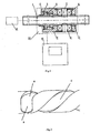
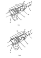
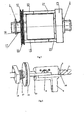
- Fig. 1-6 1- the screw with variable lead angle, 2- nut, 3- retainer ring, 4- torsion spring, 5- pin shaft, 6-rolling bearing, 7- spindle sleeve, 8- bearing cap, 9-nut sleeve, 10-door, 11- power source, 12-pull-wire wheel, 13-left shift lever, 14-right shift lever, 15-right connecting plate, 16-pull-wire, 17-torsion spring, 18-middle strut, 19- self-adaptive nut.
- a powerless helical locking mechanism for door consists of the screw with variable lead angle 1, and self-adaptive nut 19; the screw with variable lead angle 1 is connected with power source 11, the power source can drive the screw with variable lead angle to rotate bidirectionally, and the self-adaptive nut 19 is connected with door 10 as drives the self-adaptive nut 19 and the door to move synchronously.
- the screw slot of the screw with variable lead angle 1 is divided into three sections: working section with the lead angle more than the friction angle, locking section with the lead angle less than the friction angle, and transition section between them; the screw slot of the screw with variable lead angle has rectangle or trapezoid threaded end face, the screw slot of the screw with variable lead angle may be single head or multiple heads;
- the self-adaptive nut 19 consists of spindle sleeve 7, pin shaft 5, nut sleeve 9, nut 2, rolling bearing 6 and bearing cap 8, retainer ring 3, and torsion spring 4;
- the nut 2 and nut sleeve 9 have the circumference rotary connection, and have rigid connection through retainer ring 3 in axis; one end of torsion spring 4 is connected with nut sleeve 9, and the other end is connected with nut 2, the pin shaft and spindle sleeve are connected in rigid connection or rotary connection, when the pin shaft 5 and spindle sleeve 7 are in rigid connection, the
- the screw with variable lead angle 1 makes CW rotation to drive the self-adaptive nut 19 to move from the working section of the screw with variable lead angle to locking section, until the self-adaptive nut 19 enters the locking section and the door is locked.
- the screw with variable lead angle 1 makes CCW rotation to drive the self-adaptive nut 19 to leave the locking section and move reversely to open the door.
- the movement of self-adaptive nut 19 drives the screw with variable lead angle 1 to make CW rotation, let the self-adaptive nut 19 enter the locking section of the screw with variable lead angle to manually close the door and lock the door.
- the manual opening of the door is shown in Fig. 5 .
- the right shift lever 14 is connected with nut 2 of self-adaptive nut 19 through the right connecting plate 15; the left shift lever 13 is connected with pull wire wheel 12; the pull wire wheel 12 is idly set on the screw with variable lead angle 1; pull wire 16 is connected with pull wire wheel 12; one end of torsion spring 17 is connected with pull wire 16 and the other end is connected with middle strut 18.
- the pull wire 16 drives the pull wire wheel 12 and left shift lever 13 to rotate and through the right shift lever 14, the right connecting plate 15 drives the nut 2 to rotate to realize the rotation of the screw with variable lead angle 1 to a specific angle, after the manual unlock is completed, open the door by hands with the CCW rotation of self-adaptive nut 19.
- the pull wire wheel 12 and pull wire 16 reset to be ready for the next manual unlocking.
- Fig.2 is the partial enlargement view of typical section of screw slot of the screw with variable lead angle 1, wherein, part A is the locking section, with the lead angle less than the friction angle, part C is the working section, with the lead angle more than the friction angle, and part B is the transition section between them, with the lead angle varies continuously.
- Fig.3 is the illustration of pin shaft 5 of self-adaptive nut 19 at the working section of the screw with variable lead angle 1, the self-adaptive nut 19 and the screw with variable lead angle 1 are assembled into a screw kinematic pair, the pin shaft of self-adaptive nut 19 is deep into the screw slot of the screw with variable lead angle 1 and is in linear contact with the screw slot, the pin shaft and screw slot with any lead angles can form the matched screw pair to transfer the power and motion, to realize open and close of the door.
- Fig.4 is the illustration of pin shaft of self-adaptive nut 19 at the locking section of the screw with variable lead angle 1, at the locking section of the screw with variable lead angle 1, with the self-locking caused by that lead angle of screw pair is less than the friction angle, the screw slot of locking section in the screw with variable lead angle 1 can lockup the pin shaft 5, that is, the self-adaptive nut 19 is unable to move, thus reliably locks the door.
Landscapes
- Lock And Its Accessories (AREA)
- Transmission Devices (AREA)
- Power-Operated Mechanisms For Wings (AREA)
Claims (3)
- Passiver schraubenförmiger Mechanismus für eine Tür, umfassend:eine Schraube (1) mit einem schraubenförmigen Schraubenschlitz (1') mit einem variablen Steigungswinkel und einer selbst anpassenden Schraubenmutter (19),wobei die Schraube (1) mit variablem Steigungswinkel mit einer Stromquelle (11) verbunden ist, die ausgelegt ist, um die Schraube (1) anzutreiben, um sich bidirektional zu drehen, wobei die selbst anpassende Schraubenmutter (19) mit einer Tür (10) verbunden ist,wobei die selbst anpassende Schraubenmutter (19) eine Pinole (7) und einen Bolzenschaft (5) umfasst, der daran befestigt ist und mit der Schraube (1) zusammengebaut ist, um ein Schraubengelenk zu bilden,wobei sich der Bolzenschaft (5) in der selbst anpassenden Schraubenmutter (19) tief in den Schraubenschlitz (1') der Schraube (1) erstreckt und in linearem Kontakt mit dem Schraubenschlitz (1`) der Schraube (1) steht, undwobei der Bolzenschaft (5) und der Schraubenschlitz (1') ein angepasstes Schraubenpaar bilden, um die Kraft- und die Bewegungsübertragung bei jedem Steigungswinkel durchzuführen,wobei der Schraubenschlitz (1') der Schraube (1) in drei Abschnitte unterteilt ist, d.h. einen Arbeitsabschnitt (C) mit einem Steigungswinkel, der größer als der selbsthemmende Reibwinkel ist, einen Verschlussabschnitt (A) und einen Übergangsabschnitt (B) zwischen dem Arbeitsabschnitt (C) und dem Verschlussabschnitt (A) mit einem ununterbrochen variierenden Steigungswinkel,dadurch gekennzeichnet, dassder Verschlussabschnitt (A) einen Steigungswinkel aufweist, der als der selbsthemmende Reibwinkel ist,der Mechanismus weiter eine manuelle Entriegelungsvorrichtung umfasst,die manuelle Entriegelungsvorrichtung ein Zugseilrad (12) umfasst, einen linken Schalthebel (13), einen rechten Schalthebel (14), eine rechte Verbindungsplatte (15), ein Zugseil (16), eine Torsionsfeder (17) und eine mittlere Strebe (18),der rechte Schalthebel (14) mit einer Schraubenmutter (2) der selbst anpassenden Schraubenmutter (19) durch die rechte Verbindungsplatte (15) verbunden ist,der linke Schalthebel (13) mit dem Zugseilrad (12) verbunden ist,das Zugseilrad (12) leer laufend auf der Schraube mit variablem Steigungswinkel (1) eingestellt ist, das Zugseil (16) mit dem Zugseilrad (12) verbunden ist, undein Ende der Torsionsfeder (17) mit dem Zugseil (16) verbunden ist und das andere Ende mit der mittleren Strebe (18) verbunden ist,wobei das Zugseil (16) ausgelegt ist, um das Zugseilrad (12) und den linken Schalthebel (13) anzutreiben, um sich zu drehen, und durch den rechten Schalthebel (14), ebenso wie durch die rechte Verbindungsplatte (15) die Schraubenmutter (2) anzutreiben, um sich zu drehen, um die Drehung der Schraube (1) mit variablen Steigungswinkeln durchzuführen.
- Passiver schraubenförmiger Mechanismus für eine Tür nach Anspruch 1, wobei der Bolzenschaft (5) und die Pinole (7) starr verbunden sind und sich das Schraubenpaar in Gleitreibung befindet.
- Passiver schraubenförmiger Mechanismus für eine Tür nach Anspruch 1, wobei der Bolzenschaft (5) und die Pinole (7) drehbar verbunden sind, und sich das Schraubenpaar in Rollreibung befindet.
Priority Applications (1)
| Application Number | Priority Date | Filing Date | Title |
|---|---|---|---|
| PL07720322T PL1932985T3 (pl) | 2006-10-18 | 2007-03-05 | Pasywny spiralny mechanizm blokujący do drzwi |
Applications Claiming Priority (2)
| Application Number | Priority Date | Filing Date | Title |
|---|---|---|---|
| CNB2006100968183A CN100348832C (zh) | 2006-10-18 | 2006-10-18 | 无源螺旋门机锁闭机构 |
| PCT/CN2007/000701 WO2008046278A1 (fr) | 2006-10-18 | 2007-03-05 | Mécanisme de verrouillage de porte hélicoïdal sans force |
Publications (3)
| Publication Number | Publication Date |
|---|---|
| EP1932985A1 EP1932985A1 (de) | 2008-06-18 |
| EP1932985A4 EP1932985A4 (de) | 2012-05-16 |
| EP1932985B1 true EP1932985B1 (de) | 2014-12-17 |
Family
ID=38018298
Family Applications (1)
| Application Number | Title | Priority Date | Filing Date |
|---|---|---|---|
| EP07720322.2A Active EP1932985B1 (de) | 2006-10-18 | 2007-03-05 | Passiver schraubenbetriebener türmaschinensperrmechanismus |
Country Status (14)
| Country | Link |
|---|---|
| US (1) | US8291783B2 (de) |
| EP (1) | EP1932985B1 (de) |
| JP (1) | JP5097209B2 (de) |
| KR (1) | KR101125940B1 (de) |
| CN (1) | CN100348832C (de) |
| AU (1) | AU2007312833B2 (de) |
| CA (1) | CA2666865C (de) |
| DK (1) | DK1932985T3 (de) |
| ES (1) | ES2531171T3 (de) |
| MX (1) | MX2009004125A (de) |
| PL (1) | PL1932985T3 (de) |
| PT (1) | PT1932985E (de) |
| RU (1) | RU2408772C1 (de) |
| WO (1) | WO2008046278A1 (de) |
Families Citing this family (15)
| Publication number | Priority date | Publication date | Assignee | Title |
|---|---|---|---|---|
| CN100356088C (zh) * | 2006-10-19 | 2007-12-19 | 南京康尼机电新技术有限公司 | 自适应变导程螺旋传动机构 |
| CN101446153B (zh) * | 2008-12-26 | 2012-05-16 | 南京康尼机电股份有限公司 | 用于无源螺旋门机锁闭机构的解锁装置 |
| CN101942946B (zh) * | 2010-08-16 | 2013-05-29 | 南京康尼机电股份有限公司 | 一种用于轨道车辆门系统螺旋传动的全程锁闭装置 |
| CN102661099A (zh) * | 2012-05-09 | 2012-09-12 | 南京康尼机电股份有限公司 | 一种无源螺旋门机锁闭装置的冗余锁装置 |
| CN103266826A (zh) * | 2013-06-06 | 2013-08-28 | 江苏申阳电梯部件有限公司 | 一种电控电动车门传动锁闭二合为一的装置 |
| CN103726736B (zh) * | 2013-12-20 | 2017-01-18 | 南京康尼机电股份有限公司 | 适用于无源螺旋锁闭机构的滚动销式辅助螺母装置 |
| CN104895442A (zh) * | 2014-03-05 | 2015-09-09 | 林会明 | 滚柱丝杠塞拉门 |
| US10041287B2 (en) * | 2016-08-31 | 2018-08-07 | Westinghouse Air Brake Technologies Corporation | Secondary retention device for transit door |
| US10415681B2 (en) * | 2017-01-06 | 2019-09-17 | Team Industries, Inc. | Linear actuator |
| US10683921B2 (en) * | 2017-03-08 | 2020-06-16 | Thomson Industries, Inc. | Differential lock actuation and control |
| CN109281999B (zh) * | 2018-11-07 | 2023-09-01 | 段沧桑 | 一种综合自锁机构 |
| CN111734931B (zh) * | 2020-07-16 | 2025-04-15 | 中山大山摄影器材有限公司 | 用于摄影器材的电控滑动装置及其锁定组件 |
| CN112160660A (zh) * | 2020-11-05 | 2021-01-01 | 长春工业大学 | 一种用于城轨车辆塞拉门锁闭机构的紧急解锁装置 |
| US12264513B2 (en) | 2020-11-06 | 2025-04-01 | Westinghouse Air Brake Technologies Corporation | Integrated primary lock and isolation lock emergency release mechanism |
| CN114321307B (zh) * | 2022-01-17 | 2024-04-26 | 四川大学 | 一种螺旋传动结构 |
Citations (2)
| Publication number | Priority date | Publication date | Assignee | Title |
|---|---|---|---|---|
| WO1997002441A1 (en) * | 1995-07-05 | 1997-01-23 | Norco, Inc. | Mechanical drive assembly |
| DE102004046545A1 (de) * | 2004-09-20 | 2006-03-30 | Pintsch Bamag Antriebs- Und Verkehrstechnik Gmbh | Linearantrieb |
Family Cites Families (28)
| Publication number | Priority date | Publication date | Assignee | Title |
|---|---|---|---|---|
| FR395097A (fr) * | 1908-10-09 | 1909-02-09 | Frank Scott | Porte s'ouvrant et se fermant automatiquement |
| US2261450A (en) * | 1940-02-26 | 1941-11-04 | Clarence L Pritchett | Wrench |
| US2818743A (en) * | 1954-05-10 | 1958-01-07 | Reeves Instrument Corp | Motion transforming apparatus |
| US3184214A (en) * | 1962-01-18 | 1965-05-18 | Ottis W King | Cam operated valve |
| BE645677A (de) | 1963-06-03 | |||
| DE2924457C2 (de) * | 1979-06-18 | 1987-03-19 | Rathgeber AG, 8000 München | Antrieb zum Betätigen von Türen |
| US4350460A (en) * | 1980-03-21 | 1982-09-21 | Hyster Company | Vibratory compaction system |
| US4760907A (en) * | 1986-09-29 | 1988-08-02 | Sundstrand Corporation | Variable lead differential travel limiting mechanism |
| SU1442622A1 (ru) * | 1987-01-26 | 1988-12-07 | М. Д. Стоиковтие соедин емых элементов. Различные по | Винтовой замок |
| US4914967A (en) * | 1988-12-23 | 1990-04-10 | General Electric Company | Crossover mechanism for guiding a cam follower through a cam track intersection |
| US5195390A (en) * | 1990-06-14 | 1993-03-23 | Hisami Nogaki | Precision linear mechanical drives |
| US5337627A (en) * | 1991-12-27 | 1994-08-16 | Nissei Plastic Industrial Co., Ltd. | Ball screw |
| US5341598A (en) * | 1992-05-08 | 1994-08-30 | Mark Iv Transportation Products Corporation | Power door drive and door support having motor operated locks |
| JPH0614607U (ja) * | 1992-07-24 | 1994-02-25 | 日本トムソン株式会社 | ボールねじ |
| JP2898899B2 (ja) * | 1995-02-14 | 1999-06-02 | 株式会社ナブコ | モータ駆動式液圧アクチュエータ |
| US5622078A (en) * | 1995-08-21 | 1997-04-22 | Mattson; Brad A. | Linear/helix movement support/solar tracker |
| US6009668A (en) * | 1996-01-22 | 2000-01-04 | Westinghouse Air Brake Company | Power door operator having rotary drive and drive operated direct panel lock |
| CZ290598B6 (cs) * | 1997-04-30 | 2002-08-14 | Vladislav Ing. Csc. Poulek | Trubkový motor |
| CN1224107A (zh) | 1998-01-23 | 1999-07-28 | 西屋气刹车公司 | 具有转动驱动件和门板锁定件的动力门自动开关装置 |
| US6282970B1 (en) * | 1998-09-28 | 2001-09-04 | Westinghouse Air Brake Company | Locking drive nut for screw drive systems |
| US6446389B1 (en) * | 2000-04-14 | 2002-09-10 | Westinghouse Air Brake Technologies Corporation | Tandem sliding door operator |
| DE10103090A1 (de) * | 2001-01-24 | 2002-07-25 | Tornado Antriebstech Gmbh | Antriebseinrichtung für Tore |
| CN2523886Y (zh) | 2001-07-01 | 2002-12-04 | 郭云 | 一种起闭锁 |
| CN2517839Y (zh) | 2001-11-15 | 2002-10-23 | 中国船舶重工集团公司第七研究院第七一三研究所 | 水平滑动门门机 |
| DE20302526U1 (de) * | 2003-02-17 | 2004-06-24 | Marantec Antriebs- Und Steuerungstechnik Gmbh & Co. Kg | Spindelantrieb mit Linearbewegung |
| DE10307308B4 (de) * | 2003-02-20 | 2006-11-30 | Siemens Ag | Einrichtung zum linearen Verfahren einer Nutzmasse |
| CN2644617Y (zh) * | 2003-05-14 | 2004-09-29 | 董祥义 | 螺旋式电动开窗装置 |
| CN1480619A (zh) * | 2003-06-25 | 2004-03-10 | 郭维民 | 用于保险柜门的四方向锁栓机构 |
-
2006
- 2006-10-18 CN CNB2006100968183A patent/CN100348832C/zh active Active
-
2007
- 2007-03-05 PT PT07720322T patent/PT1932985E/pt unknown
- 2007-03-05 PL PL07720322T patent/PL1932985T3/pl unknown
- 2007-03-05 EP EP07720322.2A patent/EP1932985B1/de active Active
- 2007-03-05 ES ES07720322T patent/ES2531171T3/es active Active
- 2007-03-05 KR KR1020097009940A patent/KR101125940B1/ko active Active
- 2007-03-05 JP JP2009532669A patent/JP5097209B2/ja active Active
- 2007-03-05 US US12/446,089 patent/US8291783B2/en active Active
- 2007-03-05 MX MX2009004125A patent/MX2009004125A/es active IP Right Grant
- 2007-03-05 DK DK07720322.2T patent/DK1932985T3/en active
- 2007-03-05 WO PCT/CN2007/000701 patent/WO2008046278A1/zh not_active Ceased
- 2007-03-05 CA CA2666865A patent/CA2666865C/en active Active
- 2007-03-05 RU RU2009117806/21A patent/RU2408772C1/ru active
- 2007-03-05 AU AU2007312833A patent/AU2007312833B2/en active Active
Patent Citations (2)
| Publication number | Priority date | Publication date | Assignee | Title |
|---|---|---|---|---|
| WO1997002441A1 (en) * | 1995-07-05 | 1997-01-23 | Norco, Inc. | Mechanical drive assembly |
| DE102004046545A1 (de) * | 2004-09-20 | 2006-03-30 | Pintsch Bamag Antriebs- Und Verkehrstechnik Gmbh | Linearantrieb |
Also Published As
| Publication number | Publication date |
|---|---|
| PL1932985T3 (pl) | 2015-06-30 |
| US8291783B2 (en) | 2012-10-23 |
| CN100348832C (zh) | 2007-11-14 |
| AU2007312833B2 (en) | 2010-07-22 |
| WO2008046278A1 (fr) | 2008-04-24 |
| ES2531171T3 (es) | 2015-03-11 |
| US20100319259A1 (en) | 2010-12-23 |
| KR20090079953A (ko) | 2009-07-22 |
| EP1932985A1 (de) | 2008-06-18 |
| RU2408772C1 (ru) | 2011-01-10 |
| DK1932985T3 (en) | 2015-03-09 |
| KR101125940B1 (ko) | 2012-03-22 |
| MX2009004125A (es) | 2009-06-26 |
| EP1932985A4 (de) | 2012-05-16 |
| JP2010507031A (ja) | 2010-03-04 |
| AU2007312833A1 (en) | 2008-04-24 |
| CA2666865A1 (en) | 2008-04-24 |
| RU2009117806A (ru) | 2010-11-27 |
| CN1948686A (zh) | 2007-04-18 |
| JP5097209B2 (ja) | 2012-12-12 |
| PT1932985E (pt) | 2015-03-02 |
| CA2666865C (en) | 2012-09-04 |
Similar Documents
| Publication | Publication Date | Title |
|---|---|---|
| EP1932985B1 (de) | Passiver schraubenbetriebener türmaschinensperrmechanismus | |
| US20110012380A1 (en) | Motor vehicle door lock | |
| EP3638925B1 (de) | Parksperrenanordnung für einen antriebsstrang eines kraftfahrzeuges und antriebseinheit mit einer solchen parksperrenanordnung | |
| US9982460B2 (en) | Electric lock | |
| EP2473690B9 (de) | Schliesseinrichtung | |
| CN103835575B (zh) | 具有防敲击开启离合器的锁具 | |
| WO2014060531A1 (de) | Türbetätigungsteil mit integrierter kupplung | |
| EP2561164B1 (de) | Schliesszylinderanordnung | |
| US20230228322A1 (en) | Drive unit for motor vehicle applications | |
| EP2803800B1 (de) | Elektrischer Drehaktuator für eine Eingangs- und Ausgangsvorrichtung, insbesondere einer Tür | |
| DE202009009450U1 (de) | Antriebsvorrichtung zum motorischen Bewegen einer Schiebetür | |
| CN219864511U (zh) | 门窗密封锁定轴向可调的双向传动器 | |
| WO2016088542A1 (ja) | 電気錠 | |
| CN209908112U (zh) | 一种离合式门锁 | |
| RU2598113C2 (ru) | Блок безопасности подъёмника | |
| CN215332077U (zh) | 一种新型碳纤维飞机舱门 | |
| US7540207B2 (en) | Device for actuating the doors of vehicles | |
| CN216043102U (zh) | 一种门锁的齿轮式反锁机构 | |
| CN211950088U (zh) | 一种用于车辆自动门的丝杠制动装置 | |
| CN203755814U (zh) | 具有防敲击开启离合器的锁具 | |
| EP1905932B1 (de) | Schiebetür | |
| CN200955317Y (zh) | 无源螺旋门机锁闭机构 | |
| CN212295996U (zh) | 车辆电动门锁 | |
| TWI386322B (zh) | Rotary door opening and closing device | |
| CN109184364A (zh) | 一种门锁定机构 |
Legal Events
| Date | Code | Title | Description |
|---|---|---|---|
| PUAI | Public reference made under article 153(3) epc to a published international application that has entered the european phase |
Free format text: ORIGINAL CODE: 0009012 |
|
| 17P | Request for examination filed |
Effective date: 20080227 |
|
| AK | Designated contracting states |
Kind code of ref document: A1 Designated state(s): AT BE BG CH CY CZ DE DK EE ES FI FR GB GR HU IE IS IT LI LT LU LV MC MT NL PL PT RO SE SI SK TR |
|
| AX | Request for extension of the european patent |
Extension state: AL BA HR MK RS |
|
| DAX | Request for extension of the european patent (deleted) | ||
| RAP1 | Party data changed (applicant data changed or rights of an application transferred) |
Owner name: NANJING KANGNI MECHANICAL & ELECTRICAL CO., LTD. |
|
| REG | Reference to a national code |
Ref country code: DE Ref legal event code: R079 Ref document number: 602007039696 Country of ref document: DE Free format text: PREVIOUS MAIN CLASS: E05B0065000000 Ipc: E05F0015140000 |
|
| A4 | Supplementary search report drawn up and despatched |
Effective date: 20120418 |
|
| RIC1 | Information provided on ipc code assigned before grant |
Ipc: E05F 15/12 20060101ALI20120412BHEP Ipc: E05F 15/14 20060101AFI20120412BHEP |
|
| 17Q | First examination report despatched |
Effective date: 20130426 |
|
| GRAP | Despatch of communication of intention to grant a patent |
Free format text: ORIGINAL CODE: EPIDOSNIGR1 |
|
| INTG | Intention to grant announced |
Effective date: 20141001 |
|
| GRAS | Grant fee paid |
Free format text: ORIGINAL CODE: EPIDOSNIGR3 |
|
| GRAA | (expected) grant |
Free format text: ORIGINAL CODE: 0009210 |
|
| RIN1 | Information on inventor provided before grant (corrected) |
Inventor name: CHEN, BAOGANG Inventor name: GU, YU Inventor name: LIU, WENPING Inventor name: XU, GUANNAN Inventor name: NI, BANGRONG Inventor name: SHI, XIANG |
|
| AK | Designated contracting states |
Kind code of ref document: B1 Designated state(s): AT BE BG CH CY CZ DE DK EE ES FI FR GB GR HU IE IS IT LI LT LU LV MC MT NL PL PT RO SE SI SK TR |
|
| REG | Reference to a national code |
Ref country code: GB Ref legal event code: FG4D |
|
| REG | Reference to a national code |
Ref country code: CH Ref legal event code: EP |
|
| REG | Reference to a national code |
Ref country code: IE Ref legal event code: FG4D |
|
| REG | Reference to a national code |
Ref country code: AT Ref legal event code: REF Ref document number: 702071 Country of ref document: AT Kind code of ref document: T Effective date: 20150115 |
|
| REG | Reference to a national code |
Ref country code: DE Ref legal event code: R079 Ref document number: 602007039696 Country of ref document: DE Free format text: PREVIOUS MAIN CLASS: E05F0015140000 Ipc: E05F0015632000 |
|
| REG | Reference to a national code |
Ref country code: DE Ref legal event code: R096 Ref document number: 602007039696 Country of ref document: DE Effective date: 20150226 |
|
| REG | Reference to a national code |
Ref country code: PT Ref legal event code: SC4A Free format text: AVAILABILITY OF NATIONAL TRANSLATION Effective date: 20150223 |
|
| REG | Reference to a national code |
Ref country code: RO Ref legal event code: EPE |
|
| REG | Reference to a national code |
Ref country code: DK Ref legal event code: T3 Effective date: 20150306 |
|
| REG | Reference to a national code |
Ref country code: ES Ref legal event code: FG2A Ref document number: 2531171 Country of ref document: ES Kind code of ref document: T3 Effective date: 20150311 |
|
| REG | Reference to a national code |
Ref country code: NL Ref legal event code: T3 |
|
| REG | Reference to a national code |
Ref country code: SE Ref legal event code: TRGR |
|
| REG | Reference to a national code |
Ref country code: FR Ref legal event code: PLFP Year of fee payment: 9 |
|
| REG | Reference to a national code |
Ref country code: GR Ref legal event code: EP Ref document number: 20150400465 Country of ref document: GR Effective date: 20150421 |
|
| PG25 | Lapsed in a contracting state [announced via postgrant information from national office to epo] |
Ref country code: LV Free format text: LAPSE BECAUSE OF FAILURE TO SUBMIT A TRANSLATION OF THE DESCRIPTION OR TO PAY THE FEE WITHIN THE PRESCRIBED TIME-LIMIT Effective date: 20141217 |
|
| REG | Reference to a national code |
Ref country code: PL Ref legal event code: T3 |
|
| PG25 | Lapsed in a contracting state [announced via postgrant information from national office to epo] |
Ref country code: EE Free format text: LAPSE BECAUSE OF FAILURE TO SUBMIT A TRANSLATION OF THE DESCRIPTION OR TO PAY THE FEE WITHIN THE PRESCRIBED TIME-LIMIT Effective date: 20141217 Ref country code: SK Free format text: LAPSE BECAUSE OF FAILURE TO SUBMIT A TRANSLATION OF THE DESCRIPTION OR TO PAY THE FEE WITHIN THE PRESCRIBED TIME-LIMIT Effective date: 20141217 |
|
| REG | Reference to a national code |
Ref country code: HU Ref legal event code: AG4A Ref document number: E023600 Country of ref document: HU |
|
| REG | Reference to a national code |
Ref country code: DE Ref legal event code: R097 Ref document number: 602007039696 Country of ref document: DE |
|
| PLBE | No opposition filed within time limit |
Free format text: ORIGINAL CODE: 0009261 |
|
| STAA | Information on the status of an ep patent application or granted ep patent |
Free format text: STATUS: NO OPPOSITION FILED WITHIN TIME LIMIT |
|
| PG25 | Lapsed in a contracting state [announced via postgrant information from national office to epo] |
Ref country code: MC Free format text: LAPSE BECAUSE OF FAILURE TO SUBMIT A TRANSLATION OF THE DESCRIPTION OR TO PAY THE FEE WITHIN THE PRESCRIBED TIME-LIMIT Effective date: 20141217 |
|
| 26N | No opposition filed |
Effective date: 20150918 |
|
| REG | Reference to a national code |
Ref country code: AT Ref legal event code: UEP Ref document number: 702071 Country of ref document: AT Kind code of ref document: T Effective date: 20141217 |
|
| PG25 | Lapsed in a contracting state [announced via postgrant information from national office to epo] |
Ref country code: SI Free format text: LAPSE BECAUSE OF FAILURE TO SUBMIT A TRANSLATION OF THE DESCRIPTION OR TO PAY THE FEE WITHIN THE PRESCRIBED TIME-LIMIT Effective date: 20141217 |
|
| REG | Reference to a national code |
Ref country code: FR Ref legal event code: PLFP Year of fee payment: 10 |
|
| PG25 | Lapsed in a contracting state [announced via postgrant information from national office to epo] |
Ref country code: MT Free format text: LAPSE BECAUSE OF FAILURE TO SUBMIT A TRANSLATION OF THE DESCRIPTION OR TO PAY THE FEE WITHIN THE PRESCRIBED TIME-LIMIT Effective date: 20141217 |
|
| REG | Reference to a national code |
Ref country code: FR Ref legal event code: PLFP Year of fee payment: 11 |
|
| PG25 | Lapsed in a contracting state [announced via postgrant information from national office to epo] |
Ref country code: CY Free format text: LAPSE BECAUSE OF FAILURE TO SUBMIT A TRANSLATION OF THE DESCRIPTION OR TO PAY THE FEE WITHIN THE PRESCRIBED TIME-LIMIT Effective date: 20141217 |
|
| REG | Reference to a national code |
Ref country code: FR Ref legal event code: PLFP Year of fee payment: 12 |
|
| PGFP | Annual fee paid to national office [announced via postgrant information from national office to epo] |
Ref country code: BG Payment date: 20250226 Year of fee payment: 19 |
|
| PGFP | Annual fee paid to national office [announced via postgrant information from national office to epo] |
Ref country code: HU Payment date: 20250228 Year of fee payment: 19 |
|
| PGFP | Annual fee paid to national office [announced via postgrant information from national office to epo] |
Ref country code: ES Payment date: 20250416 Year of fee payment: 19 |
|
| PGFP | Annual fee paid to national office [announced via postgrant information from national office to epo] |
Ref country code: CH Payment date: 20250401 Year of fee payment: 19 |
|
| PGFP | Annual fee paid to national office [announced via postgrant information from national office to epo] |
Ref country code: NL Payment date: 20260123 Year of fee payment: 20 |
|
| REG | Reference to a national code |
Ref country code: CH Ref legal event code: U11 Free format text: ST27 STATUS EVENT CODE: U-0-0-U10-U11 (AS PROVIDED BY THE NATIONAL OFFICE) Effective date: 20260401 |
|
| PGFP | Annual fee paid to national office [announced via postgrant information from national office to epo] |
Ref country code: SE Payment date: 20260123 Year of fee payment: 20 |
|
| PGFP | Annual fee paid to national office [announced via postgrant information from national office to epo] |
Ref country code: GB Payment date: 20260122 Year of fee payment: 20 Ref country code: LT Payment date: 20260123 Year of fee payment: 20 |
|
| PGFP | Annual fee paid to national office [announced via postgrant information from national office to epo] |
Ref country code: DE Payment date: 20260211 Year of fee payment: 20 Ref country code: DK Payment date: 20260123 Year of fee payment: 20 Ref country code: IE Payment date: 20260123 Year of fee payment: 20 |
|
| PGFP | Annual fee paid to national office [announced via postgrant information from national office to epo] |
Ref country code: AT Payment date: 20260319 Year of fee payment: 20 |
|
| PGFP | Annual fee paid to national office [announced via postgrant information from national office to epo] |
Ref country code: LU Payment date: 20260320 Year of fee payment: 20 Ref country code: RO Payment date: 20260225 Year of fee payment: 20 Ref country code: BE Payment date: 20260211 Year of fee payment: 20 Ref country code: FI Payment date: 20260320 Year of fee payment: 20 Ref country code: IT Payment date: 20260206 Year of fee payment: 20 |
|
| PGFP | Annual fee paid to national office [announced via postgrant information from national office to epo] |
Ref country code: FR Payment date: 20260123 Year of fee payment: 20 Ref country code: IS Payment date: 20260328 Year of fee payment: 20 |
|
| PGFP | Annual fee paid to national office [announced via postgrant information from national office to epo] |
Ref country code: TR Payment date: 20260127 Year of fee payment: 20 |
|
| PGFP | Annual fee paid to national office [announced via postgrant information from national office to epo] |
Ref country code: PT Payment date: 20260223 Year of fee payment: 20 Ref country code: CZ Payment date: 20260223 Year of fee payment: 20 |
|
| PGFP | Annual fee paid to national office [announced via postgrant information from national office to epo] |
Ref country code: GR Payment date: 20260319 Year of fee payment: 20 Ref country code: PL Payment date: 20260123 Year of fee payment: 20 |