EP1933055A2 - Disque de frein composé - Google Patents
Disque de frein composé Download PDFInfo
- Publication number
- EP1933055A2 EP1933055A2 EP07018032A EP07018032A EP1933055A2 EP 1933055 A2 EP1933055 A2 EP 1933055A2 EP 07018032 A EP07018032 A EP 07018032A EP 07018032 A EP07018032 A EP 07018032A EP 1933055 A2 EP1933055 A2 EP 1933055A2
- Authority
- EP
- European Patent Office
- Prior art keywords
- brake disc
- brake disk
- ring
- brake
- hub
- Prior art date
- Legal status (The legal status is an assumption and is not a legal conclusion. Google has not performed a legal analysis and makes no representation as to the accuracy of the status listed.)
- Granted
Links
Images


Classifications
-
- F—MECHANICAL ENGINEERING; LIGHTING; HEATING; WEAPONS; BLASTING
- F16—ENGINEERING ELEMENTS AND UNITS; GENERAL MEASURES FOR PRODUCING AND MAINTAINING EFFECTIVE FUNCTIONING OF MACHINES OR INSTALLATIONS; THERMAL INSULATION IN GENERAL
- F16D—COUPLINGS FOR TRANSMITTING ROTATION; CLUTCHES; BRAKES
- F16D65/00—Parts or details
- F16D65/02—Braking members; Mounting thereof
- F16D65/12—Discs; Drums for disc brakes
-
- F—MECHANICAL ENGINEERING; LIGHTING; HEATING; WEAPONS; BLASTING
- F16—ENGINEERING ELEMENTS AND UNITS; GENERAL MEASURES FOR PRODUCING AND MAINTAINING EFFECTIVE FUNCTIONING OF MACHINES OR INSTALLATIONS; THERMAL INSULATION IN GENERAL
- F16D—COUPLINGS FOR TRANSMITTING ROTATION; CLUTCHES; BRAKES
- F16D65/00—Parts or details
- F16D65/02—Braking members; Mounting thereof
- F16D2065/13—Parts or details of discs or drums
- F16D2065/1304—Structure
- F16D2065/1316—Structure radially segmented
-
- F—MECHANICAL ENGINEERING; LIGHTING; HEATING; WEAPONS; BLASTING
- F16—ENGINEERING ELEMENTS AND UNITS; GENERAL MEASURES FOR PRODUCING AND MAINTAINING EFFECTIVE FUNCTIONING OF MACHINES OR INSTALLATIONS; THERMAL INSULATION IN GENERAL
- F16D—COUPLINGS FOR TRANSMITTING ROTATION; CLUTCHES; BRAKES
- F16D65/00—Parts or details
- F16D65/02—Braking members; Mounting thereof
- F16D2065/13—Parts or details of discs or drums
- F16D2065/134—Connection
- F16D2065/1392—Connection elements
-
- F—MECHANICAL ENGINEERING; LIGHTING; HEATING; WEAPONS; BLASTING
- F16—ENGINEERING ELEMENTS AND UNITS; GENERAL MEASURES FOR PRODUCING AND MAINTAINING EFFECTIVE FUNCTIONING OF MACHINES OR INSTALLATIONS; THERMAL INSULATION IN GENERAL
- F16D—COUPLINGS FOR TRANSMITTING ROTATION; CLUTCHES; BRAKES
- F16D2200/00—Materials; Production methods therefor
- F16D2200/0034—Materials; Production methods therefor non-metallic
- F16D2200/0039—Ceramics
Definitions
- the invention relates to a composite brake disc, comprising a brake disc ring and a brake disc hub and fastening means for connecting a brake disc ring with a brake disc hub in a composite brake disc.
- Brake discs are subject to high thermal and mechanical stresses. If the brake disk cup and the brake disk ring are made of materials having different coefficients of thermal expansion, or if a different heat distribution occurs on the brake disk, undesirably high voltages can arise between the brake disk cup and the brake disk ring. These stresses can lead to a wave-shaped deformation of the brake disc ring.
- pins are guided in radial bores on the inner circumference of the brake disk ring and allow a relative movement of the two components in the radial direction. Since the pins protrude radially in all directions from the brake disk hub, disassembly of the brake disk ring after assembly is no longer possible. By this construction, vibrations are transmitted undamped from the brake disk ring on the brake disk chamber to the brake components and axle components, which noise can be caused.
- a connecting element with a head and a sleeve-shaped shaft holds the brake disc ring and brake disc hub together.
- a thread is provided in the head for receiving a bolt penetrating the shank of the connecting element, wherein a slot running in a plane perpendicular to the axis of the sheath further bisects the head area, and the thread only in the area between the slot and the head end facing away from the shank is provided.
- the invention has the object to find a mounting option for a composite brake disc with a brake disc hub and an attached brake disc ring, the different thermal expansion behavior of both components tolerates without sacrificing the strength of the design and without promoting the occurrence of vibrations additional components should be avoided.
- the free radial movement possibility between the friction ring and the brake disk hub is made possible by elongated holes in at least one of the components brake disk ring and brake disk pot, wherein it is preferable to provide slots in the brake disk chamber, especially if it is made of a metallic material.
- the elastic connection and the plurality of damping friction points reduces the deformation of the brake disc and causes the suppression of vibrations, which ultimately lead to improved comfort behavior.
- the brake disc By dividing the brake disc into two separate components, namely the brake disk pot and the friction ring, they can be made of different materials. The reduction of the deformations allows the use of ceramic materials for the brake disc ring.
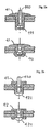
- FIG. 1 a sectional view of an exemplary embodiment of a brake disk 1 with a fastening device 4 according to the invention for brake disk ring 2 and brake disk chamber 3, FIG.
- Fig. 2 Sections through various embodiments of the blind rivets 4 useful according to the present invention , wherein the Fig. 2a shows a cup rivet 41 , the Fig. 2b a Switzerlanddornniet 42, the Fig. 2c a fürziehniet 43, and the Fig. 2d a removable fürziehniet 44.
- the brake disk hub 3 slots 31 for the fastening means wherein the longest extent of the slots 31 is parallel to a passing through the center of the slot 31 radius.
- the length (largest diameter) and the width (smallest diameter) of the oblong holes 31 such that the ratio of the length to the width is at least 2.0, more preferably at least 2.5, and in particular at least 3.0 is.
- the brake disk hub 3 is made of a metallic material.
- FIG. 1 a section through a brake disc 1, in which the attachment of the brake disc ring 2 is shown on the brake disc hub 3 by means of a fürziehniets 43 .
- a cylindrical rivet sleeve 40 is provided in the introduced in the brake disk cup slot 31 , which is not deformed in the fixation of fürziehniets 43 and thereby ensures the radial mobility of the fastener in the slot 31 .
- a washer 21 is provided between rivet head and the brake disk ring 2 .
- the brake disk ring 2 is rotatably connected in the circumferential direction with the brake disk hub 3 , but held radially floating. Axially acting forces between the brake disk cup 3 and brake disk ring 2 are absorbed by the elastic rivet 4 by the elastic connection.
- Fig. 2a to 2d illustrated types of blind rivets are characterized in that they are mounted without impact stress (in contrast to "battered" head rivets).
- the in Fig. 2a illustrated Becherniet 41 also called sealing blind rivet
- FIG. 2c illustrated embodiments in which the mandrel 430 is pulled completely through the interior of the sleeve and this upsets in the sense of a flow forming process under lateral Expansion.
- a removable fürziehniet 44 according to Fig. 2d is a mandrel 440, the tip 441 is designed as an external hex, pulled through the sleeve of the rivet, thereby forming a hexagon socket in the sleeve.
- Such an internally shaped rivet can be removed after installation with the aid of a hexagonal wrench.
- the construction according to the invention with the fastening means provided for it makes it possible to use different materials for brake disk ring and brake disk pot with different thermal expansion coefficients.
- ceramic materials or fiber-reinforced ceramic materials for the brake disc ring are particularly suitable.
- the inventively provided blind rivets as fasteners give a straightforward way a compound that is highly resilient both in the circumferential direction and can be performed without play, as well as a connection with elastic axial play and the possibility of fixation despite different expansion behavior when heated. In the known state of the art, such a simple and economical solution has not yet been described.
Landscapes
- Engineering & Computer Science (AREA)
- General Engineering & Computer Science (AREA)
- Mechanical Engineering (AREA)
- Braking Arrangements (AREA)
Applications Claiming Priority (1)
| Application Number | Priority Date | Filing Date | Title |
|---|---|---|---|
| DE102006058714A DE102006058714A1 (de) | 2006-12-13 | 2006-12-13 | Zusammengesetzte Bremsscheibe |
Publications (3)
| Publication Number | Publication Date |
|---|---|
| EP1933055A2 true EP1933055A2 (fr) | 2008-06-18 |
| EP1933055A3 EP1933055A3 (fr) | 2008-12-31 |
| EP1933055B1 EP1933055B1 (fr) | 2010-11-17 |
Family
ID=39110869
Family Applications (1)
| Application Number | Title | Priority Date | Filing Date |
|---|---|---|---|
| EP07018032A Active EP1933055B1 (fr) | 2006-12-13 | 2007-09-14 | Disque de frein composé |
Country Status (3)
| Country | Link |
|---|---|
| US (1) | US20080164109A1 (fr) |
| EP (1) | EP1933055B1 (fr) |
| DE (2) | DE102006058714A1 (fr) |
Cited By (1)
| Publication number | Priority date | Publication date | Assignee | Title |
|---|---|---|---|---|
| TWI404643B (zh) * | 2012-02-17 | 2013-08-11 | Hui Juan Chen | 固定件及包含該固定件的煞車碟盤 |
Families Citing this family (8)
| Publication number | Priority date | Publication date | Assignee | Title |
|---|---|---|---|---|
| DE102015002572A1 (de) * | 2015-02-27 | 2016-09-01 | Wabco Europe Bvba | Scheibenbremse, insbesondere für Nutzfahrzeuge, und Bremssattel einer solchen Scheibenbremse |
| US10427776B2 (en) * | 2016-07-27 | 2019-10-01 | The Boeing Company | Sliding joint kits, systems containing the same, and related methods |
| DE102017210451A1 (de) * | 2017-04-27 | 2018-10-31 | Robert Bosch Gmbh | Bremsscheibenanordnung für eine Scheibenbremse eines Kraftfahrzeugs, Verfahren |
| DE102018212862A1 (de) * | 2017-08-02 | 2019-02-07 | Robert Bosch Gmbh | Bremsscheibe und Verfahren zur Herstellung einer Bremsscheibe |
| DE102018212864A1 (de) * | 2017-08-02 | 2019-02-07 | Robert Bosch Gmbh | Bremsscheibe und Verfahren zur Herstellung einer Bremsscheibe |
| IT201700097892A1 (it) * | 2017-08-31 | 2019-03-03 | Freni Brembo Spa | Disco freno per freno a disco |
| US20230383804A1 (en) * | 2022-05-27 | 2023-11-30 | Arvinmeritor Technology, Llc | Brake rotor assembly and method of assembly |
| US12449009B2 (en) | 2023-03-06 | 2025-10-21 | Honeywell International Inc. | Brake disc insert assembly |
Family Cites Families (24)
| Publication number | Priority date | Publication date | Assignee | Title |
|---|---|---|---|---|
| US2614946A (en) * | 1950-03-17 | 1952-10-21 | Carborundum Co | Granular silicon carbide and method of making same |
| NL248062A (fr) * | 1959-07-17 | |||
| US3438301A (en) * | 1967-04-10 | 1969-04-15 | Emhart Corp | Hollow rivet and pull-stem assembly for blind fastening or the like |
| GB8315077D0 (en) * | 1983-06-01 | 1983-07-06 | Avdel Ltd | Threaded fastener |
| GB8702155D0 (en) * | 1987-01-30 | 1987-03-04 | Avdel Ltd | Break-stem blind rivet |
| DE3920418A1 (de) * | 1989-06-22 | 1991-01-03 | Schwaebische Huettenwerke Gmbh | Bremsscheibe fuer scheibenbremsen |
| GB2234024B (en) * | 1989-07-22 | 1993-09-29 | Dunlop Ltd | Carbon composite laminated structures |
| GB2269873A (en) * | 1992-08-21 | 1994-02-23 | Avdel Systems Ltd | Self-plugging blind fastener |
| DE4332951A1 (de) * | 1993-01-28 | 1994-08-04 | Schwaebische Huettenwerke Gmbh | Bremsscheibe |
| GB9501849D0 (en) * | 1995-01-31 | 1995-03-22 | Avdel Systems Ltd | Method of fastening members of an assembly |
| EP0872659B1 (fr) * | 1997-04-19 | 2004-09-01 | Dr.Ing.h.c. F. Porsche Aktiengesellschaft | Disque de frein, en particulier à ventilation interne |
| EP0872658A1 (fr) * | 1997-04-19 | 1998-10-21 | Dr.Ing.h.c. F. Porsche Aktiengesellschaft | Disque de frein, en particulier à ventilation interne |
| DE19822579A1 (de) * | 1997-06-12 | 1999-06-10 | Daimler Benz Ag | Bremsscheibe, insbesondere für ein Kraftfahrzeug |
| DE19830669B4 (de) * | 1998-07-09 | 2004-02-05 | Daimlerchrysler Ag | Bremsscheibe, insbesondere für ein Kraftfahrzeug |
| DE19841607C1 (de) * | 1998-09-11 | 2000-03-30 | Porsche Ag | Zweiteilige Bremsscheibe |
| DE19859840B4 (de) * | 1998-12-23 | 2006-01-12 | Daimlerchrysler Ag | Bremseinheit |
| DE19915215A1 (de) * | 1999-04-03 | 2000-10-05 | Bayerische Motoren Werke Ag | Zusammengesetzte Bremsscheibe |
| DE29906138U1 (de) * | 1999-04-09 | 1999-07-01 | Spiegler Bremstechnik GmbH, 79117 Freiburg | Bremsscheibe |
| DE19943537C1 (de) * | 1999-09-11 | 2000-12-21 | Porsche Ag | Verbindungselement für eine Bremsscheibe |
| DE60025300T2 (de) * | 1999-10-18 | 2006-09-21 | Kabushiki Kaisha Yutaka Giken, Hamamatsu | Nietverbindung und Verfahren um zwei Teile mittels Nieten zu verbinden |
| US7198444B2 (en) * | 2002-05-22 | 2007-04-03 | Newfrey Llc | Multi-grip blind rivet |
| DE10262070B4 (de) * | 2002-12-11 | 2007-08-30 | Herbert Alber | Zusammengesetzte Bremsscheibe |
| DE10321796B4 (de) * | 2003-05-14 | 2008-02-14 | Daimler Ag | Bremsscheibe mit Reibring und Bremsscheibentopf |
| DE102004043308A1 (de) * | 2003-09-09 | 2005-05-12 | Continental Teves Ag & Co Ohg | Mehrteilige Bremsscheibe |
-
2006
- 2006-12-13 DE DE102006058714A patent/DE102006058714A1/de not_active Withdrawn
-
2007
- 2007-09-14 EP EP07018032A patent/EP1933055B1/fr active Active
- 2007-09-14 DE DE502007005658T patent/DE502007005658D1/de active Active
- 2007-12-13 US US12/000,502 patent/US20080164109A1/en not_active Abandoned
Cited By (1)
| Publication number | Priority date | Publication date | Assignee | Title |
|---|---|---|---|---|
| TWI404643B (zh) * | 2012-02-17 | 2013-08-11 | Hui Juan Chen | 固定件及包含該固定件的煞車碟盤 |
Also Published As
| Publication number | Publication date |
|---|---|
| DE502007005658D1 (de) | 2010-12-30 |
| EP1933055B1 (fr) | 2010-11-17 |
| EP1933055A3 (fr) | 2008-12-31 |
| DE102006058714A1 (de) | 2008-06-19 |
| US20080164109A1 (en) | 2008-07-10 |
Similar Documents
| Publication | Publication Date | Title |
|---|---|---|
| EP1933055B1 (fr) | Disque de frein composé | |
| EP4204291B1 (fr) | Dispositif de fixation, en particulier pour la fixation d'un entraînement électrique à une bicyclette électrique | |
| EP1238204B1 (fr) | Ensemble disque de frein/moyeu pour freins a disque de vehicule | |
| EP2481942B1 (fr) | Dispositif de serrage pour la fixation d'un arbre creux ou d'un moyeu sur un arbre | |
| AT17467U1 (de) | Fahrzeugrad mit einer Radfelge und einer Radscheibe | |
| EP3615834B1 (fr) | Dispositif de disque de frein prévu pour un frein à disque d'un vehicule, procédé | |
| WO2015158541A1 (fr) | Rotor pourvu d'une bague de support à blocage axial | |
| EP4288670B1 (fr) | Agencement d'entraînement | |
| EP3847383B1 (fr) | Disque de frein composite pour un frein à disque de véhicule | |
| DE10256589B4 (de) | Bremsscheibe für ein Kraftfahrzeug | |
| DE102015217508A1 (de) | Radlageranordnung für eine Fahrzeugachse | |
| DE3320543A1 (de) | Bremsscheibe, insbesondere wellenbremsscheibe fuer schienenfahrzeuge | |
| DE29906138U1 (de) | Bremsscheibe | |
| DE102019125701B4 (de) | Dämpfungsvorrichtung sowie Verfahren zu dessen Montage | |
| DE2315965A1 (de) | Kupplungsscheibe | |
| EP3064705B1 (fr) | Rotor doté d'une tôle de sûreté destiné à protéger un verrouillage rotatif contre le dévissage | |
| DE202012013097U1 (de) | Drehelastische Kupplungsvorrichtung zur Drehmomentübertragung | |
| DE102005059247B4 (de) | Bremsvorrichtung | |
| DE102016211613A1 (de) | Hitzeschildanordnung einer Brennkammer mit Tellerfederpaket | |
| DE10305236A1 (de) | Befestigungseinrichtung zur Verbindung von zwei Teilen einer Bremsscheibe | |
| EP2751439B2 (fr) | Système de freinage d'un frein à tambour | |
| DE102014012554B3 (de) | Baueinheit zum axialen Fixieren von Komponenten auf Wellen und Achsen | |
| EP3825202B1 (fr) | Barre de traction, en particulier pour un accouplement de pare-chocs central d'un véhicule ferroviaire, et écrou destinée au raccordement d'un tirant ancrage d'une barre de traction à un tube de traction de la barre de traction | |
| DE19524926A1 (de) | Elastische Bolzenkupplung | |
| DE102016204839B3 (de) | Mehrteilige Teller-/ oder Hebelfeder mit zwischengeschaltetem Dämpfungselement |
Legal Events
| Date | Code | Title | Description |
|---|---|---|---|
| PUAI | Public reference made under article 153(3) epc to a published international application that has entered the european phase |
Free format text: ORIGINAL CODE: 0009012 |
|
| AK | Designated contracting states |
Kind code of ref document: A2 Designated state(s): AT BE BG CH CY CZ DE DK EE ES FI FR GB GR HU IE IS IT LI LT LU LV MC MT NL PL PT RO SE SI SK TR |
|
| AX | Request for extension of the european patent |
Extension state: AL BA HR MK RS |
|
| PUAL | Search report despatched |
Free format text: ORIGINAL CODE: 0009013 |
|
| AK | Designated contracting states |
Kind code of ref document: A3 Designated state(s): AT BE BG CH CY CZ DE DK EE ES FI FR GB GR HU IE IS IT LI LT LU LV MC MT NL PL PT RO SE SI SK TR |
|
| AX | Request for extension of the european patent |
Extension state: AL BA HR MK RS |
|
| 17P | Request for examination filed |
Effective date: 20090630 |
|
| AKX | Designation fees paid |
Designated state(s): DE FR GB IT |
|
| 17Q | First examination report despatched |
Effective date: 20090819 |
|
| GRAP | Despatch of communication of intention to grant a patent |
Free format text: ORIGINAL CODE: EPIDOSNIGR1 |
|
| GRAS | Grant fee paid |
Free format text: ORIGINAL CODE: EPIDOSNIGR3 |
|
| GRAA | (expected) grant |
Free format text: ORIGINAL CODE: 0009210 |
|
| AK | Designated contracting states |
Kind code of ref document: B1 Designated state(s): DE FR GB IT |
|
| REG | Reference to a national code |
Ref country code: GB Ref legal event code: FG4D Free format text: NOT ENGLISH |
|
| REF | Corresponds to: |
Ref document number: 502007005658 Country of ref document: DE Date of ref document: 20101230 Kind code of ref document: P |
|
| PLBE | No opposition filed within time limit |
Free format text: ORIGINAL CODE: 0009261 |
|
| STAA | Information on the status of an ep patent application or granted ep patent |
Free format text: STATUS: NO OPPOSITION FILED WITHIN TIME LIMIT |
|
| 26N | No opposition filed |
Effective date: 20110818 |
|
| REG | Reference to a national code |
Ref country code: DE Ref legal event code: R097 Ref document number: 502007005658 Country of ref document: DE Effective date: 20110818 |
|
| REG | Reference to a national code |
Ref country code: FR Ref legal event code: PLFP Year of fee payment: 9 |
|
| REG | Reference to a national code |
Ref country code: FR Ref legal event code: PLFP Year of fee payment: 10 |
|
| REG | Reference to a national code |
Ref country code: FR Ref legal event code: PLFP Year of fee payment: 11 |
|
| REG | Reference to a national code |
Ref country code: FR Ref legal event code: PLFP Year of fee payment: 12 |
|
| P01 | Opt-out of the competence of the unified patent court (upc) registered |
Effective date: 20230529 |
|
| PGFP | Annual fee paid to national office [announced via postgrant information from national office to epo] |
Ref country code: DE Payment date: 20250930 Year of fee payment: 19 |
|
| PGFP | Annual fee paid to national office [announced via postgrant information from national office to epo] |
Ref country code: GB Payment date: 20250923 Year of fee payment: 19 |
|
| PGFP | Annual fee paid to national office [announced via postgrant information from national office to epo] |
Ref country code: FR Payment date: 20250925 Year of fee payment: 19 |
|
| PGFP | Annual fee paid to national office [announced via postgrant information from national office to epo] |
Ref country code: IT Payment date: 20250930 Year of fee payment: 19 |