EP1933103B1 - Kälte-/klimatisierungsvorrichtung - Google Patents
Kälte-/klimatisierungsvorrichtung Download PDFInfo
- Publication number
- EP1933103B1 EP1933103B1 EP06746131.9A EP06746131A EP1933103B1 EP 1933103 B1 EP1933103 B1 EP 1933103B1 EP 06746131 A EP06746131 A EP 06746131A EP 1933103 B1 EP1933103 B1 EP 1933103B1
- Authority
- EP
- European Patent Office
- Prior art keywords
- accumulator
- pipeline
- refrigerant
- foreign material
- collecting
- Prior art date
- Legal status (The legal status is an assumption and is not a legal conclusion. Google has not performed a legal analysis and makes no representation as to the accuracy of the status listed.)
- Not-in-force
Links
Images
Classifications
-
- F—MECHANICAL ENGINEERING; LIGHTING; HEATING; WEAPONS; BLASTING
- F25—REFRIGERATION OR COOLING; COMBINED HEATING AND REFRIGERATION SYSTEMS; HEAT PUMP SYSTEMS; MANUFACTURE OR STORAGE OF ICE; LIQUEFACTION SOLIDIFICATION OF GASES
- F25B—REFRIGERATION MACHINES, PLANTS OR SYSTEMS; COMBINED HEATING AND REFRIGERATION SYSTEMS; HEAT PUMP SYSTEMS
- F25B43/00—Arrangements for separating or purifying gases or liquids; Arrangements for vaporising the residuum of liquid refrigerant, e.g. by heat
- F25B43/006—Accumulators
-
- F—MECHANICAL ENGINEERING; LIGHTING; HEATING; WEAPONS; BLASTING
- F25—REFRIGERATION OR COOLING; COMBINED HEATING AND REFRIGERATION SYSTEMS; HEAT PUMP SYSTEMS; MANUFACTURE OR STORAGE OF ICE; LIQUEFACTION SOLIDIFICATION OF GASES
- F25B—REFRIGERATION MACHINES, PLANTS OR SYSTEMS; COMBINED HEATING AND REFRIGERATION SYSTEMS; HEAT PUMP SYSTEMS
- F25B31/00—Compressor arrangements
- F25B31/002—Lubrication
- F25B31/004—Lubrication oil recirculating arrangements
-
- F—MECHANICAL ENGINEERING; LIGHTING; HEATING; WEAPONS; BLASTING
- F25—REFRIGERATION OR COOLING; COMBINED HEATING AND REFRIGERATION SYSTEMS; HEAT PUMP SYSTEMS; MANUFACTURE OR STORAGE OF ICE; LIQUEFACTION SOLIDIFICATION OF GASES
- F25B—REFRIGERATION MACHINES, PLANTS OR SYSTEMS; COMBINED HEATING AND REFRIGERATION SYSTEMS; HEAT PUMP SYSTEMS
- F25B13/00—Compression machines, plants or systems, with reversible cycle
-
- F—MECHANICAL ENGINEERING; LIGHTING; HEATING; WEAPONS; BLASTING
- F25—REFRIGERATION OR COOLING; COMBINED HEATING AND REFRIGERATION SYSTEMS; HEAT PUMP SYSTEMS; MANUFACTURE OR STORAGE OF ICE; LIQUEFACTION SOLIDIFICATION OF GASES
- F25B—REFRIGERATION MACHINES, PLANTS OR SYSTEMS; COMBINED HEATING AND REFRIGERATION SYSTEMS; HEAT PUMP SYSTEMS
- F25B2313/00—Compression machines, plants or systems with reversible cycle not otherwise provided for
- F25B2313/006—Compression machines, plants or systems with reversible cycle not otherwise provided for two pipes connecting the outdoor side to the indoor side with multiple indoor units
-
- F—MECHANICAL ENGINEERING; LIGHTING; HEATING; WEAPONS; BLASTING
- F25—REFRIGERATION OR COOLING; COMBINED HEATING AND REFRIGERATION SYSTEMS; HEAT PUMP SYSTEMS; MANUFACTURE OR STORAGE OF ICE; LIQUEFACTION SOLIDIFICATION OF GASES
- F25B—REFRIGERATION MACHINES, PLANTS OR SYSTEMS; COMBINED HEATING AND REFRIGERATION SYSTEMS; HEAT PUMP SYSTEMS
- F25B2400/00—General features or devices for refrigeration machines, plants or systems, combined heating and refrigeration systems or heat-pump systems, i.e. not limited to a particular subgroup of F25B
- F25B2400/02—Centrifugal separation of gas, liquid or oil
-
- F—MECHANICAL ENGINEERING; LIGHTING; HEATING; WEAPONS; BLASTING
- F25—REFRIGERATION OR COOLING; COMBINED HEATING AND REFRIGERATION SYSTEMS; HEAT PUMP SYSTEMS; MANUFACTURE OR STORAGE OF ICE; LIQUEFACTION SOLIDIFICATION OF GASES
- F25B—REFRIGERATION MACHINES, PLANTS OR SYSTEMS; COMBINED HEATING AND REFRIGERATION SYSTEMS; HEAT PUMP SYSTEMS
- F25B47/00—Arrangements for preventing or removing deposits or corrosion, not provided for in another subclass
Definitions
- the present invention relates to an air-conditioning apparatus constructed by means of connecting a heat-source side unit and a load-side unit using an existing refrigerant pipeline, and particularly, to a technology for separating foreign material mainly including used freezing machine oil as a main component, which is collected from a pipeline by cleaning thereof, and for collecting the same into a collecting container.
- JP 2005-043025 A discloses a refrigerating air conditioner with the heat source side unit including a circuit connected with at least an accumulator, a compressor and a heat source side heat exchanger in order, and a return oil circuit for returning a refrigerator oil from the accumulator to the compressor, the load side unit including the first contraction device and a load side heat exchanger, the first extension piping for connecting the heat source side heat-exchanger to the first contraction device, and the second extension piping for connecting the load side heat exchanger to the compressor.
- the refrigerating air conditioner is further provided with a discharge port provided in the accumulator, and for discharging the foreign matter in the accumulator after a cleaning operation, and an oil returning circuit opening and closing means provided in the oil returning circuit, for opening the oil returning circuit to return the refrigerator oil to the compressor a prescribed amount by a prescribed amount in a usual operation, and for closing the oil returning circuit in the cleaning operation.
- JP 2002-228306 A discloses a refrigeration cycle device, a first refrigerant and a first lubricant oil both of which are formerly used are replaced with a second fresh refrigerant and a second fresh lubricant oil.
- a branching circuit branching from a refrigerant circuit is provided in the refrigerant circuit.
- An oil separating collector for separating and collecting the first lubricant oil from the second refrigerant is provided in the branching circuit, and the branching circuit is closed after performing oil separating/collecting operation at a specified time.
- refrigerating machine oil such as the mineral oil, having been used for CFC (Chloro Floro Carbon) or HCFC (Hydro Chloro Floro Carbon), containing chlorine, before the replacement, is not compatible with new refrigerant HFC series (Hydro Floro Carbon) not containing the chlorine, after the replacement, or the like, and when a great volume of used refrigerating machine oil remains in a refrigerating cycle in the form of residues, the same results in a foreign material (contamination), and there is a possibility that problems such as damaging of the compressor occurs.
- a technology for collecting separated and collected foreign material into a collecting container using an accumulator as a separating device for a refrigerant and the foreign material there is a technology in which a pipeline for degassing a collecting container is connected to an outlet pipe of an accumulator to increase an oil collecting speed, so that an increase of a suction effect by an extent of a pressure loss difference of the pipeline is utilized (for example, refer to the patent documents, 2, 3, and 4).
- Patent Document 1 Japanese Unexamined Patent Application Publication No. 2003-302127 ( Fig. 1, and Fig. 2 )
- Patent Document 2 Japanese Unexamined Patent Application Publication No. 2004-069101 ( Fig. 1 , and Fig. 3 )
- Patent Document 3 Japanese Unexamined Patent Application Publication No. 2004-085037 ( Fig. 1, and Fig. 2 )
- Patent Document 4 Japanese Unexamined Patent Application Publication No. 2004-219016 ( Fig. 1, and Fig. 2 )
- the outlet pipeline of the accumulator is provided two in number, and a motor valve is provided in the middle of the pipeline at a side where the U-shaped pipe and the compressor are connected, and by means of closing the valve at a time of performing a pipeline-cleaning operation, it is prevented that the foreign material returns to the compressor via the hole of the U-shaped pipe even in a case that the large volume of foreign material or a liquid refrigerant returns to the accumulator on start-up or the like.
- a suction pipeline of the compressor including the U-shaped pipe has a large bore diameter ( ⁇ 28.6mm, or the like), and a capacity of a portion lower than the height of the oil return hole is large, and there has been a possibility that a large volume of foreign material such as a volume that cannot be disregarded returns to the compressor.
- the collecting container is installed below the accumulator as a driving force for a collecting operation for the foreign material, and only a head difference thereof is utilized.
- the collecting container is installed below the accumulator as a driving force for a collecting operation for the foreign material, and only a head difference thereof is utilized.
- suction force is weak, it takes great amount of time for a collecting operation, and a construction efficiency becomes bad.
- the viscosity of the oil the viscosity has a tendency to rapidly rise corresponding to the temperature lowering.
- an outlet side of an accumulator (suction side of a compressor) is connected to a degassing pipe of a collecting container so as to increase the suction force for performing a collecting operation for the foreign material. Accordingly, there has been a possibility that a great amount of foreign material in the collecting container overflows and returns to the compressor.
- a float valve, an observation window, or the like is provided so as to prevent the problem, any of them is expensive and there has been a possibility that the mineral oil returns to the compressor while overflowing at a time of a mal-operation of the float valve.
- the collecting container doubles as a container for replenishing oil for a new refrigerant, and is used for replenishing the oil for the new refrigerant that has flowed out in a pipeline-cleaning operation, while previously enclosing the oil for the new refrigerant in the collecting container.
- the present invention is made for solving the problems as described above, and an object is at least to provide a refrigerating air-conditioning apparatus in which firstly, there is no possibility that the foreign material returns to the compressor from the accumulator at a time when a pipeline-cleaning operation is performed, and secondly, it is permitted to collect the foreign material in a short time.
- the aforementioned heat-source side unit includes an accumulator provided with a function for separating and collecting a foreign material in the existing pipeline, and a collecting container for collecting the foreign material separated by means of the aforementioned accumulator, an oil return pipeline for returning the refrigerating machine oil to a compressor via a flowing amount adjusting device is provided below the aforementioned accumulator, wherein at a time of ordinary cooling or heating operation, the refrigerating machine oil is caused to flow into the aforementioned oil return pipeline, and at time of a pipeline-cleaning operation or a foreign material-collecting operation, the aforementioned flowing amount adjusting device is fully closed.
- the heat-source side unit in an air-conditioner in which a heat-source side unit and a load-side unit are connected by means of an existing refrigerant pipeline, the heat-source side unit includes an accumulator for separating and collecting a foreign material in the existing pipeline, and a collecting container for collecting the foreign material separated by means of the accumulator, an oil return pipeline for returning the foreign material to a compressor via a flowing amount adjusting device is provided below the accumulator, wherein at a time of ordinary cooling or heating operation, an oil return circuit is opened, and at a time of a pipeline-cleaning operation or a foreign material-collecting operation, the same is closed.
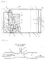
- Fig. 1 is a view showing a refrigerant circuit construction of a refrigerating air-conditioning apparatus according to the first embodiment with respect to the present invention.
- a heat-source side unit 100 is provided with an accumulator 8, a compressor 1, an oil separator 10, a four-way valve 2, a heat-source side heat exchange device 3 and a pressure-adjusting valve 12, and constructs a main circuit of the heat-source side unit 100 by connecting the same in the order.
- the load-side unit 200 is composed of throttling devices, 5a and 5b, and load-side heat exchange devices, 6a and 6b, and the heat-source side unit 100 and the load-side unit 200 are connected by means of an existing liquid-refrigerant pipeline 13, an existing gas refrigerant pipeline 14, and a liquid-side ball valve 4 and a gas-side ball valve 7.
- the heat-source side unit 100 includes a pressure sensor 16 provided at a low pressure portion, and a temperature sensor 17 for measuring a temperature of a position in front of the accumulator 8, at a suction side of the compressor 1.
- a pressure sensor 16 provided at a low pressure portion
- a temperature sensor 17 for measuring a temperature of a position in front of the accumulator 8, at a suction side of the compressor 1.
- the heat-source side unit 100 is provided with an oil tank 11, and at a portion above the oil tank 11, a pipeline in which the refrigerant circuit between a lower portion of the oil separator 10 and a capillary tube for oil return 18a is branched is connected. Another portion above the oil tank 11 is connected to a suction pipeline of the compressor with a pipeline. Moreover, from a portion below the oil tank 11, the oil tank is connected to a pipeline connected between the capillary tube for oil return 18a and the suction pipeline of the compressor via the electromagnetic valve 15b.
- an outlet side of the oil separator 10 and an inlet side of the accumulator 8 are connected via the bypass electromagnetic valve 30, and by means of opening the bypass electromagnetic valve 30, the gas at high temperature and high pressure in the compressor 1 can be introduced to a portion in front of the accumulator 8.
- a connecting portion at the high-pressure side of the bypass circuit is positioned at the outlet side of the oil separator 10 in Fig. 1 , the same may be connected to a portion in front of the oil separator 10.
- the foreign material in the present embodiment mainly refers to used refrigerating machine oil, and hereinafter the foreign material collectively means the used refrigerating machine oil and a residual foreign material in the existing pipeline.
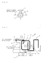
- the foreign material-collecting device 110 is constructed with the accumulator 8, a collecting container 9, a pipeline or a type of valves accompanying the same, and the accumulator 8 functions as a foreign material-separating device, and the accumulated foreign material is collected into the collecting container 9.
- an inlet pipe (accumulator inlet pipe 8a) and an outlet pipe (accumulator outlet pipe 8b) of a main refrigerant circuit are connected thereto.
- An opening portion of the accumulator inlet pipe 8a is positioned at an upper part of the accumulator 8, and an outlet of the pipe is bent so as to face in a horizontal direction of a pipe wall surface so that inflow gas forms a flow along a horizontal direction, or slightly downward direction relative to the horizontal direction of the wall surface.
- An opening portion of the accumulator outlet pipe 8b is positioned at an upper part of the accumulator 8, and is constructed such that the accumulator outlet pipe 8b does not directly suck down liquid unless great amount of the liquid is accumulated in the accumulator 8.
- a collecting pipeline 24a for collecting the foreign material accumulated in the accumulator 8, and an oil return pipeline 24b for returning oil to the compressor 1 at a time of ordinary cooling or heating operations are connected.
- the collecting pipeline 24a is connected to an upper part of the collecting container 9 via a flow amount-adjusting valve 21a and a ball valve 22a.
- the collecting container 9 is provided below the accumulator 8, and a vertical positional relationship between a bottom surface of the accumulator 8 and the collecting container 9 is set such that the bottom surface of the accumulator 8 is configured to be at a position higher than a portion to which the collecting pipe 24a is connected, in an upper end of the collecting container 9.
- the oil return pipeline 24b is connected to a rear suction pipe of accumulator 28 between the accumulator 8 and the compressor 1 via a flow amount-adjusting valve 21b.
- the oil return pipeline 24b is branched into two, and is connected to the rear suction pipe of accumulator 28 at two portions of above and below. The reason is to correspond to a variation of liquid surface height of the accumulator 8. Since the liquid surface is low in an ordinal condition, the oil is returned through a lower connecting pipeline. However, the oil is also returned from a connecting pipeline positioned above when the liquid surface is transiently raised up. Thereby, it becomes possible to correspond to a need for returning the oil to the compressor 1 earlier, by increasing an oil return speed, when great amount of oil is accumulated in the accumulator 8.
- the collecting pipeline 24a and the oil return pipeline 24b are the pipelines for causing the liquid to flow and are formed to be narrower than a main refrigerant pipe.
- the collecting container 9 is installed downwardly in a vertical direction, there is no possibility that the foreign material is accumulated in the pipeline and remains at a main refrigerant circuit side, when the collecting operation for the foreign material is performed.
- a degassing pipe 25 for sucking down the foreign material at the time of collecting operation for the foreign material is provided, and the degassing pipe 25 is connected to a front suction pipe of accumulator 27 via a ball valve 22b and an electromagnetic valve 15c.
- a pressure escape valve 23 is connected in parallel therewith in a manner so as to make a detour for the ball valve 22b and the electromagnetic valve 15c.
- the pressure escape valve 23 has a structure to let out pressure while appropriately opening in a case that an internal pressure of the collecting container 9 rises and it prevents the internal portion of the collecting container 9 from resulting in extraordinary high pressure, and thereby being damaged.
- Fig. 2 is a detailed cross-section of a gas-returning portion of a foreign material-collecting device 110 looking from an axial direction
- Fig. 3 is a detailed cross-section of the gas-returning portion of the foreign material-collecting device 110 looking from a radial direction at a center cross-section of the degassing pipe 25 (sometimes called as gas-returning pipe because the same returns the gas in the collecting container 9 to a low-pressure side main refrigerant circuit).
- the portion to which the degassing pipe 25 of the front suction pipe of accumulator 27 is connected is constructed to have an inner diameter smaller than the inner diameter of the pipeline at the back and forth thereof.
- Bernoulli's theorem (formula 1) as a hydraulic theorem, a total of a pressure head, a velocity head, and a potential head is constant, and when the variation is only that in a horizontal direction as shown in Fig. 2 , the potential head has no variation and can be disregarded.
- p ⁇ g + V 2 2 g + H constant
- the static pressure is defined as, P[Pa]
- the current velocity is defined as, V[m/s]
- the potential head is defined as, H[m]
- the density is defined as, ⁇ [kg/m 3 ]
- the gravitational acceleration is defined as, g[m/s 2 ].
- the mass flow rate is defined as, G[kg/s] and the cross-section area is defined as, A[m 2 ].
- the dynamic pressure rises at the throttled portion, and according to Bernoulli's theorem (formula 1), the pressure head (i.e., static pressure) is lowered by a rising extent of the velocity head (i.e., dynamical pressure).
- the static pressure at a degassing pipe 25 side of the collecting container 9 is lowered and thereby suction force for sucking down to the front suction pipe of accumulator 27 is increased.
- the suction force-increasing effect since a velocity-varying amount by throttling is greater at an area having a large refrigerant circulating amount, namely a current velocity in a pipe than that in the other, the effect outstandingly appears.
- a pressure loss is increased, resulting in lowering of the refrigerant circulating amount when a part of the suction pipeline of a compressor is throttled, a throttling rate of the throttled portion cannot be enormously increased.
- the throttling rate is determined within a range where a bad influence is not applied to a capability.
- a length of a portion, at which the pipeline is throttled is set to be as small as possible, as only in the vicinity of the interflow portion of degassing pipe 26, when a throttling amount is appropriate, (for example, an area ratio of about 60 to 90%), a deterioration of the capability due to the pressure loss does not practically occur.
- the degassing pipe 25 is connected at an angle from the horizontal to a vertical relative to the front suction pipe of accumulator 27, namely at a position higher than the horizontal.
- Fig. 4 is an enlarged view of the foreign material-collecting device 110 composed of the accumulator 8 and the collecting container 9 in Fig. 1 .
- types of valves which do not have direct relationship with an explanation of the principle of the foreign material are omitted in Fig. 4 .
- the head difference from the upper end of the collecting container 9 to a bottom surface of the accumulator 8 is defined as, H[m]
- a static pressure in the interflow portion of degassing pipe 26 is defined as, P1[Pa]
- a static pressure in the accumulator 8 is defined as, P2[Pa]
- a static pressure in the collecting container 9 is defined as, P3[Pa]
- a static pressure at an interflow portion of the oil return pipeline 24b and the rear suction pipe of accumulator 28 is defined as, P4[Pa].
- a current velocity of oil flowing in the collecting pipeline 24a is defined as, V 0 [m/s]
- a pressure loss of the collecting pipeline 24a is defined as, ⁇ [pa].
- a pressure loss of the degassing pipe 25 where only a gas refrigerant having low viscosity, although having the same flowing amount as that of the above described, flows is small as can be relatively disregarded because the flowing amount is small, and therefore is treated as P1 ⁇ P3 here for simplification and is explained.
- the collecting speed for collecting the foreign material is raised by means of a synergistic effect of the aforementioned methods, (1) through (3).
- a construction is formed such that a height position of the upper end of the collecting container 9 is placed to be lower than the bottom surface of the accumulator 8. Further, a further large collecting speed can be obtained by means of maximizing the height position difference as long as a limitation of disposition of a device construction allows.
- a diameter of the pipeline of the collecting pipeline 24a is formed as large as possible, and the length is formed as short as possible.
- the type of intervening valves having as small pressure loss coefficient as possible are selected.
- a suction effect by means of the static pressure difference is increased by means of lowering the static pressure P1( ⁇ P3) by forming the inner diameter of the front suction pipe of accumulator 27 at the interflow portion of degasing pipe 26 to be smaller than that of the back and forth thereof, as in the present embodiment.
- STEP 1 after performing the construction, an operation is started by a start switch (not shown) provided in outdoor equipment or indoor equipment of the unit. At this moment, until a sequence of cleaning operation is completed, even when a remote controller (not shown) for control is erroneously operated, the compressor 1 is held not to be rotated. Further, when the remote controller is operated in a case that the sequence of cleaning operation is not completed, the cleaning operation may be automatically started.
- the compressor 1 is started-up and a cleaning operation 1 is started.
- An operation in a case of operating a cooling cycle will be explained here.
- the gas refrigerant at high temperature and high pressure separates the refrigerating machine oil that is taken out from the compressor 1 in the oil separator 10, and the refrigerant gas is condensed-and-liquefied in the heat-source side heat exchange device 3 via the four-way valve 2.
- the refrigerating machine oil separated in the oil separator 10 flows in the suction pipeline of the compressor 1 via the capillary tube for oil return 18a, and returns to the compressor 1 together with the refrigerant.
- the refrigerant condensed in the heat-source side heat exchange device 3 is brought to be a liquid or a gas-liquid two-phase refrigerant at low dryness.
- the gas-liquid two-phase refrigerant is throttled into medium pressure by means of the pressure-adjusting valve 12.
- the pressure-adjusting valve 12 controls the pressure to be lower than the withstanding pressure of the existing pipeline.
- the gas-liquid two-phase refrigerant at medium pressure or liquid single-phase refrigerant flows through the liquid-refrigerant pipeline 13 and is throttled up to low pressure at throttling devices, 5a and 5b.
- the gas-liquid two-phase refrigerant at low pressure draws heat from the periphery to perform cooling, and the gas-liquid two-phase refrigerant itself evaporates, becomes a gas-refrigerant, and flows in the gas refrigerant pipeline 14.
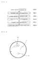
- the refrigerant that has flowed in the gas refrigerant pipeline 14 enters into the accumulator 8 together with a foreign material in the form of a liquid such as mineral oil through the four-way valve 2.
- the refrigerant gas and the foreign material are separated and the refrigerant gas returns to the compressor 1, and the foreign material in the form of a liquid is accumulated in the accumulator 8.
- a structure of the accumulator inlet pipe 8a is constructed such that the refrigerant gas blows out along a horizontal direction of the internal wall of the accumulator. Accordingly, as shown in Fig. 6 , in the accumulator 8, the gas-refrigerant and the foreign material are separated at high efficiency by means of a cyclone effect, in which the foreign material in the form of a liquid collides with a wall surface by means of centrifugal force, and the gas refrigerant and the foreign material are separated.
- the flow amount adjusting valve 21a provided below the accumulator 8, and the electromagnetic valve 15c provided in the degassing pipe 25 are closed, and there is no flow of the foreign material, the refrigerant, or the like toward the collecting container 9, and completely closed.
- the flow amount adjusting valve 21a and the electromagnetic valve 15c are opened only at a time of the collecting operation for the foreign material, and in an operating condition other than the above, the valves are closed.
- the ball valves, 22a and 22b are opened, and this is an initialization at a time of shipping.
- the flow amount adjusting valve 21b for oil return provided at the oil return pipeline 24b is closed from STEP 1 until STEP 5 is completed, and there is no possibility that the foreign material returns to the compressor 1 via the oil return pipeline 24b.
- the aforementioned calculation processing and the control processing are performed by means of a microcomputer (not shown) or the like housed in the heat-source side unit 100.
- the target superheat is, for example, 10 degrees in Celsius, and at least the superheat of the gas refrigerant flowing into the accumulator 8 is configured to be kept in a plus-area.
- the liquid refrigerant is not mixed in the refrigerant flowing into the accumulator 8, and there is no possibility that the liquid refrigerant is accumulated in the accumulator 8.
- the liquid refrigerant When the liquid refrigerant is accumulated in the accumulator 8, the liquid refrigerant is collected together at the time when the foreign material is collected in STEP 5, described later, and thereby an amount of the refrigerant in the refrigerating circuit varies. Therefore, there is a possibility that a bad influence such as lowering of the air-conditioning capability occurs. Accordingly, an operation is required to be configured for the liquid refrigerant not to return into the accumulator 8, in the cleaning operation.
- a construction for evaporating the liquid-refrigerant earlier even in a case when the liquid refrigerant is mixed into inside of the accumulator 8, by means of performing an exterior packaging by wrapping a heater (not shown) around an outer periphery of the accumulator 8, or housing (inner packaging) a heater in the accumulator 8, and turning on the electricity and heating, may be applied.
- the exterior packaging by means of performing the exterior packaging by wrapping a heater (not shown) around the collecting container 9, or housing the heater, the liquid-refrigerant can completely be removed by turning on the electricity and heating the heater, even in a case when the liquid refrigerant is mixed into the collecting container 9.
- the refrigerant required for the main circuit of the refrigerating cycle can assuredly be secured.
- an adjustment for an amount of the refrigerant is performed.
- a refrigerant is added from a refrigerant-filling port, and it is detected that an outlet SC of the condenser and an outlet SH of an evaporator in the refrigerating cycle have reached a predetermined valve.
- STEP 3 is finished and the process proceeds to STEP 4.
- driving operations of the heat-source side unit 100 and the load-side unit 200 is stopped and a time over warning is reported to the outside.
- a proper amount of the refrigerant is judged to be proper when either one of two set criteria of, an amount of the refrigerant necessary for performing an ordinary air-conditioning operation, or an amount of the refrigerant necessary for continuing the cleaning operation, is satisfied.
- the amount of the refrigerant necessary for continuing the cleaning operation is satisfied, the amount of the refrigerant necessary for performing the ordinary air-conditioning operation is not satisfied, the fact that the adjustment for the amount of the refrigerant is required to be again performed is reported to the outside after the sequential cleaning operation is performed.
- a cleaning operation 2 is performed. Although an operating action is approximately the same as that in STEP 2, the compressor 1 may be operated with an operating frequency at a maximum capacity so as to quickly complete the cleaning operation. This operation is performed for a predetermined time, STEP4 is terminated, and collecting operation for the foreign material is performed upon making the shift to STEP 5.
- the flow amount-adjusting valve 21a and the electromagnetic valve 15c being closed in the past STEPs, are opened, and the foreign material accumulated in the accumulator 8 moves to the collecting container 9.
- the collecting speed for collecting the foreign material is raised by means of utilizing the head difference, the suction effect through the degassing pipe 25, and the like, the collecting operation for the foreign material can be completed in a short time.
- the collecting time for the foreign material largely depends on a viscosity of oil as a main component of the foreign material, and can be predicted from the ambient air temperature. By means of setting the collecting time by making an allowance of, for example, 1.5 times or the like, for the predicting time, the foreign material in the accumulator 8 can completely be moved to the collecting container 9.
- the flow amount adjusting valve 21a and the electromagnetic valve 15c are once closed in a condition in which pressure in the collecting container 9 is kept low.
- the bypass electromagnetic valve 30 (in Fig. 1 ) is opened, and thereby the discharge gas at high pressure is introduced to the accumulator 8, resulting in raising the pressure at the accumulator 8 side.
- a pressure difference is generated between the accumulator 8 (high pressure) and the collecting container 9 (low pressure).
- opening the flow amount adjusting valve 21a next it also becomes possible to increase the collecting speed for collecting the foreign material utilizing the generated pressure difference.
- the refrigerant gas and the refrigerating machine oil are separated in the oil tank 11, the refrigerating machine oil is accumulated in the oil tank 11, and the refrigerant gas returns to the suction side of the compressor via the electromagnetic valve 15a.
- the refrigerating air-conditioning apparatus is shipped in a condition of accumulating the refrigerating machine oil in the oil tank 11, and closing the electromagnetic valves, 15a and 15b.
- an amount of oil in the compressor 1 is always properly maintained by means of performing an oil return operation for returning the refrigerating machine oil to the compressor 1 by opening the flow amount adjusting valve 21b in an oil return circuit.
- An opening extent of the flow amount adjusting valve 21b is properly controlled so that an amount of oil corresponding to an operating condition such as an operating frequency of the compressor is returned.
- the oil return circuit is returned to a downstream side of the accumulator 8, a static pressure of the rear suction pipe of accumulator 28 and the oil return pipeline 24b is lower than that in the accumulator 8 due to a pipeline pressure loss as described above, and suction force is generated. Thereby, collecting operation for the oil is brought to be possible.
- an accumulator oil return mechanism in the present embodiment has a construction, in which a hitherto frequently used open-hole type U-shaped pipe is not used, the gas refrigerant is returned from above the accumulator 8, and the oil is returned from the bottom surface of the accumulator 8 via the flow amount adjusting valve 21b. Accordingly, when the flow amount adjusting valve 21b is fully closed, there is no possibility that the oil or the liquid accumulated in the accumulator 8 is returned, and since the flow amount adjusting valve 21b is closed in the above-described STEP 1 through STEP 5, there is no possibility that a disadvantage, in which the foreign material collected in the accumulator 8 returns to the compressor 1, occurs.
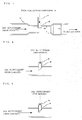
- Fig. 7 is a cross-section showing a part of refrigerant circuit of a refrigerating air-conditioning apparatus according to the second embodiment with respect to the present invention.
- One end of the degassing pipe 25 is connected to the collecting container 9, while the other end thereof is protruded out to an inside of a low-pressure side main refrigerant circuit pipeline (in this example shown in the drawing, a front suction pipe of accumulator 27) from the four-way valve 2 of the heat-source side unit 100 to the suction side of the compressor 1, and connected thereto.
- a low-pressure side main refrigerant circuit pipeline in this example shown in the drawing, a front suction pipe of accumulator 27
- the foreign material moves by means of a pressure difference between the accumulator 8 and the main refrigerant circuit pipeline to which the degassing pipe 25 is connected, and an action of its own weight.
- the refrigerant gas flows and the end portion of the degassing pipe 25 protruded out is exposed to the flow of the gas-refrigerant.
- the present embodiment is the one in which the phenomenon is skillfully utilized. That is, the suction force is increased by means of generating a large static pressure drop around the degassing pipe 25. Thereby, the collecting speed for collecting the foreign material can be increased.
- a diameter of the degassing pipe 25 is small compared to a diameter of the main refrigerant circuit pipeline, and a reduction rate of a flow path cross-section area in the main refrigerant circuit pipeline due to the protruded-out degassing pipe 25 is small. Therefore, an increase of the pressure loss of the gas refrigerant does not practically exist. As a result, lowering of capability due to lowering of a circulating amount of the refrigerant is small.
- An amount of static pressure drop is proportional to dynamical pressure of the flow, namely the square of the current velocity of the gas refrigerant colliding with an end portion of the degassing pipe 25 that is protruded out.
- the flow of the refrigerant gas in the main refrigerant circuit pipeline is in approximately a turbulent flow condition, and in this case, the current velocity in the pipe has a distribution in a radial direction.
- This current velocity distribution is expressed by a distribution that increases, for example, by a distance measured from a pipe wall, to the power of 1/7, and reaches the maximum at an axis of the pipe, namely a so-called law of one-seventh power.
- This distribution is divided into an area in which a distance measured from the pipe wall is 10 to 20% of the radius of the pipe where the current velocity is relatively small and an area other than that where the current velocity is large and relatively uniform. Accordingly, when a tip end of the degassing pipe 25 is protruded out up to the area of the latter, a stable suction force can be obtained. However, since the more the protruding-out length of the degassing pipe 25 increases, the more the reduction rate of the flow path cross-section area in the main refrigerant circuit pipeline increases, particularly, in a case that a diameter of the degassing pipe 25 is relatively large, or the like, the circulating amount of the refrigerant is lowered.
- an optimal position of the tip end of the protruded-out degassing pipe 25 exists in an area between a position, at which a distance measured from the pipe wall in a radial direction is 10 to 20% of the pipe radius, and the axis of the pipe.
- Fig. 8 is a cross-section showing a case in which in the degassing pipe 25, an opening portion of an end portion to be connected to the low-pressure side main refrigerant circuit pipeline is provided with a slanting tip end shape in a manner so as to face the downstream side.
- the opening portion of the protruded-out degassing pipe 25 at a place where the largest static pressure drop can be obtained, which exists between a front face and a back face facing the flow.
- the suction force at the collecting operation for collecting the foreign material from the accumulator 8 to the collecting container 9 can be enlarged by means of constructing the end portion of the degassing pipe 25 to be connected to the main refrigerant pipeline, as in the aforementioned explanation, the collecting speed for the foreign material can be enlarged. As a result, it becomes possible to complete the collecting operation for the foreign material in a short time, and the time required for the process of operation can be reduced. Further, even in a case that the viscosity of the oil as a main component of the foreign material is lowered due to a low outdoor air temperature, it becomes possible to perform the collecting operation in a short time by means of the strong suction force.
Landscapes
- Engineering & Computer Science (AREA)
- Physics & Mathematics (AREA)
- Mechanical Engineering (AREA)
- Thermal Sciences (AREA)
- General Engineering & Computer Science (AREA)
- Chemical & Material Sciences (AREA)
- Analytical Chemistry (AREA)
- Power Engineering (AREA)
- Compressor (AREA)
- Applications Or Details Of Rotary Compressors (AREA)
Claims (11)
- Kühlungs-Klimatisierungsvorrichtung, die durch Verbinden einer wärmequellenseitigen Einheit (100) und einer lastseitigen Einheit (200) mit einer bestehenden Kältemittelleitung (13, 14) konstruiert ist,
wobei die wärmequellenseitige Einheit (100) einen Sammler (8), der mit einer Funktion zum Separieren und Sammeln von Fremdmaterial in einer bestehenden Leitung ausgestattet ist, und einen Sammelbehälter (9) zum Sammeln des Fremdmaterials, das von dem Sammler (8) separiert wird, umfasst und ferner umfasst:eine Ölrückführleitung (24b) zum Zurückführen von Kältemaschinenöl zu einem Kompressor (1) über ein Durchflussmengen-Anpassungsmittel (21b) an einem unteren Bereich des Sammlers (8), undwobei zu einer Zeit eines gewöhnlichen Kühl- oder Heizbetriebs bewirkt wird, dass das Kältemaschinenöl in die Ölrückführleitung (24b) fließt, und zu einer Zeit eines Leitungsreinigungs- und Fremdmaterialsammelbetriebs das Durchflussmengen-Anpassungsmittel (21b) vollständig geschlossen ist,dadurch gekennzeichnet, dassdie Kühlungs-Klimatisierungsvorrichtung ferner Folgendes umfasst:einen niederdruckseitigen Kreislauf, der durch Verbinden eines Vierwegeventils (2), des Sammlers (8) und des Kompressors (1) in der Reihenfolge in einem Inneren der wärmequellenseitigen Einheit (100) konstruiert ist, undeinen niederdruckseitigen Drucksensor (16), der auf einem Weg von dem Vierwegeventil (2) zu dem Kompressor (1) vorgesehen ist,einen Temperatursensor (17), der in der sammlereinlassseitigen Kältemittelleitung vorgesehen ist, undein Mittel zum Berechnen einer Überhitzung eines Kältemittels an der Sammlereinlassseite,wobei die Kühlungs-Klimatisierungsvorrichtung dazu ausgelegt ist, eine Steuerung auszuführen, damit eine Überhitzung an der Sammlereinlassseite in einem Plus-Bereich gehalten wird, und eine Steuerung auszuführen, damit ein flüssiges Kältemittel in dem Sammler (8) verdampft wird. - Kühlungs-Klimatisierungsvorrichtung nach Anspruch 1, wobei ein Einlassrohr (8a) des Sammlers (8) derart installiert ist, dass Kältemittelgas, das in den Sammler (8) strömt, zu einer Strömung wird, die einer horizontalen Richtung einer Seitenwand in dem Sammler (8) folgt.
- Kühlungs-Klimatisierungsvorrichtung nach einem der Ansprüche 1 oder 2, wobei ein Auslassrohr (8b) des Sammlers (8) so ausgebildet ist, dass es eine Struktur aufweist, die sich an einem oberen Teil in einem Inneren des Sammlers (8) öffnet.
- Kühlungs-Klimatisierungsvorrichtung nach einem der Ansprüche 1 bis 3, wobei eine niederdruckseitige Hauptkältemittelkreislaufleitung von dem Vierwegeventil (2) der wärmequellenseitigen Einheit (100) zu einer Kompressoransaugseite und der Sammelbehälter (9) durch ein Entgasungsrohr (25) verbunden sind.
- Kühlungs-Klimatisierungsvorrichtung nach einem der Ansprüche 1 bis 4, wobei ein Ölabscheider (10) an einer Höchdruckseite der wärmequellenseitigen Einheit (100) vorgesehen ist und wobei ein Öltank (11) in einer Mitte einer Leitung zur Ölrückführung, die den Ölabscheider (10) und den Kompressor (1) der wärmequellenseitigen Einheit (100) verbindet, vorgesehen ist.
- Kühlungs-Klimatisierungsvorrichtung nach einem der Ansprüche 1 bis 5, wobei ein Öffnungs- und Schließventil eines elektrischen Betriebstyps in einer Leitung zum Verbinden des Sammelbehälters (9) und einer Komponente der wärmequellenseitigen Einheit (100) vorgesehen ist.
- Kühlungs-Klimatisierungsvorrichtung nach einem der Ansprüche 1 bis 6, wobei ein manuelles Öffnungs- und Schließventil in einer Leitung zum Verbinden des Sammelbehälters (9) und einer Komponente der wärmequellenseitigen Einheit (100) vorgesehen ist.
- Kühlungs-Klimatisierungsvorrichtung nach einem der Ansprüche 6 und 7, wobei ein Druckablassventil (23) in der Leitung zum Verbinden des Sammelbehälters (9) und der Komponente der wärmequellenseitigen Einheit (100) vorgesehen ist.
- Kühlungs-Klimatisierungsvorrichtung nach einem der Ansprüche 1 bis 8, wobei der Sammler (8) oder der Sammelbehälter (9) mit einer Heizung ummantelt oder intern mit dieser ausgestattet ist.
- Kühlungs-Klimatisierungsvorrichtung nach einem der Ansprüche 1 bis 9, wobei ein Umgehungsrohr von einer Hochdruckseite von dem Kompressor (1) zu dem Vierwegeventil (2), zu einem Abschnitt vor dem Sammler (8) oder zu dem Sammler (8) über ein Umgehungsventil (30) vorgesehen ist.
- Kühlungs-Klimatisierungsvorrichtung nach Anspruch 10, wobei das Fremdmaterial durch Erzeugen einer Druckdifferenz zwischen dem Sammelbehälter (9) und dem Sammler (8) mittels des Öffnens und Schließens des Umgehungsventils (30) oder einer Drosselvorrichtung, die in der wärmequellenseitigen Einheit (100) oder der lastseitigen Einheit (200) untergebracht ist, in den Sammelbehälter (9) gesaugt wird.
Priority Applications (1)
| Application Number | Priority Date | Filing Date | Title |
|---|---|---|---|
| EP10016039.9A EP2357432B1 (de) | 2005-10-06 | 2006-05-09 | Kühlende Klimaanlage |
Applications Claiming Priority (2)
| Application Number | Priority Date | Filing Date | Title |
|---|---|---|---|
| JP2005293643A JP4726600B2 (ja) | 2005-10-06 | 2005-10-06 | 冷凍空調装置 |
| PCT/JP2006/309300 WO2007039951A1 (ja) | 2005-10-06 | 2006-05-09 | 冷凍空調装置 |
Related Child Applications (2)
| Application Number | Title | Priority Date | Filing Date |
|---|---|---|---|
| EP10016039.9A Division EP2357432B1 (de) | 2005-10-06 | 2006-05-09 | Kühlende Klimaanlage |
| EP10016039.9A Division-Into EP2357432B1 (de) | 2005-10-06 | 2006-05-09 | Kühlende Klimaanlage |
Publications (3)
| Publication Number | Publication Date |
|---|---|
| EP1933103A1 EP1933103A1 (de) | 2008-06-18 |
| EP1933103A4 EP1933103A4 (de) | 2010-07-07 |
| EP1933103B1 true EP1933103B1 (de) | 2016-11-09 |
Family
ID=37905998
Family Applications (2)
| Application Number | Title | Priority Date | Filing Date |
|---|---|---|---|
| EP06746131.9A Not-in-force EP1933103B1 (de) | 2005-10-06 | 2006-05-09 | Kälte-/klimatisierungsvorrichtung |
| EP10016039.9A Active EP2357432B1 (de) | 2005-10-06 | 2006-05-09 | Kühlende Klimaanlage |
Family Applications After (1)
| Application Number | Title | Priority Date | Filing Date |
|---|---|---|---|
| EP10016039.9A Active EP2357432B1 (de) | 2005-10-06 | 2006-05-09 | Kühlende Klimaanlage |
Country Status (5)
| Country | Link |
|---|---|
| US (3) | US20090133435A1 (de) |
| EP (2) | EP1933103B1 (de) |
| JP (1) | JP4726600B2 (de) |
| ES (2) | ES2607989T3 (de) |
| WO (1) | WO2007039951A1 (de) |
Families Citing this family (28)
| Publication number | Priority date | Publication date | Assignee | Title |
|---|---|---|---|---|
| JP4841494B2 (ja) | 2006-12-11 | 2011-12-21 | 株式会社マルハニチロ水産 | 食品中タンパク質の高感度検出法 |
| JP5063670B2 (ja) * | 2009-12-03 | 2012-10-31 | 三菱電機株式会社 | 空気調和装置、および空気調和装置の洗浄運転方法 |
| JP5609315B2 (ja) * | 2010-06-28 | 2014-10-22 | ダイキン工業株式会社 | 空気調和機 |
| WO2012098582A1 (ja) * | 2011-01-20 | 2012-07-26 | 三菱電機株式会社 | 冷凍サイクル装置 |
| CN103946652B (zh) * | 2011-11-18 | 2016-08-24 | 三洋电机株式会社 | 冷冻装置 |
| JP2013108396A (ja) * | 2011-11-18 | 2013-06-06 | Sanyo Electric Co Ltd | 冷凍装置 |
| EP2674697B1 (de) * | 2012-06-14 | 2018-09-12 | Alfa Laval Corporate AB | Plattenwärmetauscher |
| CN104823007B (zh) * | 2012-11-29 | 2017-08-01 | 江森自控科技公司 | 制冷剂系统的压力控制 |
| JP6184156B2 (ja) * | 2013-04-23 | 2017-08-23 | 三菱電機株式会社 | 冷凍サイクル装置 |
| JP6116684B2 (ja) * | 2013-05-16 | 2017-04-19 | 三菱電機株式会社 | 冷凍装置 |
| JP5999050B2 (ja) * | 2013-08-29 | 2016-09-28 | 株式会社デンソー | エジェクタ式冷凍サイクルおよびエジェクタ |
| US9976783B2 (en) * | 2013-09-24 | 2018-05-22 | Mitsubishi Electric Corporation | Refrigeration cycle apparatus |
| US9857111B2 (en) * | 2013-12-04 | 2018-01-02 | Bosch Automotive Service Solutions Inc. | Method and apparatus for recovering refrigerant from an air conditioning system |
| KR102073011B1 (ko) | 2013-12-18 | 2020-03-02 | 삼성전자주식회사 | 오일 검출 장치, 그를 가지는 압축기 및 압축기의 제어 방법 |
| JPWO2015140878A1 (ja) * | 2014-03-17 | 2017-04-06 | 三菱電機株式会社 | アキュムレータ及び冷凍サイクル装置 |
| US10401047B2 (en) * | 2014-06-27 | 2019-09-03 | Mitsubishi Electric Corporation | Refrigeration cycle apparatus |
| JP6904259B2 (ja) * | 2015-12-21 | 2021-07-14 | 日本電気株式会社 | 冷媒循環装置および冷媒循環方法 |
| US10634389B2 (en) * | 2016-01-14 | 2020-04-28 | Mitsubishi Electric Corporation | Refrigeration cycle apparatus |
| WO2017145826A1 (ja) * | 2016-02-24 | 2017-08-31 | 旭硝子株式会社 | 冷凍サイクル装置 |
| CN105805986A (zh) * | 2016-04-27 | 2016-07-27 | 田幼华 | 一种具有辅助回油的热泵系统 |
| JP6380515B2 (ja) * | 2016-12-05 | 2018-08-29 | 株式会社富士通ゼネラル | 気液分離器およびこれを備えた空気調和装置 |
| CN107939649B (zh) * | 2017-11-10 | 2019-07-26 | 广东美的暖通设备有限公司 | 多联机系统及其压缩机油量调节方法和调节装置 |
| JP7156841B2 (ja) * | 2018-07-11 | 2022-10-19 | 三菱重工サーマルシステムズ株式会社 | アキュムレータ及び冷凍サイクル |
| JP7235451B2 (ja) * | 2018-07-11 | 2023-03-08 | 三菱重工サーマルシステムズ株式会社 | アキュムレータ |
| CN109405102B (zh) * | 2018-10-08 | 2024-01-16 | 珠海格力电器股份有限公司 | 空调系统 |
| CN110715414B (zh) * | 2019-10-16 | 2021-04-20 | 广东美的制冷设备有限公司 | 空调及其控制方法和控制系统 |
| WO2022230101A1 (ja) * | 2021-04-28 | 2022-11-03 | 三菱電機株式会社 | 受液器および冷凍サイクル装置 |
| WO2023199511A1 (ja) * | 2022-04-15 | 2023-10-19 | 三菱電機株式会社 | 冷凍サイクル装置 |
Family Cites Families (39)
| Publication number | Priority date | Publication date | Assignee | Title |
|---|---|---|---|---|
| US1899378A (en) * | 1926-10-20 | 1933-02-28 | Servel Inc | Method of and apparatus for separating a liquid from other liquids |
| GB455177A (en) * | 1935-02-12 | 1936-10-15 | Xavier Bechu | Generators for the production of mixed steam and products of combustion |
| US2975613A (en) * | 1959-01-23 | 1961-03-21 | Gen Motors Corp | Refrigerating apparatus with aspirator in a by-pass |
| US3283532A (en) * | 1965-09-23 | 1966-11-08 | Vilter Manufacturing Corp | Refrigerating apparatus with oil separating means |
| DE2308481A1 (de) * | 1972-02-22 | 1973-08-30 | Sabroe & Co As Thomas Ths | Einrichtung, beispielsweise kuehleinrichtung mit einem kompressor zum ausstossen eines kondensierbaren gases in dessen gaszustand |
| GB1479451A (en) * | 1973-06-18 | 1977-07-13 | Svenska Rotor Maskiner Ab | Meshing screw compressors |
| US4193520A (en) * | 1977-08-31 | 1980-03-18 | Robert Duffield | Device for adding soap to shower water |
| US4249389A (en) * | 1979-03-12 | 1981-02-10 | Thermo King Corporation | Crankcase oil return for a transport refrigeration system providing both heating and cooling |
| US4331001A (en) * | 1981-05-11 | 1982-05-25 | General Motors Corporation | Accumulator-dehydrator assembly for an air conditioning system |
| GB2125937B (en) * | 1982-08-26 | 1986-06-25 | Metal Box Plc | Dispensing volatile liquids |
| US4509340A (en) * | 1983-11-10 | 1985-04-09 | Sealed Power Corporation | Accumulator-dehydrator assembly for an air conditioning system |
| JPH032520U (de) * | 1989-05-26 | 1991-01-11 | ||
| US5161385A (en) * | 1991-03-18 | 1992-11-10 | Schumacher Ernest W | Refrigerant recovery and recycle system with flexible storage bag |
| DE4212367C2 (de) * | 1991-04-15 | 2000-08-03 | Denso Corp | Vorrichtung zur Entfernung von Wasser in einem Kühlsystem |
| JP3161734B2 (ja) * | 1991-12-02 | 2001-04-25 | テクノロジカル リソーシィズ プロプライエタリー リミテッド | 反応装置 |
| KR0152286B1 (ko) * | 1992-10-22 | 1998-11-02 | 윤종용 | 냉난방겸용 공기조화기 및 그 제어방법 |
| US5444987A (en) * | 1993-07-02 | 1995-08-29 | Alsenz; Richard H. | Refrigeration system utilizing a jet enthalpy compressor for elevating the suction line pressure |
| JP3002520U (ja) * | 1994-03-28 | 1994-09-27 | 有限会社中島自動車電装 | フロン回収用オイルセパレータ |
| JPH09152202A (ja) * | 1995-12-01 | 1997-06-10 | Matsushita Refrig Co Ltd | 空気調和機 |
| JP3583266B2 (ja) * | 1997-10-02 | 2004-11-04 | 三菱電機株式会社 | 冷熱サイクル用アキュムレータ |
| US5875640A (en) * | 1997-10-10 | 1999-03-02 | Hill; Herbert L. | Multi-story air conditioning system with oil return means |
| JP2000046420A (ja) * | 1998-07-31 | 2000-02-18 | Zexel Corp | 冷凍サイクル |
| JP2000074506A (ja) * | 1998-08-26 | 2000-03-14 | Hitachi Ltd | 電動機内蔵型圧縮式冷凍機 |
| JP2000179952A (ja) * | 1998-12-09 | 2000-06-30 | Nishiyodo Kuchoki Kk | 冷凍サイクル制御装置 |
| JP3431552B2 (ja) | 1999-10-25 | 2003-07-28 | 三菱電機株式会社 | 冷凍空調装置および冷凍空調装置の更新方法 |
| US6510698B2 (en) * | 1999-05-20 | 2003-01-28 | Mitsubishi Denki Kabushiki Kaisha | Refrigeration system, and method of updating and operating the same |
| JP4298123B2 (ja) * | 2000-03-16 | 2009-07-15 | 三菱電機株式会社 | 冷凍装置 |
| JP4569041B2 (ja) * | 2000-07-06 | 2010-10-27 | 株式会社デンソー | 車両用冷凍サイクル装置 |
| WO2002055965A2 (en) * | 2001-01-12 | 2002-07-18 | Icor International, Inc. | Manifold gauge assembly |
| JP4376470B2 (ja) * | 2001-01-30 | 2009-12-02 | 三菱電機株式会社 | 冷凍サイクル装置およびその運転方法 |
| JP2003156258A (ja) * | 2001-11-20 | 2003-05-30 | Fujitsu General Ltd | 空気調和機 |
| JP4110818B2 (ja) | 2002-04-09 | 2008-07-02 | ダイキン工業株式会社 | 冷凍装置 |
| JP2004069101A (ja) | 2002-08-02 | 2004-03-04 | Yanmar Co Ltd | アキュムレータ、及びそのアキュムレータを備える空調機とその運転方法 |
| JP2004085037A (ja) | 2002-08-26 | 2004-03-18 | Yanmar Co Ltd | 空調機および空調機の運転方法 |
| JP2004097995A (ja) * | 2002-09-11 | 2004-04-02 | Ishikawajima Harima Heavy Ind Co Ltd | 気液分離器 |
| US6662576B1 (en) * | 2002-09-23 | 2003-12-16 | Vai Holdings Llc | Refrigeration system with de-superheating bypass |
| JP2004219016A (ja) | 2003-01-17 | 2004-08-05 | Yanmar Co Ltd | 空気調和システム |
| JP4279080B2 (ja) * | 2003-07-25 | 2009-06-17 | 三菱電機株式会社 | 冷凍空調装置及びその更新方法 |
| KR100564444B1 (ko) * | 2003-10-20 | 2006-03-29 | 엘지전자 주식회사 | 에어컨의 액 냉매 누적 방지 장치 및 방법 |
-
2005
- 2005-10-06 JP JP2005293643A patent/JP4726600B2/ja not_active Expired - Fee Related
-
2006
- 2006-05-09 US US11/922,503 patent/US20090133435A1/en not_active Abandoned
- 2006-05-09 WO PCT/JP2006/309300 patent/WO2007039951A1/ja not_active Ceased
- 2006-05-09 EP EP06746131.9A patent/EP1933103B1/de not_active Not-in-force
- 2006-05-09 ES ES06746131.9T patent/ES2607989T3/es active Active
- 2006-05-09 ES ES10016039T patent/ES2702976T3/es active Active
- 2006-05-09 EP EP10016039.9A patent/EP2357432B1/de active Active
-
2011
- 2011-08-26 US US13/219,346 patent/US8931303B2/en active Active
- 2011-08-26 US US13/219,315 patent/US8783059B2/en active Active
Also Published As
| Publication number | Publication date |
|---|---|
| EP1933103A1 (de) | 2008-06-18 |
| ES2607989T3 (es) | 2017-04-05 |
| EP2357432B1 (de) | 2018-11-14 |
| WO2007039951A1 (ja) | 2007-04-12 |
| US20090133435A1 (en) | 2009-05-28 |
| JP4726600B2 (ja) | 2011-07-20 |
| EP2357432A2 (de) | 2011-08-17 |
| ES2702976T3 (es) | 2019-03-06 |
| US8931303B2 (en) | 2015-01-13 |
| EP1933103A4 (de) | 2010-07-07 |
| JP2007101121A (ja) | 2007-04-19 |
| US20110308272A1 (en) | 2011-12-22 |
| US20110308273A1 (en) | 2011-12-22 |
| EP2357432A3 (de) | 2011-08-24 |
| US8783059B2 (en) | 2014-07-22 |
Similar Documents
| Publication | Publication Date | Title |
|---|---|---|
| EP1933103B1 (de) | Kälte-/klimatisierungsvorrichtung | |
| EP1736721B1 (de) | Kältegerät | |
| CN101680694B (zh) | 空调装置 | |
| EP2511630B1 (de) | Klimaanlage und verfahren zum erkennen der kühlmittelmenge in einer klimaanlage | |
| EP2048458B1 (de) | Klimaanlagenvorrichtung | |
| JP5130910B2 (ja) | 空気調和装置及び冷媒量判定方法 | |
| EP2869002B1 (de) | Klimaanlage und zugehöriges Verfahren zur Steuerung | |
| US5953934A (en) | Refrigerant circulating apparatus and method of assembling a refrigerant circuit | |
| EP3252402B1 (de) | Wärmepumpe | |
| JP2002277078A (ja) | 冷凍サイクル | |
| WO2015056704A1 (ja) | 冷凍サイクル装置 | |
| JP4980459B2 (ja) | 冷凍空調装置 | |
| JP2017142016A (ja) | 空気調和装置 | |
| JP5583134B2 (ja) | 熱源側ユニット及び冷凍空気調和装置 | |
| JP2020085269A (ja) | 冷凍サイクル装置 | |
| JP5983678B2 (ja) | 冷凍装置 | |
| WO2023188950A1 (ja) | 冷凍装置 | |
| MXPA98000237A (en) | Refrigerant circulation apparatus and method for assembling a refrigerating circuit |
Legal Events
| Date | Code | Title | Description |
|---|---|---|---|
| PUAI | Public reference made under article 153(3) epc to a published international application that has entered the european phase |
Free format text: ORIGINAL CODE: 0009012 |
|
| 17P | Request for examination filed |
Effective date: 20071204 |
|
| AK | Designated contracting states |
Kind code of ref document: A1 Designated state(s): DE ES FR GB IT |
|
| RBV | Designated contracting states (corrected) |
Designated state(s): DE ES FR GB IT |
|
| A4 | Supplementary search report drawn up and despatched |
Effective date: 20100607 |
|
| DAX | Request for extension of the european patent (deleted) | ||
| GRAP | Despatch of communication of intention to grant a patent |
Free format text: ORIGINAL CODE: EPIDOSNIGR1 |
|
| INTG | Intention to grant announced |
Effective date: 20160509 |
|
| GRAS | Grant fee paid |
Free format text: ORIGINAL CODE: EPIDOSNIGR3 |
|
| GRAA | (expected) grant |
Free format text: ORIGINAL CODE: 0009210 |
|
| AK | Designated contracting states |
Kind code of ref document: B1 Designated state(s): DE ES FR GB IT |
|
| REG | Reference to a national code |
Ref country code: GB Ref legal event code: FG4D |
|
| REG | Reference to a national code |
Ref country code: DE Ref legal event code: R096 Ref document number: 602006050843 Country of ref document: DE |
|
| REG | Reference to a national code |
Ref country code: ES Ref legal event code: FG2A Ref document number: 2607989 Country of ref document: ES Kind code of ref document: T3 Effective date: 20170405 |
|
| REG | Reference to a national code |
Ref country code: FR Ref legal event code: PLFP Year of fee payment: 12 |
|
| REG | Reference to a national code |
Ref country code: DE Ref legal event code: R097 Ref document number: 602006050843 Country of ref document: DE |
|
| PLBE | No opposition filed within time limit |
Free format text: ORIGINAL CODE: 0009261 |
|
| STAA | Information on the status of an ep patent application or granted ep patent |
Free format text: STATUS: NO OPPOSITION FILED WITHIN TIME LIMIT |
|
| 26N | No opposition filed |
Effective date: 20170810 |
|
| REG | Reference to a national code |
Ref country code: FR Ref legal event code: PLFP Year of fee payment: 13 |
|
| REG | Reference to a national code |
Ref country code: DE Ref legal event code: R084 Ref document number: 602006050843 Country of ref document: DE |
|
| REG | Reference to a national code |
Ref country code: GB Ref legal event code: 746 Effective date: 20190117 |
|
| REG | Reference to a national code |
Ref country code: ES Ref legal event code: GC2A Effective date: 20190416 |
|
| REG | Reference to a national code |
Ref country code: FR Ref legal event code: PLFP Year of fee payment: 18 |
|
| PGFP | Annual fee paid to national office [announced via postgrant information from national office to epo] |
Ref country code: GB Payment date: 20230330 Year of fee payment: 18 |
|
| P01 | Opt-out of the competence of the unified patent court (upc) registered |
Effective date: 20230512 |
|
| PGFP | Annual fee paid to national office [announced via postgrant information from national office to epo] |
Ref country code: IT Payment date: 20230412 Year of fee payment: 18 Ref country code: FR Payment date: 20230411 Year of fee payment: 18 Ref country code: ES Payment date: 20230601 Year of fee payment: 18 Ref country code: DE Payment date: 20230331 Year of fee payment: 18 |
|
| REG | Reference to a national code |
Ref country code: DE Ref legal event code: R119 Ref document number: 602006050843 Country of ref document: DE |
|
| GBPC | Gb: european patent ceased through non-payment of renewal fee |
Effective date: 20240509 |
|
| PG25 | Lapsed in a contracting state [announced via postgrant information from national office to epo] |
Ref country code: DE Free format text: LAPSE BECAUSE OF NON-PAYMENT OF DUE FEES Effective date: 20241203 |
|
| PG25 | Lapsed in a contracting state [announced via postgrant information from national office to epo] |
Ref country code: FR Free format text: LAPSE BECAUSE OF NON-PAYMENT OF DUE FEES Effective date: 20240531 |
|
| PG25 | Lapsed in a contracting state [announced via postgrant information from national office to epo] |
Ref country code: IT Free format text: LAPSE BECAUSE OF NON-PAYMENT OF DUE FEES Effective date: 20240509 Ref country code: GB Free format text: LAPSE BECAUSE OF NON-PAYMENT OF DUE FEES Effective date: 20240509 |
|
| REG | Reference to a national code |
Ref country code: ES Ref legal event code: FD2A Effective date: 20250627 |
|
| PG25 | Lapsed in a contracting state [announced via postgrant information from national office to epo] |
Ref country code: ES Free format text: LAPSE BECAUSE OF NON-PAYMENT OF DUE FEES Effective date: 20240510 |