EP1933104A1 - Procédé et dispositif destinés au conditionnement de produits en vrac pouvant couler et se fluidifier - Google Patents
Procédé et dispositif destinés au conditionnement de produits en vrac pouvant couler et se fluidifier Download PDFInfo
- Publication number
- EP1933104A1 EP1933104A1 EP06025942A EP06025942A EP1933104A1 EP 1933104 A1 EP1933104 A1 EP 1933104A1 EP 06025942 A EP06025942 A EP 06025942A EP 06025942 A EP06025942 A EP 06025942A EP 1933104 A1 EP1933104 A1 EP 1933104A1
- Authority
- EP
- European Patent Office
- Prior art keywords
- bulk material
- gas
- heat transfer
- sectional areas
- process space
- Prior art date
- Legal status (The legal status is an assumption and is not a legal conclusion. Google has not performed a legal analysis and makes no representation as to the accuracy of the status listed.)
- Withdrawn
Links
- 238000000034 method Methods 0.000 title claims abstract description 140
- 230000003750 conditioning effect Effects 0.000 title claims abstract description 23
- 239000007787 solid Substances 0.000 title description 10
- 239000013590 bulk material Substances 0.000 claims abstract description 84
- 239000000463 material Substances 0.000 claims abstract description 16
- 238000007599 discharging Methods 0.000 claims abstract description 4
- 238000012546 transfer Methods 0.000 claims description 59
- 239000002245 particle Substances 0.000 claims description 14
- 238000001816 cooling Methods 0.000 claims description 8
- 230000001143 conditioned effect Effects 0.000 claims description 5
- 238000005243 fluidization Methods 0.000 claims description 5
- 230000003247 decreasing effect Effects 0.000 claims description 4
- 125000006850 spacer group Chemical group 0.000 claims description 3
- 238000011144 upstream manufacturing Methods 0.000 claims description 2
- 238000002347 injection Methods 0.000 claims 1
- 239000007924 injection Substances 0.000 claims 1
- 238000012545 processing Methods 0.000 abstract description 5
- 239000007789 gas Substances 0.000 description 79
- 238000011161 development Methods 0.000 description 4
- 230000018109 developmental process Effects 0.000 description 4
- 238000009826 distribution Methods 0.000 description 4
- 238000004140 cleaning Methods 0.000 description 3
- 238000011109 contamination Methods 0.000 description 3
- 238000006073 displacement reaction Methods 0.000 description 3
- 239000000428 dust Substances 0.000 description 3
- 230000000694 effects Effects 0.000 description 3
- 230000005484 gravity Effects 0.000 description 3
- 239000007788 liquid Substances 0.000 description 3
- 238000013461 design Methods 0.000 description 2
- 238000001035 drying Methods 0.000 description 2
- 235000021552 granulated sugar Nutrition 0.000 description 2
- 238000010438 heat treatment Methods 0.000 description 2
- 238000004886 process control Methods 0.000 description 2
- 238000005299 abrasion Methods 0.000 description 1
- 238000009825 accumulation Methods 0.000 description 1
- 238000005054 agglomeration Methods 0.000 description 1
- 230000002776 aggregation Effects 0.000 description 1
- 238000009530 blood pressure measurement Methods 0.000 description 1
- 238000007664 blowing Methods 0.000 description 1
- 238000010924 continuous production Methods 0.000 description 1
- 230000007547 defect Effects 0.000 description 1
- 230000007613 environmental effect Effects 0.000 description 1
- 239000003337 fertilizer Substances 0.000 description 1
- 230000009969 flowable effect Effects 0.000 description 1
- 239000012530 fluid Substances 0.000 description 1
- 238000000265 homogenisation Methods 0.000 description 1
- 238000004519 manufacturing process Methods 0.000 description 1
- 238000005259 measurement Methods 0.000 description 1
- 238000010327 methods by industry Methods 0.000 description 1
- 238000004806 packaging method and process Methods 0.000 description 1
- 230000000737 periodic effect Effects 0.000 description 1
- 238000003860 storage Methods 0.000 description 1
- 238000009827 uniform distribution Methods 0.000 description 1
Images




Classifications
-
- F—MECHANICAL ENGINEERING; LIGHTING; HEATING; WEAPONS; BLASTING
- F28—HEAT EXCHANGE IN GENERAL
- F28C—HEAT-EXCHANGE APPARATUS, NOT PROVIDED FOR IN ANOTHER SUBCLASS, IN WHICH THE HEAT-EXCHANGE MEDIA COME INTO DIRECT CONTACT WITHOUT CHEMICAL INTERACTION
- F28C3/00—Other direct-contact heat-exchange apparatus
- F28C3/10—Other direct-contact heat-exchange apparatus one heat-exchange medium at least being a fluent solid, e.g. a particulate material
- F28C3/12—Other direct-contact heat-exchange apparatus one heat-exchange medium at least being a fluent solid, e.g. a particulate material the heat-exchange medium being a particulate material and a gas, vapour, or liquid
- F28C3/16—Other direct-contact heat-exchange apparatus one heat-exchange medium at least being a fluent solid, e.g. a particulate material the heat-exchange medium being a particulate material and a gas, vapour, or liquid the particulate material forming a bed, e.g. fluidised, on vibratory sieves
-
- F—MECHANICAL ENGINEERING; LIGHTING; HEATING; WEAPONS; BLASTING
- F26—DRYING
- F26B—DRYING SOLID MATERIALS OR OBJECTS BY REMOVING LIQUID THEREFROM
- F26B17/00—Machines or apparatus for drying materials in loose, plastic, or fluidised form, e.g. granules, staple fibres, with progressive movement
- F26B17/12—Machines or apparatus for drying materials in loose, plastic, or fluidised form, e.g. granules, staple fibres, with progressive movement with movement performed solely by gravity, i.e. the material moving through a substantially vertical drying enclosure, e.g. shaft
- F26B17/16—Machines or apparatus for drying materials in loose, plastic, or fluidised form, e.g. granules, staple fibres, with progressive movement with movement performed solely by gravity, i.e. the material moving through a substantially vertical drying enclosure, e.g. shaft the materials passing down a heated surface, e.g. fluid-heated closed ducts or other heating elements in contact with the moving stack of material
Definitions
- the invention relates to an apparatus and a method for conditioning free-flowing, fluidizable solids according to the preambles of claims 1 and 15.
- Another way to condition granular bulk materials is to bring them in direct contact with heat transfer surfaces. These heat transfer surfaces are flowed through by a heat transfer medium, so that the bulk material remains spatially separated from the heat transfer medium.
- the heat transfer coefficients are low in comparison to a flowing contact with the heat transfer medium, since the contact surface is smaller and limited only to the contact surfaces.
- the permitted temperature difference between the bulk material and the heat transfer surfaces is limited by the product properties of the bulk material.
- the EP 444 338 A1 describes a shaft cooler of the type mentioned.
- a variant of a shaft cooler is from the WO 98/25091 known, in which gravitational bulk material slides along cooling surfaces. The bulk material is pressed downwards by gravity and the overpressure present in the upper part of the cooler, inclined baffles cause the bulk material to be in contact with an inner cooling body, so that cooled bulk material can be removed at atmospheric pressure at the lower outlet.
- the GB 1,299,246 A1 describes a fluidized bed apparatus with juxtaposed, vertically extending chambers in which heat transfer surfaces are arranged. From below, a fluidizing gas is flowed in, so that the bulk material is kept in a fluidized state. By a flow guide, a horizontal transport is ensured by the introduction chamber to the discharge, wherein the discharge is arranged above the inflow floor; without a flow from below no bulk material transport will take place and the apparatus will run full if the supply is not interrupted.
- the heat transfer in such a fluidized bed apparatus with built-in heat transfer surfaces takes place partly via the gas and partly directly on the heat transfer surfaces. The heat transfer rates are high, since the fluidized bed intensifies the heat transfer from the heat transfer surfaces to the gas and the gas in turn reaches the entire surface of the bulk material.
- the US 3,721,107 describes a cooling tower with a fixed distributor bottom and vibrating conveyors for discharging a cooled product. Fluidization of the bulk material does not take place. A similar device is in the US 2,656,007 described.
- the object of the present invention is to provide a device and a method with which, when using a minimum amount of gas for fluidizing the bulk material, a high efficiency of the heat and optionally mass transfer can be achieved and reliable process control can be ensured.
- the apparatus for conditioning flowable, fluidizable bulk materials having a process container having an inlet for supplying the bulk material and an outlet arranged below the inlet for discharging the solids, the process container having a process space arranged below the inlet with at least one heat transfer element arranged therein can be traversed by a gaseous or liquid medium and in which below the heat exchanger or a lower boundary is arranged with openings through which a process gas from below into the process chamber can be introduced, provides a lower boundary, which is an upper level and a lower level which are at least partially displaceable relative to each other and form the free cross-sectional areas of variable size.
- the countercurrent process gas quantity is much smaller compared to conventional fluidized bed plants.
- the bulk material thus passes down through the lower boundary and exits the device through an outlet which is below the actual process space in which the conditioning takes place.
- the free cross-sectional areas thus serve simultaneously for the process gas passage as well as for the solids passage.
- top and bottom are to be understood in the usual meaning with respect to the direction of gravity.
- a development of the invention provides that the lower level of the lower boundary of the process space is completely or partially lowered, so that the lower level or parts or elements thereof seen from the upper level is beyond the bulk material or lie.
- the free cross-sectional areas through which both the process gas and the bulk material pass through, can be changed in size.
- the free cross-sectional areas are increased.
- the plane is raised.
- the upper level is preferably arranged rigidly at the lower boundary of the process space in order to ensure the easiest possible assignment of the levels to one another.
- both levels are movably displaced in the region of the lower boundary of the process space and can be changed by a corresponding actuation in position.
- the planes may be tiltable or rotatable relative to each other. A displacement of the planes to each other can be done manually or by motor, in particular pneumatically. If one of the levels consists of several components or elements, these can be designed to be movable individually or in groups so as to provide different cross sections of the free cross-sectional areas distributed over the area of the lower boundary of the process space.
- the upper level of roof-shaped elements in particular elongated profiles are formed, which are arranged spaced from each other.
- the roof-shaped configuration of the profiles prevents an accumulation of bulk particles on the surface of the upper level, since the particles or solid particles slide down along the inclined surfaces. Furthermore, the roof-shaped profile arrangement increases the stability of the elements in the upper level.
- the lower level may also be formed of roof-shaped elements, preferably with a flat roof angle.
- the arranged below the upper level roof-shaped elements are dimensioned so that they cover the spaces between the elements of the upper level seen in the flow direction, that are offset from the profiles or elements of the upper level.
- an overall closed lower boundary of the process space is formed in the projection, the free cross-sectional areas for flowing through or passing through process gas and bulk material are formed by a distance of the elements from one another, so that the process gas flow and the bulk material flow undergo a directional deflection.
- the lower boundary of the process space may be completely closed or for the planes to be arranged relative to one another in such a way that there is a minimal gap or a minimum free cross-sectional area through which the process gas can flow, but the bulk material can not pass due to the particle size or the angle of repose.
- the roof-shaped or otherwise formed lower-level elements may be individually, in groups or jointly displaced relative to the upper level, in particular lowered or raised in order to achieve the desired effects within the process space.
- the individual elements or profiles can each be coupled to an actuator by which a single control is possible.
- a further embodiment provides that a plurality of heat exchanger elements are arranged one above the other, which are flowed through separately by a heat transfer medium.
- the heat transfer elements which may also be arranged in packages of heat transfer elements, are arranged in particular perpendicular to the gas flow direction, ie predominantly horizontally, and consist of a plurality of juxtaposed and superimposed, fluid-flowed tubular body or tube body sections of a heat transfer element.
- the heat transfer elements are formed as a plurality of individual tubular body or as a meander-like bent tube, or the one of a Heat transfer medium, such as gas or liquid, is flowed through.
- the individual heat exchanger elements are formed horizontally spaced from each other to allow bulk material and process gas to pass from top to bottom and vice versa through the process space. If a plurality of layers of heat transfer elements are arranged one above the other, then they are preferably offset relative to one another so that the heat transfer elements of the lower level are below the interstices of the heat transfer elements of the next higher level. Individual heat exchanger elements can be combined to form packages of heat exchanger elements.
- the arrangement of the heat transfer elements or tubular body within the process chamber, the gas flow and the flow behavior of the fluidized bulk material is made uniform, so that especially in fine-grained bulk solids blistering and eruptive passage of the process gas through the packed layer is avoided.
- the vertical arrangement of the heat exchanger elements or packages allows a space-saving design, which has a small footprint and is limited only by the height.
- a development of the invention provides that at the upper end of the process chamber, a return line for the process gas is arranged, which returns the process gas to a fan or compressor.
- a return line for the process gas is arranged, which returns the process gas to a fan or compressor.
- different devices can be used, in particular rotary blower or centrifugal fans are provided. Due to the self-cleaning capability of the device, it is also possible to use a non-dedusted process gas.
- a conditioning unit for the process gas is connected upstream of the fan or compressor, so that the process gas is cleaned, dehumidified or optionally dedusted. The conditioning unit can adapt the process gas to the desired conditioning properties of the bulk material.
- a discharge lock is arranged, through which the bulk material passed through the process space is removed.
- the Discharge lock ensures a pressure seal, so that within the process chamber a controllable process pressure prevails.
- the lower boundary of the process chamber is designed so that the angle of repose of the solids is prevented from exiting at closed levels or even at minimally spaced levels. If the distance is increased or the free cross-sectional areas are increased, it is possible to ensure a bulk material transport even without process gas or recycle gas, since the particles of the bulk material pass through the process space gravitationally driven. Thus, a discharge of the bulk material in case of failure of the fan is possible, so that the conditioning process does not have to be interrupted even with a defect or at least can be stopped controlled.
- the inventive method for conditioning, in particular cooling free-flowing, fluidizable bulk materials in a process space in which introduced from above the bulk material and discharged below a lower boundary of the process chamber via an outlet, provides that the lower boundary of the process chamber has free cross-sectional areas, the used simultaneously for the discharge of the bulk material down and the supply of process gas in countercurrent upward into the process space, wherein the free cross-sectional areas within the lower limit depending on a process variable, in particular a measured pressure or a level within the process space increased or be downsized.
- the flow rate of the bulk material is controlled by preferably periodically opening or closing or increasing or decreasing the free cross-sectional areas within the lower boundary, with the aim of keeping the pressure within the packed bed or fluidized bed or level constant and a smooth process with uniform results to obtain.
- the pressure within the fluidized bed is proportional to the amount of bulk material in the fluidized bed.
- periodic opening and closing or increasing or decreasing the openings within the lower boundary of the process space is a uniform distribution of Dwell time of the bulk material in the device achieved, so that a uniform Konditionier65 while ensuring a secure process is possible.
- the pressure loss of the lower boundary which may consist of a fixed plane with roof-shaped profiles, between which there is a distance, is very low because of the relatively low gas velocities.
- the gas distribution takes place primarily via the bulk material movement, through which the gas flow is deflected uniformly and distributed over the entire cross-sectional area of the process space.
- the process gas is preferably injected into the bulk material at a relatively low velocity, which is between the vortex point velocity of the bulk material and half the Einzelkornsink technically the mean particle diameter of the bulk material, so that there is a whirling movement within the process space.
- a relatively low velocity which is between the vortex point velocity of the bulk material and half the Einzelkornsink technically the mean particle diameter of the bulk material, so that there is a whirling movement within the process space.
- fluidized bulk particles deflected downward by impulse exchange are moved in the direction of the outlet.
- the process gas can be conducted as cycle gas, whereby an environmental impact is avoided or reduced, wherein the process gas can be conditioned before blowing into the packed bed.
- conditioning is meant in particular the cleaning, cooling or heating or dehumidifying.
- conditioned fresh gas can be supplied to the cycle gas.
- the control of the enlargement or reduction of the free cross-sectional areas via a parameter measurement, in particular level or pressure measurement within the process space. If a predetermined pressure or a certain level is reached or exceeded, the openings are enlarged. The duration and the interval times of the opening depend on the desired throughput.
- a certain pressure value is measured, for example, when the bulk material has reached the upper end of the heat transfer element or the packages of heat transfer elements. If this is the case, the free cross-sectional areas are increased, for example by lowering the lower element level or parts thereof. If the predetermined pressure or level falls below, the cross sections are reduced again until the predetermined pressure value or level value is reached again.
- the conditioning process can be carried out both continuously and batchwise, with an internal dedusting is possible because only small amounts of air for conditioning the bulk material are needed.
- FIG. 1 shows a schematic representation of a fluidized bed system 10 for conditioning fluidizable, free-flowing bulk materials, such as granulated sugar, fertilizer or the like.
- the device 10 has an inlet 11 for product delivery.
- the inlet 11 is arranged at the upper end of the system 10.
- a process space 12 is formed, in which the bulk material is fluidized.
- an outlet 13 for the product outlet in the conditioned state is provided below the process space 12, an outlet 13 for the product outlet in the conditioned state is provided below the outlet 13 a discharge lock 14 is provided, which is driven by a motor and ensures a product discharge under pressure.
- packages 15, 16, 17 of heat exchanger elements 171 are arranged, in which the heat transfer elements 171 are present in the form of tubular bodies, which are flowed through by a heat transfer medium, for example, cooled or heated liquid or cooled or heated gas.
- a heat transfer medium for example, cooled or heated liquid or cooled or heated gas.
- the packages 15, 16, 17 are supplied by the heat transfer medium via a supply line 21 with the heat transfer medium.
- the heat transfer medium passes through all packages 15, 16, 17 of heat transfer elements from bottom to top and is then passed via a return line 22 to a kind of cooling or heating station.
- all packages 15, 16, 17 of heat exchanger elements 171 can be supplied separately with a heat transfer medium.
- cooled fluid is introduced through the supply line 21 into the packages 15, 16, 17 of heat transfer elements.
- process gas is introduced into the process space through the lower boundary 50 at a recycle gas inlet point 181.
- the process gas is, like the heat transfer medium, also passed in countercurrent through the process chamber 12 and simultaneously cools or dries the bulk material, such as granulated sugar.
- the heat exchanger elements 171 within the packages 15, 16, 17 of heat exchanger elements additionally ensure a homogenization of the air flow within the process chamber 12 as well as an avoidance of blistering, which occurs or can occur especially in fine-grained bulk solids.
- a return line 18 is arranged at a process gas outlet 182, so that the recycle gas can be returned to the fan 20. If exhaust gases occur, they are discharged through a drain 180 from the process. Within the return line 18, a conditioning or conditioning unit for the process gas can be switched on.
- fresh process gas 19 is introduced into the return line 18.
- a load cell 40 measures the pressure and other parameters of the fresh gas.
- a pressure measuring unit 30 measures the pressure in the region of the lower limit 50 at the lower end of the process space. If a critical value is reached, an actuator 60 is put into operation via an integrated control unit, which increases or reduces the free cross-sectional areas 55 within the lower limit 50, by lowering or raising the levels 51, 52, not shown, of the lower boundary 50. This serves to control the product pass. In this case, the openings within the lower boundary 50 are not completely closed, so that process gas can pass through, but the passage cross-section is chosen so that the bulk material can not fall through. If a certain level within the process chamber 12 is reached, the pressure loss within the process chamber 12 due to the bulk material therein is so great that the pressure measuring unit 30 determines a corresponding value and then increases the free passage cross-sections. As a result, the bulk material moves through the free cross-sectional areas 55 within the lower boundary 50 and is conveyed through the discharge lock 14 to the outlet and transported away therefrom.
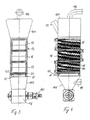
- FIG. 2 is an exploded perspective view.
- the device 10 is partially shown and shows an upper part 101 and a lower part 102 with an inlet 11 and an outlet 13.
- the process gas is introduced through the process gas inlet 181, which is arranged on the lower part 102 and discharged through the process gas outlet 182 on the upper part 101 .
- a package 17 of heat exchanger elements with a plurality of tubular, each other vertically and horizontally offset heat transfer elements 171 is arranged between the upper part 101 and the lower part 102.
- a feed line 21 and a return line 22 provide for the supply and removal of the heat transfer medium, which is passed in countercurrent, ie from bottom to top through the package 17 of heat transfer elements.
- the process space 12 Shooting sidewalls are not shown for clarity.
- a lower boundary 50 which consists of two levels 51, 52. These levels are formed by roof-shaped profiles 1, 2, whose arrangement in FIG. 5 is shown and will be discussed later.
- the two levels 51, 52 are mutually displaceable, in the present embodiment, the lower level 51 can be lowered down, while the upper level 52 is fixed.
- the upper level 52 consists of roof-shaped, spaced-apart longitudinal profiles 2. This prevents that the bulk material remains lying on the profiles 1, 2.
- FIGS. 3 and 4 which show a section of various orientations along the vertical axis of the device 10, it can be seen that the packages 15, 16, 17 of heat transfer elements 171 have separate supply ports and discharge ports.
- the plurality of heat exchanger elements 171 which are arranged substantially horizontally and are arranged transversely to the flow direction of the process gas and to the passage direction of the bulk material, can be recognized.
- the bulk material comes into intensive contact with both the heat transfer elements 171 and with the process gas.
- the bulk material is swirled in countercurrent;
- a heat transfer and optionally a mass transfer is carried out so that the bulk material is dehumidified or moistened.
- FIGS. 3 and 4 to recognize the roof-shaped embodiments of the lower level 51 and the upper level 52 with a steeper roof-shaped structure.
- pneumatic actuators 60 are arranged, which can be lowered to increase the flow cross-section or the free cross-sectional areas 55 within the lower boundary 50.
- the lower level 51 of the profiles is lowered, the gap between the profiles of the lower level 51 and the upper level 52 is increased and a larger flow of bulk material is passed through.
- the structure of the levels 51, 52 and the lower limit 50 is in the FIG. 5 in which a detail of the lower limit 50 is shown.
- the upper level 52 is formed by a plurality of parallel, roof-shaped profiles 2, which are arranged spaced from each other. These profiles 2 are preferably fixedly arranged on the lower boundary of the process space 12. Alternatively, these profiles 2 can be designed to be movable.
- the lower level 51 is arranged with a plurality of slightly roof-shaped profiles 1, which are held by a rail 3 at a fixed distance from each other. The distances can be adjustable. Below this rail 3, the actuators 60 are arranged in the FIG. 5 are not shown.
- the respective profiles 1, 2 are offset from each other and spaced apart within the plane 51, 52, so that the free spaces formed between the respective profiles 1, 2 in the respective plane 51, 52 are covered by the underlying or overlying plane.
- the angle of the roof-shaped profiles 1 is chosen so that no bulk material remains on the surface.
- Between the planes 51, 52 may be provided a permanent distance a, for example, ensured by spacer elements, so that always a minimum amount of process gas can flow through the lower boundary 50 therethrough.
- the distance a is chosen so that the bulk material can not pass through the flow opening, which is formed by the spacing of the two planes 51, 52 to each other.
- the lower level 51 is lowered via a control device 30 and the flow cross section and the passage cross section between the levels 51, 52 enlarged.
- the passage rate is increased if a continuous process takes place, or allows the bulk material to escape during batchwise process control.
- the entire product, including any resulting dusts, is passed through the free cross-sectional areas 55 transported and falls down into the funnel-shaped lower part 102.
- the product passing through eliminates any existing contamination in the free cross-sectional areas 55 due to the abrasive effects of the bulk material.
- the inflow velocity of the process gas in the process chamber 12 is below the speed at which the bulk material would be discharged upward, preferably at a value between the vortex point speed and the half of Einzelkornsink Malawi a bulk material grain with average particle diameter.
- tilting of the levels 51, 52 relative to each other can take place in order to change the size of the free cross-sectional areas 55. It is also possible, in an alternative embodiment, to change the free cross-sectional areas 55 by a displacement in the horizontal plane in order to discharge the bulk material through the lower boundary 50 from the process space 12.
- a displacement in the horizontal plane in order to discharge the bulk material through the lower boundary 50 from the process space 12.
- pyramidal elements may be provided as upper or lower level.
- the amount of fresh gas is such that the optionally desired mass transfer, z. B. drying, is possible.
- the feeding of the bulk material takes place in the upper part 101 of the device 10, which is preferably under a slight negative pressure. If an internal dedusting be provided, a dedusting device, such as a cyclone, also within the upper part 101, which is designed as a hood arranged.
- the free cross-sectional areas 55 clean themselves so that dust-containing gas can be supplied to the fluidized bed without the free cross-sectional areas 55 becoming clogged.
- the cross section is chosen so that the angle of repose of the bulk material prevents leakage of the bulk material.
- the size of the free cross-sectional areas 55 can be adapted to the grain size of the respective product.
- FIG. 6 which has an enlarged section of the FIG. 3 represents, the arrangement of the individual profiles 1, 2 can be seen in the respective planes 51, 52.
- the lower level 51 of the profiles 1 is mounted on a common rail 3 and can be changed via the actuator 60, in this case a pneumatic cylinder, in the vertical position. This is indicated by the double arrow.
- the actuator 60 in this case a pneumatic cylinder, in the vertical position.
- the likewise elongated free cross-sectional areas 55 are formed through which both the process gas flow from bottom to top and the bulk material can pass from top to bottom.
- a package 17 of heat exchanger elements 171 with a plurality of heat exchanger elements 171 is shown above the lower boundary 50.
- the individual heat exchanger elements 171 are arranged substantially horizontally and can extend parallel to one another and offset relative to one another, alternatively or additionally, the heat exchanger elements 171 can also be arranged so as to be oriented horizontally in a horizontal orientation.
- each element 1 or profile 1 can be individually couple with an actuator 60 to lower or raise these individually or in groups.
- the planes 51, 52 can be rotated, shifted or tilted relative to each other. It is also possible to move the individual elements or profiles 1, 2 to each other, to twist or tilt, to cause changes in the free cross-sectional areas 55 to the desired extent.
Landscapes
- Engineering & Computer Science (AREA)
- Mechanical Engineering (AREA)
- General Engineering & Computer Science (AREA)
- Drying Of Solid Materials (AREA)
Priority Applications (1)
| Application Number | Priority Date | Filing Date | Title |
|---|---|---|---|
| EP06025942A EP1933104A1 (fr) | 2006-12-14 | 2006-12-14 | Procédé et dispositif destinés au conditionnement de produits en vrac pouvant couler et se fluidifier |
Applications Claiming Priority (1)
| Application Number | Priority Date | Filing Date | Title |
|---|---|---|---|
| EP06025942A EP1933104A1 (fr) | 2006-12-14 | 2006-12-14 | Procédé et dispositif destinés au conditionnement de produits en vrac pouvant couler et se fluidifier |
Publications (1)
| Publication Number | Publication Date |
|---|---|
| EP1933104A1 true EP1933104A1 (fr) | 2008-06-18 |
Family
ID=38055151
Family Applications (1)
| Application Number | Title | Priority Date | Filing Date |
|---|---|---|---|
| EP06025942A Withdrawn EP1933104A1 (fr) | 2006-12-14 | 2006-12-14 | Procédé et dispositif destinés au conditionnement de produits en vrac pouvant couler et se fluidifier |
Country Status (1)
| Country | Link |
|---|---|
| EP (1) | EP1933104A1 (fr) |
Cited By (5)
| Publication number | Priority date | Publication date | Assignee | Title |
|---|---|---|---|---|
| DE102009036119A1 (de) * | 2009-08-05 | 2011-02-10 | Uhde Gmbh | Verfahren und Vorrichtung zur Kühlung eines feinkörnigen Feststoffes bei gleichzeitigem Austausch des darin enthaltenen Lückenraumgases |
| CN101762178B (zh) * | 2008-10-29 | 2012-10-17 | 中国恩菲工程技术有限公司 | 流态化冷却器 |
| WO2014044584A1 (fr) * | 2012-09-18 | 2014-03-27 | Thyssenkrupp Uhde Gmbh | Procédé de refroidissement d'une matière solide et dispositif permettant la mise en œuvre dudit procédé |
| US20180112926A1 (en) * | 2016-10-21 | 2018-04-26 | Solex Thermal Science Inc. | Bulk solids heat exchanger |
| CN119393964A (zh) * | 2025-01-03 | 2025-02-07 | 山东奥诺能源科技股份有限公司 | 一种重力流动式间接冷却器和冷却方法 |
Citations (14)
| Publication number | Priority date | Publication date | Assignee | Title |
|---|---|---|---|---|
| US2148946A (en) * | 1935-12-04 | 1939-02-28 | American Lurgi Corp | Device for discharging materials |
| FR1345666A (fr) * | 1962-10-19 | 1963-12-13 | Neyrpic Ets | Perfectionnements aux échangeurs de chaleur utilisant le procédé de fluidisation |
| US3241248A (en) * | 1960-07-23 | 1966-03-22 | Glanzstoff Ag | Drying method and apparatus |
| FR1570475A (fr) * | 1968-08-02 | 1969-06-13 | ||
| DE2805244A1 (de) * | 1978-02-08 | 1979-08-09 | Metallgesellschaft Ag | Verfahren und vorrichtung zum kuehlen von staubfoermigen oder feinkoernigen feststoffen |
| GB2107451A (en) * | 1981-10-07 | 1983-04-27 | Henricus Theodorus J Heinemans | Cooler for granular products |
| US4458428A (en) * | 1981-03-16 | 1984-07-10 | Olin Corporation | Glass batch pellet production and drying process and apparatus |
| US4683665A (en) * | 1985-10-28 | 1987-08-04 | Geelen Pierre M L | Device for cooling a granular product |
| EP0341347A1 (fr) * | 1988-05-11 | 1989-11-15 | Waagner-Biro Aktiengesellschaft | Dispositif pour chauffage indirect d'un lit fluidisé |
| DE4003499A1 (de) * | 1989-02-06 | 1990-08-09 | Steinmueller Gmbh L & C | Vorrichtung zur trocknung, mahlung und verbrennung ballastreicher brennstoffe |
| US5375342A (en) * | 1992-11-12 | 1994-12-27 | Donmar Welding & Fabricating Ltd. | Counterflow air cooler for granular materials |
| US5701683A (en) * | 1996-07-22 | 1997-12-30 | California Pellet Mill Company | Counter flow cooler |
| US5794358A (en) * | 1997-06-12 | 1998-08-18 | Consolidated Process Machinery, Inc. | Apparatus for cooling and drying bulk products using primary and auxiliary air |
| WO2001036887A1 (fr) * | 1999-11-15 | 2001-05-25 | Energy Engineering International (Pty) Ltd. | Appareil de lit fluidise |
-
2006
- 2006-12-14 EP EP06025942A patent/EP1933104A1/fr not_active Withdrawn
Patent Citations (14)
| Publication number | Priority date | Publication date | Assignee | Title |
|---|---|---|---|---|
| US2148946A (en) * | 1935-12-04 | 1939-02-28 | American Lurgi Corp | Device for discharging materials |
| US3241248A (en) * | 1960-07-23 | 1966-03-22 | Glanzstoff Ag | Drying method and apparatus |
| FR1345666A (fr) * | 1962-10-19 | 1963-12-13 | Neyrpic Ets | Perfectionnements aux échangeurs de chaleur utilisant le procédé de fluidisation |
| FR1570475A (fr) * | 1968-08-02 | 1969-06-13 | ||
| DE2805244A1 (de) * | 1978-02-08 | 1979-08-09 | Metallgesellschaft Ag | Verfahren und vorrichtung zum kuehlen von staubfoermigen oder feinkoernigen feststoffen |
| US4458428A (en) * | 1981-03-16 | 1984-07-10 | Olin Corporation | Glass batch pellet production and drying process and apparatus |
| GB2107451A (en) * | 1981-10-07 | 1983-04-27 | Henricus Theodorus J Heinemans | Cooler for granular products |
| US4683665A (en) * | 1985-10-28 | 1987-08-04 | Geelen Pierre M L | Device for cooling a granular product |
| EP0341347A1 (fr) * | 1988-05-11 | 1989-11-15 | Waagner-Biro Aktiengesellschaft | Dispositif pour chauffage indirect d'un lit fluidisé |
| DE4003499A1 (de) * | 1989-02-06 | 1990-08-09 | Steinmueller Gmbh L & C | Vorrichtung zur trocknung, mahlung und verbrennung ballastreicher brennstoffe |
| US5375342A (en) * | 1992-11-12 | 1994-12-27 | Donmar Welding & Fabricating Ltd. | Counterflow air cooler for granular materials |
| US5701683A (en) * | 1996-07-22 | 1997-12-30 | California Pellet Mill Company | Counter flow cooler |
| US5794358A (en) * | 1997-06-12 | 1998-08-18 | Consolidated Process Machinery, Inc. | Apparatus for cooling and drying bulk products using primary and auxiliary air |
| WO2001036887A1 (fr) * | 1999-11-15 | 2001-05-25 | Energy Engineering International (Pty) Ltd. | Appareil de lit fluidise |
Cited By (11)
| Publication number | Priority date | Publication date | Assignee | Title |
|---|---|---|---|---|
| CN101762178B (zh) * | 2008-10-29 | 2012-10-17 | 中国恩菲工程技术有限公司 | 流态化冷却器 |
| DE102009036119A1 (de) * | 2009-08-05 | 2011-02-10 | Uhde Gmbh | Verfahren und Vorrichtung zur Kühlung eines feinkörnigen Feststoffes bei gleichzeitigem Austausch des darin enthaltenen Lückenraumgases |
| WO2014044584A1 (fr) * | 2012-09-18 | 2014-03-27 | Thyssenkrupp Uhde Gmbh | Procédé de refroidissement d'une matière solide et dispositif permettant la mise en œuvre dudit procédé |
| CN104641194A (zh) * | 2012-09-18 | 2015-05-20 | 蒂森克虏伯工业解决方案股份公司 | 冷却固体的方法以及执行该方法的系统 |
| RU2627749C2 (ru) * | 2012-09-18 | 2017-08-11 | Тюссенкрупп Индастриал Солюшнс Аг | Способ охлаждения твердого вещества и система для осуществления способа |
| US9739536B2 (en) | 2012-09-18 | 2017-08-22 | Thyssenkrupp Industrial Solutions Ag | Method for cooling a solid and system for carrying out the method |
| AU2013320433B2 (en) * | 2012-09-18 | 2018-02-01 | Thyssenkrupp Uhde Gmbh | Method for cooling a solid, and system for carrying out the method |
| CN104641194B (zh) * | 2012-09-18 | 2018-10-12 | 蒂森克虏伯工业解决方案股份公司 | 冷却固体的方法以及执行该方法的系统 |
| US20180112926A1 (en) * | 2016-10-21 | 2018-04-26 | Solex Thermal Science Inc. | Bulk solids heat exchanger |
| CN119393964A (zh) * | 2025-01-03 | 2025-02-07 | 山东奥诺能源科技股份有限公司 | 一种重力流动式间接冷却器和冷却方法 |
| CN119393964B (zh) * | 2025-01-03 | 2025-05-16 | 山东奥诺能源科技股份有限公司 | 一种重力流动式间接冷却器和冷却方法 |
Similar Documents
| Publication | Publication Date | Title |
|---|---|---|
| EP0376356B1 (fr) | Méthode et procédé pour séparer des composants indésirables d'un gaz d'échappement | |
| EP0371971B1 (fr) | Chambre a lit bouillonnant | |
| DE19701426C2 (de) | Trockner für band- oder plattenförmiges Gut | |
| DE102009014786A1 (de) | Bearbeitungsanlage für Schüttgut | |
| DE2229810A1 (de) | Kuehlvorrichtung fuer stueckiges ofengut | |
| EP1933104A1 (fr) | Procédé et dispositif destinés au conditionnement de produits en vrac pouvant couler et se fluidifier | |
| EP1555251B1 (fr) | Procédé de cuisson de minéraux particulaires | |
| DE2010601A1 (fr) | ||
| DE4002643C2 (fr) | ||
| DE3029398C2 (de) | Verfahren zur Trocknung und Vorerhitzung von feuchten Feingütern und Vorrichtung zur Durchführung des Verfahrens | |
| EP0029194A1 (fr) | Tube rotatif pour échange de chaleur, pouvant être chauffé ou refroidi de l'extérieur, pour le traitement thermique de matières pulvérulentes jusqu'à granulaires, à faculté d'écoulement, éventuellement déposées | |
| DE19728332C2 (de) | Verfahren und Vorrichtung zum Vorwärmen und/oder Trocknen von glasbildendem Beschickungsgut mittels Abgasen von Glasschmelzöfen | |
| WO1996004065A1 (fr) | Reacteur a adsorption utilise pour extraire les composants indesirables d'un fluide | |
| EP0197171A1 (fr) | Séchoir à basse température pour une matière fibreuse pressurée | |
| DE19852043C2 (de) | Verfahren zum Trocknen und Trockner zur Durchführung des Verfahrens | |
| DE20010671U1 (de) | Wärmetauscher für rieselfähige Feststoffe | |
| EP0331111B1 (fr) | Appareil du type à lit fluidisé, spécialement pour la granulation d'une matière pulvérulente | |
| DE3305585C2 (de) | Filteranlage zum Reinigen von heißen Rohgasen | |
| DE3224903C2 (fr) | ||
| EP0499902B1 (fr) | Dispositif de refroidissement pour particules granulaires cristallines ayant tendance à coller | |
| US5815941A (en) | Pellet cooler having dual grate pellet outlet | |
| DE1558059A1 (de) | Gegenstromwirbelschicht-Waermetauscher | |
| DE2313900C3 (de) | Wärmetauscher für Stück- und Kornmaterial | |
| DE3223047C2 (de) | Fließbett-Wärmetauscher | |
| AT298320B (de) | Zweistufiger Kühler für Brenngut |
Legal Events
| Date | Code | Title | Description |
|---|---|---|---|
| PUAI | Public reference made under article 153(3) epc to a published international application that has entered the european phase |
Free format text: ORIGINAL CODE: 0009012 |
|
| AK | Designated contracting states |
Kind code of ref document: A1 Designated state(s): AT BE BG CH CY CZ DE DK EE ES FI FR GB GR HU IE IS IT LI LT LU LV MC NL PL PT RO SE SI SK TR |
|
| AX | Request for extension of the european patent |
Extension state: AL BA HR MK RS |
|
| AKX | Designation fees paid | ||
| STAA | Information on the status of an ep patent application or granted ep patent |
Free format text: STATUS: THE APPLICATION IS DEEMED TO BE WITHDRAWN |
|
| 18D | Application deemed to be withdrawn |
Effective date: 20081219 |