EP1933159A2 - Procédé et dispositif pour déterminer l'état d'une batterie, et son système d'alimentation électrique de la batterie - Google Patents
Procédé et dispositif pour déterminer l'état d'une batterie, et son système d'alimentation électrique de la batterie Download PDFInfo
- Publication number
- EP1933159A2 EP1933159A2 EP07120739A EP07120739A EP1933159A2 EP 1933159 A2 EP1933159 A2 EP 1933159A2 EP 07120739 A EP07120739 A EP 07120739A EP 07120739 A EP07120739 A EP 07120739A EP 1933159 A2 EP1933159 A2 EP 1933159A2
- Authority
- EP
- European Patent Office
- Prior art keywords
- function
- battery
- soc
- temperature
- internal impedance
- Prior art date
- Legal status (The legal status is an assumption and is not a legal conclusion. Google has not performed a legal analysis and makes no representation as to the accuracy of the status listed.)
- Granted
Links
Images













Classifications
-
- G—PHYSICS
- G01—MEASURING; TESTING
- G01R—MEASURING ELECTRIC VARIABLES; MEASURING MAGNETIC VARIABLES
- G01R31/00—Arrangements for testing electric properties; Arrangements for locating electric faults; Arrangements for electrical testing characterised by what is being tested not provided for elsewhere
- G01R31/36—Arrangements for testing, measuring or monitoring the electrical condition of accumulators or electric batteries, e.g. capacity or state of charge [SoC]
- G01R31/392—Determining battery ageing or deterioration, e.g. state of health
-
- G—PHYSICS
- G01—MEASURING; TESTING
- G01R—MEASURING ELECTRIC VARIABLES; MEASURING MAGNETIC VARIABLES
- G01R31/00—Arrangements for testing electric properties; Arrangements for locating electric faults; Arrangements for electrical testing characterised by what is being tested not provided for elsewhere
- G01R31/36—Arrangements for testing, measuring or monitoring the electrical condition of accumulators or electric batteries, e.g. capacity or state of charge [SoC]
- G01R31/374—Arrangements for testing, measuring or monitoring the electrical condition of accumulators or electric batteries, e.g. capacity or state of charge [SoC] with means for correcting the measurement for temperature or ageing
-
- G—PHYSICS
- G01—MEASURING; TESTING
- G01R—MEASURING ELECTRIC VARIABLES; MEASURING MAGNETIC VARIABLES
- G01R31/00—Arrangements for testing electric properties; Arrangements for locating electric faults; Arrangements for electrical testing characterised by what is being tested not provided for elsewhere
- G01R31/36—Arrangements for testing, measuring or monitoring the electrical condition of accumulators or electric batteries, e.g. capacity or state of charge [SoC]
- G01R31/389—Measuring internal impedance, internal conductance or related variables
Definitions
- the present invention relates to a method and a device for determining state of a battery, and a battery power supply system, for determining SOF or SOH of a battery.
- the technology for determining state of function (SOF) (i.e., discharge capability) or state of health (SOH) (i.e., deterioration level) of a battery by monitoring a battery is, especially in the field of vehicles or the like, an extremely important technology in order to achieve safe and comfortable driving.
- SOF state of function
- SOH state of health
- a method for determining SOF or SOH of a battery has been proposed until now. For example, a method disclosed in Japanese Patent Application Publication No. 2005-037380 has been known.
- SOF or SOH of a battery is determined on the basis of the internal impedance or internal resistance of a battery. That is, when the response voltage calculated from the internal impedance or internal resistance of the battery becomes less than or equal to a predetermined threshold, it is determined that the SOF of the battery is lacking, or the SOH thereof is low.
- SOC state of charge
- the internal impedance or the like used for determining SOF or SOH of the battery is corrected for the effect of the temperature and the SOC of the battery.
- a method described in Japanese Patent Application Publication No. 2005-091217 is known.
- a method for forecasting calculation of the internal impedance at any temperature from the internal impedance measured at a certain temperature is disclosed.
- the first embodiment of the method of the invention for determining state of a battery is the method for determining state of a battery by estimating response voltage when a predetermined discharge current pattern is applied, to determine SOF (State Of Function) or SOH (State Of Health) of a battery, comprising the steps of:
- the coefficients of the correlative equation are expressed in at least one of a polynomial function, an exponential function, and a reciprocal function of the temperature and the SOC.
- the function of the temperature or the function of the SOC comprises at least one of a polynomial function, an exponential function, and a reciprocal function.
- the coefficients of the correlative equation are expressed in function of the SOC, and the coefficients of the function of the SOC are expressed in functions of the temperature.
- the function of the SOC or the function of the SOC comprises at least one of a polynomial function, an exponential function, and a reciprocal function.
- the first embodiment of the battery power supply system is the system including the battery and the device for monitoring state of a battery described above.
- a standard temperature and a standard SOC for determining the SOH of the battery are used as the predetermined temperature and the predetermined SOC.
- the temperature and the SOC at a time when the SOF of the battery is determined are used as the predetermined temperature and the predetermined SOC.
- the calculation formula for calculating either the internal resistance or the internal impedance is expressed by the first function including at least one of a polynomial function, an exponential function, and a reciprocal function of the temperature, and at the same time at least one of the coefficients of the first function is expressed by the second function including at least one of a polynomial function, an exponential function, and a reciprocal function of the SOC, and further a plurality of coefficients of the first function and the second function are expressed by functions of the specified parameter.
- the calculation formula for calculating either the internal resistance or the internal impedance is expressed by the third function including at least one of a polynomial function, an exponential function, and a reciprocal function of the SOC, and at the same time at least one coefficient of the third function is expressed by the forth function including at least one of a polynomial function, an exponential function, and a reciprocal function of the temperature, and further a plurality of coefficients of the third function and the fourth functions are expressed by functions of the specified parameter.
- the device for determining state of a battery by estimating either internal resistance or internal impedance of a battery at predetermined temperature and predetermined SOC, and applying either the estimated internal resistance or the estimated internal impedance as an index to determine the state of a battery, the device comprising:
- the controller using a standard temperature and a standard SOC as the predetermined temperature and the predetermined SOC for determining the SOH of the battery, is configured to substitute the standard temperature and the standard SOC in the complete calculation formula to estimate either the internal resistance or the internal impedance, and apply either the estimated internal resistance or the estimated internal impedance as an index to determine the SOH of the battery.
- the controller using the temperature and the SOC at the time when the SOF of the battery is measured as the predetermined temperature and the predetermined SOC, is configured to substitute the temperature and the SOC at the time when SOF of the battery is measured in the complete calculation formula to estimate the internal resistance or the internal impedance, and apply the estimated internal resistance or the internal impedance as an index to determine the SOF of the battery.
- the controller is configured to use a calculation formula for calculating either the internal resistance or the internal impedance expressed by the first function including at least one of a polynomial function, an exponential function, and a reciprocal function of the temperature, and at least one of a plurality of coefficients of the first function is expressed by the second function including at least one of a polynomial function, an exponential function, and a reciprocal function of the SOC, and further a plurality of coefficients of the first function and the second function are expressed by functions of the specified parameter.
- the controller configured to use a calculation formula calculating either the internal resistance or the internal impedance expressed by the third function including at least one of a polynomial function, an exponential function, and a reciprocal function of the SOC, and at least one of a plurality of coefficients of the third function is expressed by the forth function including at least one of a polynomial function, exponential function, and reciprocal function of the temperature, and further a plurality of coefficients of the third function and the forth function are expressed by functions of the specified parameter.
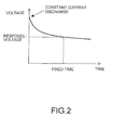
- SOF or SOH of a battery is determined based on whether response voltage when a prescribed constant current is discharged from the battery is bigger than a threshold or not.
- a constant current for example, 10A or 100A is discharged, it is determined whether SOF or SOH of a battery is appropriate or not, based on whether the response voltage value is bigger than a threshold value or not, at a time when a fixed time is passed after the start of the discharge.
- the magnitude of the discharge current of which the response voltage is to be estimated, or a threshold or the like for determining SOF or SOH of a battery may be determined on the basis of the permissible minimum value or the like of the operating voltage required by a load to which the power is supplied from the battery.
- Vc c ⁇ 0 + 1 + c ⁇ 1 ⁇ X + c ⁇ 2 ⁇ X + ... + cn - 1 ⁇ X n - 1 / d ⁇ 0 + d ⁇ 1 ⁇ X + ... + dn ⁇ X n
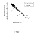
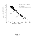
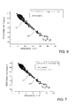
- R 2 denote the value R 2 which indicates the strength of correlation between the above described response-voltage correlative equation 21 to 25 and measured data 10.
- the R 2 value becomes larger as the order of the equation becomes higher, thus enabling approximation with higher accuracy.
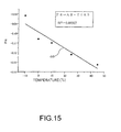
- the R 2 value of the response-voltage correlative equation 24 expressed in the exponential function is the same degree of magnitude as that of the response-voltage correlative equation 22 expressed in the second degree polynomial function.
- each coefficient of the response-voltage correlative equations shown in equation 1 to equation 3, or equation 4 to equation 8 is made to be function of temperature and SOC of the battery, and each coefficient is converted to a value at a predetermined temperature and SOC.
- each coefficient of response-voltage correlative equation is given in at least one of a polynomial function, an exponential function, and a reciprocal function using a variable of temperature and SOC of a battery.
- a polynomial function e.g., a polynomial function
- an exponential function e.g., a reciprocal function using a variable of temperature and SOC of a battery.
- the value of each coefficient is the value obtained by optimizing the response-voltage correlative equation (equation 9) for the measured response-voltage values at each temperature and SOC.
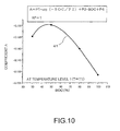
- FIG.8 shows the change of coefficient A of equation 9 corresponding to the change of temperature and SOC of a battery.
- the change of the coefficient A when the SOC is changed is shown by plotting (reference numerals 31 to 35 respectively) at each of five different temperature levels (hereinafter referred to as "T1 to T5"). From the figure, it is recognizable that the coefficient A varies in nonlinearity to SOC, and further the tendency of the change is substantially different depending on temperature.
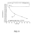
- FIG.9 shows the change of the coefficient B of the equation 9 corresponding to the change of the temperature and SOC of the battery.
- the change of the coefficient B corresponding to the change of the SOC is shown by plotting (reference numerals 36 to 40 respectively) at each different temperature level.
- the coefficient B varies in nonlinearity to SOC, and further the tendency of the change is substantially different depending on temperature.
- both of the coefficients A and B of equation 9 varies complicatedly in nonlinearity with the change of temperature and SOC of the battery.
- the optimal approximation of the complicated change of the coefficient A and B can be made by function s including at least one of a polynomial function, exponential function and reciprocal function of temperature and SOC of the battery.
- T and SOC represent temperature and SOC of a battery respectively.
- Coefficient B1 and Q used in the above equation 15 are optimized such that coefficient B indicates the variations as shown in FIG.9.
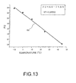
- FIG.16 shows the result of optimum fitting of the coefficient B1 at each temperature level by using the equation 15 showing dependency on the SOC.
- graph 51 to graph 55 fitting equation 15 to the change of coefficient B1 against the SOC at each temperature level show a good matching to the value of the coefficient B1.
- the optimized values of coefficients B2 and B3 of equation 16 are obtained on the basis of optimum value of coefficient Q at each temperature level.
- the optimized result of fitting of equation 16 to the optimized value of the coefficient Q is shown in the reference numeral 56 in FIG.17. From the figure, it is recognizable that equation 16 can approximate appropriately to the optimized values of coefficient Q. In the optimum approximation like this, the optimum values of the coefficients B1 to B3 are determined, and hereby it becomes possible to determine the optimum coefficient B corresponding to the change of temperature and SOC of the battery.
- the response voltage while applying a constant current discharge is expressed with a response-voltage correlative equation including at least one of a polynomial function, an exponential function, and a reciprocal function of the internal impedance or the internal resistance of the battery, and the coefficients used in the response-voltage correlative equation are expressed with at least one of the equation of the polynomial function and the exponential function using variables of temperature and SOC of the battery.
- the coefficients of the response-voltage correlative equation can be expressed with an equation composed of addition or accumulation of the both equations which are expressed by at least one of the polynomial function and the exponential function of the temperature and the SOC, respectively.
- the coefficients of the response-voltage correlative equation are expressed with a combination of the polynomial function and the exponential function, it is also possible similarly to determine the response voltage with high accuracy in the case that the reciprocal function is used.
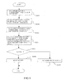
- FIG.1 shows a procedure for determining SOF and SOH of the battery by using a response-voltage correlative equation prepared in advance.
- the internal impedance X, the temperature T, and the state of charge SOC are measured at a predetermined timing to determine SOF and SOH of the battery (step 201).
- coefficient A is calculated by substituting the measured temperature T and state of charge SOC in equation 10 to equation 14 (step S202).
- the coefficient B is calculated by substituting the measured temperature T and the state of charge SOC in equation 15 and equation 16 (step S203).
- the response voltage Vc is calculated by substituting the measured internal impedance X in the response-voltage correlative equation (equation 9) in which the calculated coefficients A and B are applied (step S204).
- FIG.18 is a block diagram illustrating a schematic configuration of a battery power supply system 100 and a device 101 for monitoring state of a battery of the present invention.
- the battery power supply system 100 includes a device 101 for monitoring state of a battery, a battery 102, and a charge circuit 103, and is connected to a load 200.
- the device 101 for monitoring state of a battery includes an internal impedance measurement unit 111 for measuring the internal impedance of the battery 102, a temperature sensor 112 for measuring the temperature of the battery 102, an SOC sensor 113 for measuring the SOC of the battery, a controller 114 for carrying out various processing to determine SOH or SOF of the battery 102, and a storage 115 for storing a response-voltage correlative equation or the like.
- the processing to determine optimum values of the coefficients A and B is executed in advance according to the data that is obtained by performing a predetermined constant discharge.
- the response-voltage correlative equation represented in, for example, the equation 9, and the calculation formula for calculating the coefficients A and B, and the coefficients of the equation which are determined in advance are stored in the storage 115 in advance.
- the SOH or the SOF of the battery 102 is monitored periodically or predetermined timing by the device 101 for monitoring state of a battery. That is, the device 101 for monitoring state of a battery measures the internal impedance or the internal resistance, the temperature and the SOC of the battery 102 with the use of the internal impedance measurement unit 111, the temperature sensor 112, and the SOC sensor 113 respectively at monitoring timing, and transmits the data to the controller 114.
- the controller 114 along with inputting the above mentioned internal impedance or internal resistance, temperature and SOC, loads the response-voltage correlative equation (equation 9), the calculation equations (equation 10 to 16) to determine the coefficients A and B, and the coefficients of the equations from the storage 115.
- the response voltage Vc is calculated according to the flow chart in FIG.1, and then the SOF or the SOH of the battery 102 is determined by comparing the calculated result with the predetermined threshold V0.
- the battery power supply system 100 and the device 101 for monitoring state of a battery of the present embodiment it becomes possible to determine the response voltage from a voltage-response correlative equation, and the SOH or the SOF of the battery with high accuracy by comparing the estimated response voltage with a predetermined threshold. As the result of the determination, if the battery is determined to be lacking in SOF, it is also possible to charge the battery 102 promptly by using the charge circuit 103.
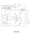
- FIG.20 is a block diagram illustrating a schematic configuration of the battery power supply system 100 and the device 101 for monitoring state of a battery of the present embodiment.
- the battery power supply system 100 includes a battery 101, a charge circuit 102, and a device 101 for monitoring state of a battery, and is connected to a load 10.
- the device 101 for monitoring state of a battery includes an internal impedance measurement unit 111 for measuring the internal impedance of the battery 101, a temperature sensor 112 for measuring temperature, an SOC sensor 113 for measuring SOC, a controller 114 for carrying out various processing to determine SOH or SOF of the battery 101, and a storage 115 for storing various data and various measured data that is necessary for the processing of the controller 114.
- the internal resistance or the internal impedance of the battery 101 is used as an index to determine SOH or SOF of the battery 101. Since the internal resistance or the internal impedance varies corresponding to temperature and SOC of the battery 101, it is required that the internal resistance or internal impedance is obtained at the temperature and the SOC which satisfy the condition for determining SOH or SOF.
- the internal resistance or the internal impedance in the standard state means the internal resistance or the internal impedance when the temperature and the SOC of the battery 101 are the predetermined standard temperature and the standard SOC, respectively.
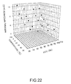
- the internal impedance of the battery varies with temperature and SOC, in addition, varies with SOH as well. Then, the variation of the internal impedance of a new battery without deterioration, and the variation of the internal impedance of a deteriorated battery with being used are shown in FIG.21 and FIG.22 respectively. Both of FIG.21 and FIG.22 three-dimensionally illustrate the variation of the internal impedance corresponding to temperature and SOC.
- the internal impedance varies rather largely with temperature. Also, it is illustrated that the internal impedance is varied along with the variation of SOC as well. In addition, it is recognizable that the internal impedance becomes larger as the deterioration of the battery advances by comparing FIG.21 with FIG.22. In particular, as the dependency of the internal impedance on temperature and SOC also varies along with SOH, it is recognizable that the variation of the internal impedance corresponding to temperature and SOC becomes larger as the deterioration of the battery goes ahead.
- the internal impedance is expressed by the function including at least one of the polynomial function, the exponential function and the reciprocal function of temperature and SOC.
- the coefficients included in the functions are also expressed by functions of one specified parameter (hereinafter referred to as "C").
- C one specified parameter
- the internal impedance is expressed by the first function including at least one of the polynomial function, the exponential function and the reciprocal function of temperature.
- At least one coefficient of the first function is expressed by the second function including at least one of the polynomial function, the exponential function and the reciprocal function of SOC.
- the coefficients of the first function and the second function are expressed may by functions of the parameter C.
- the formula to calculate the internal impedance is explained when the internal impedance is expressed by the first function including at least one of the polynomial function, the exponential function and the reciprocal function of temperature.
- AC0, AC1, AC2, and AC3 represent the coefficients of each term.
- FIG.23 An example of implementing the fitting of equation 17 to the internal impedance of the new battery 101 shown in FIG.21 is shown in FIG.23. As shown in FIG.23, it is recognizable that the internal impedance Z is accurately approximated with the third degree polynomial function of temperature T.
- coefficients AC0 to AC3, or AH1 to AH3, or AE1 to AE3 included in the above equation 17 to equation 19 are expressed further by using the second function including at least one of the polynomial function, the exponential function and the reciprocal function of SOC.
- AE ⁇ 3 1 / BH ⁇ 1 ⁇ S + BH ⁇ 2 + BH ⁇ 3
- BH1, BH2, and BH3 represent the coefficients of each term.
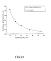
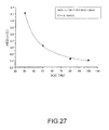
- FIG. 27 An example of fitting of equation 21 to the coefficient AE3 is shown in FIG. 27. It is recognizable that the reciprocal function of SOC S is able to approximate the coefficient AE3 highly accurately as shown in FIG.27.
- At least one of the coefficients included in the above equation 17 to equation 22 is expressed with the function of one specified parameter C.
- a calculation formula is explained with equation 19, and coefficient AE3, that is one of the coefficients of equation 19, is expressed with equation 22.
- coefficient AE1 and AE2 included in the equation 19 are expressed by the functions of the specified parameter C.
- linear functions are used as the functions of C.
- the internal impedance Z is expressed with equation 19 and equation 22 when the coefficients AE1 and AE 2 are expressed with linear functions of the specified parameter C.
- Z CE ⁇ 1 + CE ⁇ 2 ⁇ C ⁇ exp ⁇ - T / CE ⁇ 3 + CE ⁇ 4 ⁇ C ⁇ + BE ⁇ 1 ⁇ exp ( - S / BE ⁇ 2 ) + BE ⁇ 3
- AE1 CE1+CE2.C
- AE2 CE3+CE4.C
- CE1, CE2, CE3, CE4, BE1, BE2, and BE3 are predetermined constants.
- the controller 114 calculates the internal impedance at the predetermined temperature and SOC of the battery 101, by using, for example, the equation 23.
- the value of the specified parameter C needs to be determined. So, the controller 114 inputs each of the simultaneously measured internal impedance, temperature, and SOC from the internal impedance measurement unit 111, the temperature sensor 112, and the SOC sensor 113 respectively at the predetermined timing, and calculates the value of the specified parameter C by substituting these values in the equation 23.
- the equation 23 is the nonlinear function, it is impossible to obtain an analytic solution, but, the value of the specified parameter C can be obtained by performing a iterating operation by using, for example, Newton method or the like.
- the equation 23 becomes a final calculation formula of the internal impedance Z using variables of only temperature T and SOC S.
- the predetermined temperature T and SOC S in the right-hand side of the final calculation formula, it becomes possible to obtain the internal impedance Z of the battery 101 at that time.
- the internal impedance of the battery 101 is measured at some typical temperature and SOC conditions, and a final calculation formula is determined by determining the specified parameter C, the internal impedance is estimated at the respective predetermined standard temperature and standard SOC by using the final internal impedance calculation formula.
- FIG. 29 shows the result of estimating the internal impedance of the new battery
- FIG. 29(b) shows the result of the deteriorated battery
- the measured internal impedance and the estimated internal impedance at the standard temperature and standard SOC are identical, as a matter of course. Also, even in the case that the final calculation formula which is deduced at the respective measured temperatures and SOCs other than 25 degrees C. and 100% is used, it is recognizable that the internal impedance at the standard temperature and standard SOC is estimated with high accuracy. Hereby, it is understandable that the internal impedance at the respective any temperature and SOC can be estimated by the method for estimating the internal impedance, used in the present embodiment.
- the internal impedance Z at the time when the SOF is determined is calculated by substituting the temperature and the SOC at the time when the SOF is measured for the temperature T and the SOC S on the right-hand side of the final calculation formula.
- the threshold corresponding to the internal impedance for determining the SOF (hereinafter referred to as "SOF determination threshold") is stored in, for example, the storage 115 in advance, and then the controller 114 loads the SOF determining threshold from the storage 115 to compare the above calculated internal impedance Z with the SOF determining threshold.
- SOF determination threshold the threshold corresponding to the internal impedance for determining the SOF
- FIG.19 shows a process flow determining the final internal impedance calculation formula by calculating the specified parameter C based on the measured data of the battery 101
- FIG.19 (b) shows a process flow determining SOH of the battery 101.
- the determination of SOF in the battery 101 can be achieved by the similar process flow of FIG.19 (b).
- the internal impedance calculation formula is loaded from the storage 115 at step S11.
- equation 7 can be used as the internal impedance calculation formula.
- each measured value is input to the controller 114. And, each measured value being input is substituted in the internal impedance calculation formula at step S13.
- one equation using variable of only specified parameter C is obtained.
- the final internal impedance calculation formula is loaded from the storage 115 at step 21.
- the internal impedance for determining SOH is calculated by substituting the standard temperature and the standard SOC into the final internal impedance calculation formula.
- the internal impedance calculated at step 22 is compared with the SOH determination threshold.
- the SOH of the battery 101 is determined to be lowered at step S24. In this case, for example, an alert may be displayed.
- the SOH of the battery S25 is determined to be high at step S25.
- the effect to the internal impedance or the internal resistance caused by the variation of temperature and SOC of the battery is corrected by the calculation formula including at least one of the polynomial function, the exponential function, and the reciprocal function, it is possible to estimate the internal resistance or the internal impedance with high accuracy at any temperature and any SOC.
- the calculation formula including at least one of the polynomial function, the exponential function, and the reciprocal function it is possible to estimate the internal resistance or the internal impedance with high accuracy at any temperature and any SOC.
- SOH or SOF of the battery is determined SOH or SOF of the battery with high accuracy by using the estimated internal resistance or the estimated internal impedance.
- the present invention can provide a method for determining state of a battery so as to determine SOF or SOH of a battery with high accuracy by correcting the effect caused by the variation of temperature and SOC of a battery, since the coefficients of a correlation function between the response voltage at a constant current discharge and the internal impedance or the internal resistance can be calculated with high accuracy with the function of temperature and SOC of the battery.
- the calculation formula of the internal resistance or the internal impedance has an adjustment parameter to be matched to measured data, thus, the internal resistance or the internal impedance can be estimated with high accuracy by correcting the adjustment parameter even if there exists deterioration caused by aging or the like.
- the description of the present embodiment expresses examples of a method, and a device for determining state of a battery and a battery power supply system of the present invention, and not limited thereto. Detail configuration, detail operation, and others such as the method of the present embodiment for determining state of a battery may be changed as needed without departing from the sprit and scope of the present invention.
Landscapes
- Physics & Mathematics (AREA)
- General Physics & Mathematics (AREA)
- Secondary Cells (AREA)
- Tests Of Electric Status Of Batteries (AREA)
Applications Claiming Priority (2)
| Application Number | Priority Date | Filing Date | Title |
|---|---|---|---|
| JP2006313853A JP4805101B2 (ja) | 2006-11-21 | 2006-11-21 | バッテリ状態推定方法、バッテリ状態監視装置及びバッテリ電源システム |
| JP2006347080A JP4495141B2 (ja) | 2006-12-25 | 2006-12-25 | バッテリ状態判定方法、バッテリ状態判定装置及びバッテリ電源システム |
Publications (3)
| Publication Number | Publication Date |
|---|---|
| EP1933159A2 true EP1933159A2 (fr) | 2008-06-18 |
| EP1933159A3 EP1933159A3 (fr) | 2008-07-16 |
| EP1933159B1 EP1933159B1 (fr) | 2014-10-15 |
Family
ID=38982487
Family Applications (1)
| Application Number | Title | Priority Date | Filing Date |
|---|---|---|---|
| EP07120739.3A Active EP1933159B1 (fr) | 2006-11-21 | 2007-11-15 | Procédé et dispositif pour déterminer l'état d'une batterie, et système d'alimentation électrique à batterie associé |
Country Status (2)
| Country | Link |
|---|---|
| US (1) | US7593823B2 (fr) |
| EP (1) | EP1933159B1 (fr) |
Cited By (8)
| Publication number | Priority date | Publication date | Assignee | Title |
|---|---|---|---|---|
| ITMI20091868A1 (it) * | 2009-10-27 | 2011-04-28 | F I A M M Spa | Metodo per la rilevazione continua dell'efficienza di una batteria specie di una batteria installata in autoveicoli e dispositivo utilizzante tale metodo |
| WO2011004249A3 (fr) * | 2009-07-08 | 2011-05-05 | Toyota Jidosha Kabushiki Kaisha | Appareil pour l'estimation de la température d'une batterie secondaire |
| WO2012076220A1 (fr) * | 2010-12-10 | 2012-06-14 | Sb Limotive Company Ltd. | Procédé permettant de déterminer des paramètres de fonctionnement d'une batterie, système de gestion de batterie et batterie |
| WO2014083168A1 (fr) * | 2012-11-29 | 2014-06-05 | Phoenix Contact Gmbh & Co.Kg | Procédé et dispositif de surveillance de la capacité de fonctionnement d'un accumulateur |
| CN103928723A (zh) * | 2013-01-11 | 2014-07-16 | 通用汽车环球科技运作有限责任公司 | 电池区段平衡方法及系统 |
| EP2494673B1 (fr) * | 2009-10-29 | 2016-10-26 | Commissariat à l'Énergie Atomique et aux Énergies Alternatives | Procédé de charge ou de décharge d'une batterie pour déterminer la fin de charge ou de décharge en fonction de mesures de courant et de température |
| EP2980595A4 (fr) * | 2013-03-26 | 2016-11-23 | Toshiba Kk | Procédé d'estimation de durée de vie de batterie et dispositif d'estimation de durée de vie de batterie |
| WO2023006330A1 (fr) * | 2021-07-27 | 2023-02-02 | Robert Bosch Gmbh | Procédé de compensation de la résistance interne d'un dispositif de stockage d'énergie et système de compensation de la résistance interne |
Families Citing this family (42)
| Publication number | Priority date | Publication date | Assignee | Title |
|---|---|---|---|---|
| EP1933158B1 (fr) | 2005-09-16 | 2018-04-25 | The Furukawa Electric Co., Ltd. | Méthode d estimation de dégradation de cellule secondaire, dispositif d estimation de dégradation de cellule secondaire et système d alimentation |
| US7593823B2 (en) | 2006-11-21 | 2009-09-22 | The Furukawa Electric Co., Ltd | Method and device for determining state of battery, and battery power supply system therewith |
| US7899631B2 (en) * | 2007-03-29 | 2011-03-01 | The Furukawa Electric Co., Ltd. | Method and device for estimating battery residual capacity, and battery power supply system |
| US8283891B2 (en) * | 2008-03-21 | 2012-10-09 | Rochester Institute Of Technology | Power source health assessment methods and systems thereof |
| JP5106272B2 (ja) * | 2008-06-30 | 2012-12-26 | パナソニック株式会社 | 劣化判定回路、電源装置、及び二次電池の劣化判定方法 |
| JP2010019758A (ja) * | 2008-07-11 | 2010-01-28 | Mitsumi Electric Co Ltd | 電池状態検知装置 |
| US8008893B2 (en) * | 2009-02-06 | 2011-08-30 | Cobasys, Llc | Battery analysis system |
| US10132870B2 (en) * | 2009-04-24 | 2018-11-20 | Dell Products L.P. | Dynamic discharging to detect derated battery cells |
| WO2011001471A1 (fr) * | 2009-07-02 | 2011-01-06 | トヨタ自動車株式会社 | Dispositif et procédé pour détecter l'état interne d'une batterie |
| US8965721B2 (en) * | 2009-09-30 | 2015-02-24 | Tesla Motors, Inc. | Determining battery DC impedance |
| US20110316545A1 (en) * | 2010-06-29 | 2011-12-29 | Rylan Ian Grant | Electronic Detection of Signatures |
| KR101172183B1 (ko) * | 2010-09-27 | 2012-08-07 | 현대자동차주식회사 | 차량의 배터리 soh 추정 장치 및 방법 |
| FR2965360B1 (fr) * | 2010-09-27 | 2013-03-29 | IFP Energies Nouvelles | Procede de diagnostic in situ de batteries par spectroscopie d'impedance electrochimique |
| WO2012046285A1 (fr) | 2010-10-04 | 2012-04-12 | 古河電気工業株式会社 | Procédé permettant d'évaluer l'état d'une batterie et système d'alimentation |
| US9091735B2 (en) | 2010-10-26 | 2015-07-28 | GM Global Technology Operations LLC | Method for determining a state of a rechargeable battery device in real time |
| JP2012198175A (ja) * | 2011-03-23 | 2012-10-18 | Suzuki Motor Corp | バッテリ状態監視装置 |
| JP5648574B2 (ja) * | 2011-04-28 | 2015-01-07 | スズキ株式会社 | 車両用電源制御装置 |
| KR101222207B1 (ko) | 2011-05-25 | 2013-01-15 | 삼성에스디아이 주식회사 | 배터리 내부 저항 추정 장치 및 그를 포함하는 배터리 팩 |
| WO2013008814A1 (fr) * | 2011-07-13 | 2013-01-17 | 三洋電機株式会社 | Dispositif d'alimentation électrique et véhicule équipé du dispositif d'alimentation électrique |
| WO2013085996A1 (fr) * | 2011-12-05 | 2013-06-13 | The Goverment Of The United States Of Amreica, As Represented By The Secretary Of The Navy | Système et procédé de surveillance de l'état d'une batterie |
| KR20150004376A (ko) | 2012-04-12 | 2015-01-12 | 이스트 펜 매뉴팩츄어링 컴퍼니 | 배터리 용량의 관리 |
| US8994340B2 (en) * | 2012-05-15 | 2015-03-31 | GM Global Technology Operations LLC | Cell temperature and degradation measurement in lithium ion battery systems using cell voltage and pack current measurement and the relation of cell impedance to temperature based on signal given by the power inverter |
| CN104813180B (zh) * | 2013-02-19 | 2017-04-05 | 古河电气工业株式会社 | 二次电池劣化判定方法及二次电池劣化判定装置 |
| JP6479650B2 (ja) * | 2013-03-07 | 2019-03-06 | 古河電気工業株式会社 | 二次電池状態検出装置および二次電池状態検出方法 |
| FR3006450B1 (fr) * | 2013-06-04 | 2015-05-22 | Renault Sa | Procede pour estimer l'etat de sante d'une cellule electrochimique de stockage d'energie electrique |
| TWI476415B (zh) | 2013-08-16 | 2015-03-11 | Ind Tech Res Inst | 阻抗分析裝置及方法 |
| CN103744029B (zh) * | 2013-12-27 | 2017-03-29 | 高新兴科技集团股份有限公司 | 一种基于内阻测量单体电池剩余容量的估算方法 |
| KR102171096B1 (ko) | 2014-04-21 | 2020-10-28 | 삼성전자주식회사 | 전기 자동차의 운행 중 배터리의 수명을 추정하는 장치 및 방법 |
| KR102165937B1 (ko) * | 2014-05-30 | 2020-10-14 | 삼성전자주식회사 | 배터리 관리 방법 및 장치 |
| US10150479B2 (en) | 2016-09-02 | 2018-12-11 | Lear Corporation | Battery state of function prediction with self-learning |
| WO2018162023A2 (fr) * | 2017-03-06 | 2018-09-13 | Volvo Truck Corporation | Procédé d'estimation de puissance d'état de batterie et système de surveillance d'état de batterie |
| CN106918789B (zh) * | 2017-05-10 | 2019-05-14 | 成都理工大学 | 一种soc-soh联合在线实时估计和在线修正方法 |
| US10288029B2 (en) | 2017-05-26 | 2019-05-14 | Lear Corporation | Battery state of function prediction with warm/cold cranking recognition and self-correction |
| DE102017209182A1 (de) * | 2017-05-31 | 2018-12-06 | Bayerische Motoren Werke Aktiengesellschaft | Verfahren und Vorrichtung zum Bestimmen einer Betriebstemperatur, Betriebsverfahren für eine Batteriezelle, Steuereinheit für eine Batteriezelle und Arbeitsvorrichtung |
| US11525862B2 (en) | 2019-04-08 | 2022-12-13 | Ningde Amperex Technology Limited | Methods, storage media, and electronic devices for calculating short-circuit current of battery |
| DE102019133921A1 (de) * | 2019-12-11 | 2021-06-17 | Bayerische Motoren Werke Aktiengesellschaft | Verfahren, Vorrichtung, System, Elektrofahrzeug, Computerprogramm und Speichermedium zum Laden oder Entladen einer Zelle eines elektrischen Energiespeichers |
| KR20210156618A (ko) * | 2020-06-18 | 2021-12-27 | 주식회사 엘지에너지솔루션 | 배터리 관리 시스템, 배터리 관리 방법, 배터리 팩 및 전기 차량 |
| CN112305438A (zh) * | 2020-09-15 | 2021-02-02 | 深圳新恒业电池科技有限公司 | 电池内阻的测量方法、装置、终端及存储介质 |
| KR102663022B1 (ko) * | 2021-03-26 | 2024-05-07 | 삼성에스디아이 주식회사 | 배터리 시스템 및 이의 제어 방법 |
| CN113109715B (zh) * | 2021-03-29 | 2022-07-05 | 东华大学 | 基于特征选择和支持向量回归的电池健康状况预测方法 |
| CN113465773B (zh) * | 2021-07-28 | 2023-05-05 | 傲普(上海)新能源有限公司 | 一种测算锂离子电池内部温度的方法 |
| CN116243197B (zh) * | 2023-05-12 | 2023-07-21 | 国民技术股份有限公司 | 电池soh预测方法和装置 |
Citations (4)
| Publication number | Priority date | Publication date | Assignee | Title |
|---|---|---|---|---|
| JP2001228226A (ja) | 2000-02-21 | 2001-08-24 | Yazaki Corp | バッテリーの劣化度判定装置及びバッテリーの劣化度判定装置における劣化度算出プログラムを記録した記録媒体 |
| US20040128089A1 (en) | 2002-12-29 | 2004-07-01 | Evgenij Barsoukov | Circuit and method for determining battery impedance increase with aging |
| JP2005037380A (ja) | 2003-06-27 | 2005-02-10 | Furukawa Electric Co Ltd:The | 蓄電池の劣化判定方法および劣化判定装置 |
| JP2005091217A (ja) | 2003-09-18 | 2005-04-07 | Furukawa Electric Co Ltd:The | 二次電池劣化状態判定方法、二次電池劣化状態判定装置及び電源システム |
Family Cites Families (11)
| Publication number | Priority date | Publication date | Assignee | Title |
|---|---|---|---|---|
| US4940525A (en) * | 1987-05-08 | 1990-07-10 | The Dow Chemical Company | Low equivalent weight sulfonic fluoropolymers |
| DE60135080D1 (de) * | 2000-12-26 | 2008-09-11 | Asahi Glass Co Ltd | Festpolymer-Elektrolyt Material, flüssige Zusammensetzung, Festpolymer Brennstoffzelle und Fluorpolymer |
| DE10210516B4 (de) * | 2002-03-09 | 2004-02-26 | Vb Autobatterie Gmbh | Verfahren und Einrichtung zum Ermitteln der Funktionsfähigkeit einer Speicherbatterie |
| JP4219702B2 (ja) * | 2003-02-06 | 2009-02-04 | 東京エレクトロン株式会社 | 減圧処理装置 |
| EP2626716B1 (fr) * | 2003-06-27 | 2015-09-16 | The Furukawa Electric Co., Ltd. | Dispositif de jugement et procédé pour juger la détérioration d'accumulateur/de cellule secondaire. |
| DE602005024002D1 (de) * | 2004-06-22 | 2010-11-18 | Asahi Glass Co Ltd | Elektrolytmembran für eine festpolymer-brennstoffzelle, herstellungsverfahren dafür und membranelektrodenbaugruppe für eine festpolymer-brennstoffzelle |
| ATE491237T1 (de) * | 2004-06-22 | 2010-12-15 | Asahi Glass Co Ltd | Flüssige zusammensetzung, verfahren zu deren herstellung und verfahren zur herstellung einer membranelektrodenbaugruppe für polymerelektrolyt- brennstoffzelle |
| JP5095089B2 (ja) * | 2005-05-31 | 2012-12-12 | 株式会社豊田中央研究所 | 固体高分子電解質、並びに、固体高分子型燃料電池及びその製造方法 |
| US8628871B2 (en) * | 2005-10-28 | 2014-01-14 | 3M Innovative Properties Company | High durability fuel cell components with cerium salt additives |
| US8367267B2 (en) * | 2005-10-28 | 2013-02-05 | 3M Innovative Properties Company | High durability fuel cell components with cerium oxide additives |
| US7593823B2 (en) | 2006-11-21 | 2009-09-22 | The Furukawa Electric Co., Ltd | Method and device for determining state of battery, and battery power supply system therewith |
-
2007
- 2007-11-05 US US11/934,934 patent/US7593823B2/en active Active
- 2007-11-15 EP EP07120739.3A patent/EP1933159B1/fr active Active
Patent Citations (4)
| Publication number | Priority date | Publication date | Assignee | Title |
|---|---|---|---|---|
| JP2001228226A (ja) | 2000-02-21 | 2001-08-24 | Yazaki Corp | バッテリーの劣化度判定装置及びバッテリーの劣化度判定装置における劣化度算出プログラムを記録した記録媒体 |
| US20040128089A1 (en) | 2002-12-29 | 2004-07-01 | Evgenij Barsoukov | Circuit and method for determining battery impedance increase with aging |
| JP2005037380A (ja) | 2003-06-27 | 2005-02-10 | Furukawa Electric Co Ltd:The | 蓄電池の劣化判定方法および劣化判定装置 |
| JP2005091217A (ja) | 2003-09-18 | 2005-04-07 | Furukawa Electric Co Ltd:The | 二次電池劣化状態判定方法、二次電池劣化状態判定装置及び電源システム |
Cited By (16)
| Publication number | Priority date | Publication date | Assignee | Title |
|---|---|---|---|---|
| WO2011004249A3 (fr) * | 2009-07-08 | 2011-05-05 | Toyota Jidosha Kabushiki Kaisha | Appareil pour l'estimation de la température d'une batterie secondaire |
| US8684596B2 (en) | 2009-07-08 | 2014-04-01 | Toyota Jidosha Kabushiki Kaisha | Secondary battery temperature-estimating apparatus and method |
| US8788142B2 (en) | 2009-10-27 | 2014-07-22 | F.I.A.M.M. S.P.A. | Method for the continuous measurement of the efficiency of a battery, especially a battery installed in motor vehicles, and a device utilizing this method |
| WO2011050924A1 (fr) * | 2009-10-27 | 2011-05-05 | F.I.A.M.M. S.P.A. | Procédé de mesure continue de l'efficacité d'une batterie, notamment une batterie installée dans un véhicule à moteur, et dispositif utilisant ce procédé |
| ITMI20091868A1 (it) * | 2009-10-27 | 2011-04-28 | F I A M M Spa | Metodo per la rilevazione continua dell'efficienza di una batteria specie di una batteria installata in autoveicoli e dispositivo utilizzante tale metodo |
| CN102656469A (zh) * | 2009-10-27 | 2012-09-05 | F.I.A.M.M.股份公司 | 用于持续测量电池(尤其是安装在机动车内的电池)效率的方法以及利用该方法的设备 |
| EP2494673B1 (fr) * | 2009-10-29 | 2016-10-26 | Commissariat à l'Énergie Atomique et aux Énergies Alternatives | Procédé de charge ou de décharge d'une batterie pour déterminer la fin de charge ou de décharge en fonction de mesures de courant et de température |
| US9476947B2 (en) | 2010-12-10 | 2016-10-25 | Robert Bosch Gmbh | Method for ascertaining operating parameters of a battery, battery management system, and battery |
| WO2012076220A1 (fr) * | 2010-12-10 | 2012-06-14 | Sb Limotive Company Ltd. | Procédé permettant de déterminer des paramètres de fonctionnement d'une batterie, système de gestion de batterie et batterie |
| WO2014083168A1 (fr) * | 2012-11-29 | 2014-06-05 | Phoenix Contact Gmbh & Co.Kg | Procédé et dispositif de surveillance de la capacité de fonctionnement d'un accumulateur |
| CN103928723A (zh) * | 2013-01-11 | 2014-07-16 | 通用汽车环球科技运作有限责任公司 | 电池区段平衡方法及系统 |
| US20140197776A1 (en) * | 2013-01-11 | 2014-07-17 | GM Global Technology Operations LLC | Battery section balancing methods and systems |
| US9077181B2 (en) * | 2013-01-11 | 2015-07-07 | GM Global Technology Operations LLC | Battery section balancing methods and systems |
| CN103928723B (zh) * | 2013-01-11 | 2017-04-12 | 通用汽车环球科技运作有限责任公司 | 电池区段平衡方法及系统 |
| EP2980595A4 (fr) * | 2013-03-26 | 2016-11-23 | Toshiba Kk | Procédé d'estimation de durée de vie de batterie et dispositif d'estimation de durée de vie de batterie |
| WO2023006330A1 (fr) * | 2021-07-27 | 2023-02-02 | Robert Bosch Gmbh | Procédé de compensation de la résistance interne d'un dispositif de stockage d'énergie et système de compensation de la résistance interne |
Also Published As
| Publication number | Publication date |
|---|---|
| EP1933159B1 (fr) | 2014-10-15 |
| US20080120050A1 (en) | 2008-05-22 |
| EP1933159A3 (fr) | 2008-07-16 |
| US7593823B2 (en) | 2009-09-22 |
Similar Documents
| Publication | Publication Date | Title |
|---|---|---|
| EP1933159B1 (fr) | Procédé et dispositif pour déterminer l'état d'une batterie, et système d'alimentation électrique à batterie associé | |
| EP3742181B1 (fr) | Procédé et appareil pour la correction de l'état de charge, système de gestion de batterie et support d'enregistrement | |
| KR102080632B1 (ko) | 배터리관리시스템 및 그 운용방법 | |
| KR101509001B1 (ko) | 차량용 고전압 배터리의 열화 판정 장치 및 방법 | |
| EP1873542B1 (fr) | Appareil et méthode pour évaluer l'état de charge d'une pile | |
| CN101187697B (zh) | 电池状态判定方法、电池状态判定装置及电池电源系统 | |
| US10162014B2 (en) | Battery state determining device | |
| US6789026B2 (en) | Circuit and method for monitoring battery state of charge | |
| EP1975635B1 (fr) | Procédé et dispositif pour estimer la capacité résiduelle d'une batterie et système d'alimentation électrique par batterie | |
| JP7112252B2 (ja) | 動作条件下で電流を直接検知することなく、バッテリパックまたはセルの電流及び充電状態を推定する方法 | |
| CN109507604B (zh) | 电池输出监控装置和电池输出监控方法 | |
| KR102557731B1 (ko) | 배터리의 순간 개방 회로 전압 프로파일의 추정 방법 및 장치 | |
| US20130013237A1 (en) | State-of-charge estimation method, state-of-charge estimation device, and secondary-battery power system | |
| EP2860539B1 (fr) | Procédé d'estimation d'un état de charge et dispositif d'estimation d'un état de charge | |
| RU2690724C1 (ru) | Устройство оценки коэффициента емкости или способ оценки коэффициента емкости | |
| CN103852727A (zh) | 动力电池荷电状态在线估算方法和装置 | |
| EP3730957A1 (fr) | Dispositif et procédé de calcul de capacité de charge pour système de stockage d'énergie | |
| EP2827163A1 (fr) | Estimation d'état de charge avec compensation de température pour batteries rechargeables | |
| EP3015835B1 (fr) | Procédé et système permettant de déterminer la température de fonctionnement d'une cellule d'un ensemble accumulateur de charge électrique sans capteurs de température physique, en particulier pour véhicules à moteur électrique ou hybride | |
| US20120109557A1 (en) | Method for calibrating an electrochemical battery | |
| CN102576053B (zh) | 电池状态推断方法及电源系统 | |
| JP4495141B2 (ja) | バッテリ状態判定方法、バッテリ状態判定装置及びバッテリ電源システム | |
| JP2007108063A (ja) | 二次電池劣化判定方法、二次電池劣化判定装置、及び電源システム | |
| CN120468661A (zh) | Soc修正方法、装置、设备、介质、产品、电池管理系统及用电设备 | |
| KR20250169535A (ko) | 이차전지 유닛 충전 상태 추정 장치, 이차전지 유닛 충전 상태 추정 방법 및 이차전지 유닛 충전 상태 추정 프로그램 |
Legal Events
| Date | Code | Title | Description |
|---|---|---|---|
| PUAI | Public reference made under article 153(3) epc to a published international application that has entered the european phase |
Free format text: ORIGINAL CODE: 0009012 |
|
| PUAL | Search report despatched |
Free format text: ORIGINAL CODE: 0009013 |
|
| AK | Designated contracting states |
Kind code of ref document: A2 Designated state(s): AT BE BG CH CY CZ DE DK EE ES FI FR GB GR HU IE IS IT LI LT LU LV MC MT NL PL PT RO SE SI SK TR |
|
| AX | Request for extension of the european patent |
Extension state: AL BA HR MK RS |
|
| AK | Designated contracting states |
Kind code of ref document: A3 Designated state(s): AT BE BG CH CY CZ DE DK EE ES FI FR GB GR HU IE IS IT LI LT LU LV MC MT NL PL PT RO SE SI SK TR |
|
| AX | Request for extension of the european patent |
Extension state: AL BA HR MK RS |
|
| 17P | Request for examination filed |
Effective date: 20081219 |
|
| 17Q | First examination report despatched |
Effective date: 20090130 |
|
| AKX | Designation fees paid |
Designated state(s): DE FR GB |
|
| R17C | First examination report despatched (corrected) |
Effective date: 20090304 |
|
| GRAP | Despatch of communication of intention to grant a patent |
Free format text: ORIGINAL CODE: EPIDOSNIGR1 |
|
| GRAJ | Information related to disapproval of communication of intention to grant by the applicant or resumption of examination proceedings by the epo deleted |
Free format text: ORIGINAL CODE: EPIDOSDIGR1 |
|
| INTG | Intention to grant announced |
Effective date: 20140430 |
|
| GRAP | Despatch of communication of intention to grant a patent |
Free format text: ORIGINAL CODE: EPIDOSNIGR1 |
|
| GRAJ | Information related to disapproval of communication of intention to grant by the applicant or resumption of examination proceedings by the epo deleted |
Free format text: ORIGINAL CODE: EPIDOSDIGR1 |
|
| GRAP | Despatch of communication of intention to grant a patent |
Free format text: ORIGINAL CODE: EPIDOSNIGR1 |
|
| INTG | Intention to grant announced |
Effective date: 20140602 |
|
| INTG | Intention to grant announced |
Effective date: 20140612 |
|
| GRAS | Grant fee paid |
Free format text: ORIGINAL CODE: EPIDOSNIGR3 |
|
| GRAA | (expected) grant |
Free format text: ORIGINAL CODE: 0009210 |
|
| AK | Designated contracting states |
Kind code of ref document: B1 Designated state(s): DE FR GB |
|
| RAP1 | Party data changed (applicant data changed or rights of an application transferred) |
Owner name: FURUKAWA ELECTRIC CO., LTD. |
|
| REG | Reference to a national code |
Ref country code: GB Ref legal event code: FG4D |
|
| RIN1 | Information on inventor provided before grant (corrected) |
Inventor name: CHIKAZAWA, KEIKO Inventor name: IWANE, NORIYASU Inventor name: MORII, KEISUKE |
|
| REG | Reference to a national code |
Ref country code: DE Ref legal event code: R096 Ref document number: 602007038888 Country of ref document: DE Effective date: 20141127 |
|
| REG | Reference to a national code |
Ref country code: DE Ref legal event code: R097 Ref document number: 602007038888 Country of ref document: DE |
|
| PLBE | No opposition filed within time limit |
Free format text: ORIGINAL CODE: 0009261 |
|
| STAA | Information on the status of an ep patent application or granted ep patent |
Free format text: STATUS: NO OPPOSITION FILED WITHIN TIME LIMIT |
|
| 26N | No opposition filed |
Effective date: 20150716 |
|
| REG | Reference to a national code |
Ref country code: FR Ref legal event code: PLFP Year of fee payment: 9 |
|
| REG | Reference to a national code |
Ref country code: FR Ref legal event code: PLFP Year of fee payment: 10 |
|
| REG | Reference to a national code |
Ref country code: FR Ref legal event code: PLFP Year of fee payment: 11 |
|
| REG | Reference to a national code |
Ref country code: FR Ref legal event code: PLFP Year of fee payment: 12 |
|
| P01 | Opt-out of the competence of the unified patent court (upc) registered |
Effective date: 20230512 |
|
| PGFP | Annual fee paid to national office [announced via postgrant information from national office to epo] |
Ref country code: FR Payment date: 20250930 Year of fee payment: 19 |
|
| PGFP | Annual fee paid to national office [announced via postgrant information from national office to epo] |
Ref country code: DE Payment date: 20250930 Year of fee payment: 19 |
|
| PGFP | Annual fee paid to national office [announced via postgrant information from national office to epo] |
Ref country code: GB Payment date: 20251001 Year of fee payment: 19 |