EP1933199A2 - Appareil à lentilles et système de caméra - Google Patents
Appareil à lentilles et système de caméra Download PDFInfo
- Publication number
- EP1933199A2 EP1933199A2 EP07122691A EP07122691A EP1933199A2 EP 1933199 A2 EP1933199 A2 EP 1933199A2 EP 07122691 A EP07122691 A EP 07122691A EP 07122691 A EP07122691 A EP 07122691A EP 1933199 A2 EP1933199 A2 EP 1933199A2
- Authority
- EP
- European Patent Office
- Prior art keywords
- lens
- aperture
- extender
- lens apparatus
- lenses
- Prior art date
- Legal status (The legal status is an assumption and is not a legal conclusion. Google has not performed a legal analysis and makes no representation as to the accuracy of the status listed.)
- Granted
Links
- 239000004606 Fillers/Extenders Substances 0.000 claims abstract description 57
- 230000003287 optical effect Effects 0.000 claims abstract description 15
- 238000001514 detection method Methods 0.000 description 8
- 238000000034 method Methods 0.000 description 5
- 238000010586 diagram Methods 0.000 description 3
- 230000007423 decrease Effects 0.000 description 2
- 230000006870 function Effects 0.000 description 1
- 238000012986 modification Methods 0.000 description 1
- 230000004048 modification Effects 0.000 description 1
Images



Classifications
-
- G—PHYSICS
- G03—PHOTOGRAPHY; CINEMATOGRAPHY; ANALOGOUS TECHNIQUES USING WAVES OTHER THAN OPTICAL WAVES; ELECTROGRAPHY; HOLOGRAPHY
- G03B—APPARATUS OR ARRANGEMENTS FOR TAKING PHOTOGRAPHS OR FOR PROJECTING OR VIEWING THEM; APPARATUS OR ARRANGEMENTS EMPLOYING ANALOGOUS TECHNIQUES USING WAVES OTHER THAN OPTICAL WAVES; ACCESSORIES THEREFOR
- G03B7/00—Control of exposure by setting shutters, diaphragms or filters, separately or conjointly
- G03B7/08—Control effected solely on the basis of the response, to the intensity of the light received by the camera, of a built-in light-sensitive device
- G03B7/091—Digital circuits
- G03B7/095—Digital circuits for control of aperture
-
- G—PHYSICS
- G02—OPTICS
- G02B—OPTICAL ELEMENTS, SYSTEMS OR APPARATUS
- G02B7/00—Mountings, adjusting means, or light-tight connections, for optical elements
- G02B7/02—Mountings, adjusting means, or light-tight connections, for optical elements for lenses
- G02B7/04—Mountings, adjusting means, or light-tight connections, for optical elements for lenses with mechanism for focusing or varying magnification
- G02B7/10—Mountings, adjusting means, or light-tight connections, for optical elements for lenses with mechanism for focusing or varying magnification by relative axial movement of several lenses, e.g. of varifocal objective lens
- G02B7/102—Mountings, adjusting means, or light-tight connections, for optical elements for lenses with mechanism for focusing or varying magnification by relative axial movement of several lenses, e.g. of varifocal objective lens controlled by a microcomputer
-
- G—PHYSICS
- G03—PHOTOGRAPHY; CINEMATOGRAPHY; ANALOGOUS TECHNIQUES USING WAVES OTHER THAN OPTICAL WAVES; ELECTROGRAPHY; HOLOGRAPHY
- G03B—APPARATUS OR ARRANGEMENTS FOR TAKING PHOTOGRAPHS OR FOR PROJECTING OR VIEWING THEM; APPARATUS OR ARRANGEMENTS EMPLOYING ANALOGOUS TECHNIQUES USING WAVES OTHER THAN OPTICAL WAVES; ACCESSORIES THEREFOR
- G03B17/00—Details of cameras or camera bodies; Accessories therefor
- G03B17/02—Bodies
- G03B17/12—Bodies with means for supporting objectives, supplementary lenses, filters, masks, or turrets
-
- G—PHYSICS
- G03—PHOTOGRAPHY; CINEMATOGRAPHY; ANALOGOUS TECHNIQUES USING WAVES OTHER THAN OPTICAL WAVES; ELECTROGRAPHY; HOLOGRAPHY
- G03B—APPARATUS OR ARRANGEMENTS FOR TAKING PHOTOGRAPHS OR FOR PROJECTING OR VIEWING THEM; APPARATUS OR ARRANGEMENTS EMPLOYING ANALOGOUS TECHNIQUES USING WAVES OTHER THAN OPTICAL WAVES; ACCESSORIES THEREFOR
- G03B7/00—Control of exposure by setting shutters, diaphragms or filters, separately or conjointly
- G03B7/20—Control of exposure by setting shutters, diaphragms or filters, separately or conjointly in accordance with change of lens
-
- H—ELECTRICITY
- H04—ELECTRIC COMMUNICATION TECHNIQUE
- H04N—PICTORIAL COMMUNICATION, e.g. TELEVISION
- H04N23/00—Cameras or camera modules comprising electronic image sensors; Control thereof
- H04N23/60—Control of cameras or camera modules
- H04N23/66—Remote control of cameras or camera parts, e.g. by remote control devices
- H04N23/663—Remote control of cameras or camera parts, e.g. by remote control devices for controlling interchangeable camera parts based on electronic image sensor signals
Definitions
- the present invention relates to a lens apparatus and a camera system in which the aperture value is automatically adjusted to keep the brightness of the image constant even when the image taking magnification is changed by an extender lens.
- the F-number changes with the focal length.
- the aperture value is corrected according to the magnification of the extender lens, whereby the F-number is controlled to be constant irrespective of the magnification of the extender lens.
- aperture correction is performed so that the aperture or stop is opened to double the light quantity so as not to change the brightness when the magnification of the extender lens is changed.
- the present invention has been made in view of the above-mentioned problem.
- a lens apparatus as specified in claims 1 to 5.
- a camera system as specified in claim 6.
- FIG. 1 is a diagram showing the configuration of a television camera lens apparatus according to an embodiment.
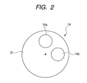
- FIG. 2 illustrates the structure of an extender lens.
- FIG. 3 illustrates relationship between aperture values and F-numbers.
- FIG. 4 is a graph showing errors in relation to F-numbers
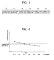
- FIG. 5 illustrates a correction data table
- FIG. 6 illustrates calculation of error data
- FIG. 7 is a flow chart of a control process.
- FIG. 1 is a diagram showing the configuration of the embodiment.
- a television camera lens 10 is mounted on and connected with a television camera 40.
- the television camera lens 10 has a focusing lens 11, a zooming lens 12, a stop 13 and a plurality of extender lenses 14 arranged to be moveable into the optical axis.
- the television camera lens 10 is also provided with drive motors 15, 16, 17, drive amplifiers 18, 19, 20 and D/A converters 21, 22, 23 to drive the lenses 11, 12 and the stop (aperture) 13.
- the drive motors 15, 16, 17, the drive amplifiers 18, 19, 20 and the D/A converters 21, 22, 23 are configured to be operated by commands from a CPU 24 according to a program.
- the positions of the lenses 11, 12 and the stop 13 are detected respectively by a focus position detection sensor 25, a zoom position detection sensor 26 and a potentiometer 27, which are connected with the CPU 24 via A/D converters 28, 29, 30 respectively.
- the plurality of extender lenses 14 is held on a turret 31, which is driven by a drive motor 33 based on a command from the CPU 24 through a drive amplifier 32.
- the position of the turret 31 is detected by a position detection sensor 34.
- the CPU 24 functioning as control means is connected with a ROM 35 serving as memory means.
- the television camera 40 has an image pickup element 41 arranged on the optical axis of the television camera lens 10.
- the television camera 40 is also provided with an aperture value setting circuit 42 and a CPU 43.
- the output of the aperture value setting circuit 42 is connected to the CPU 43.
- the CPU 43 is connected with the CPU 24 in the television camera lens 10.
- the focusing lens 11 and the zooming lens 12 are moved along the optical axis by the focus drive motor 15 and the zoom drive motor 16 respectively.
- the drive motors 15 and 16 are controlled by the drive amplifiers 18 and 19 respectively.
- the focusing lens 11 and the zooming lens 12 are driven according to command signals that are generated by the CPU 24 with reference to signals from the position detection sensors 25 and 26 that detect the positions of the respective lenses.
- the aperture value of the stop 13 is adapted to be varied by the stop drive motor 17.
- the stop drive motor 17 is controlled by the stop drive amplifier 20.
- the stop 13 is driven according to a command signal that is generated by the CPU 24 with reference to a detection signal of the potentiometer 27 that detects the aperture value.
- FIG. 2 is a diagram illustrating the extender lenses 14, in which an extender lens 14a having magnification factor of 1 and an extender lens 14b having magnification factor of 2 are arranged on a rotatable disk-like turret 31.
- the turret 31 is rotated by the drive motor 33, whereby the extender lenses 14a and 14b are switched or selectively positioned on the optical axis.
- the drive motor 33 is controlled by the drive amplifier 32 and driven according to a command signal input from the CPU 24.
- Which extender lens 14 is being selected or the rotational position of the turret 31 is detected by the position detection sensor 34, and the detection result is input to the CPU 24.
- the CPU 24 can store information on the drive command signals supplied to identify which extender lens is currently in the optical path.
- the CPU 24 outputs command signals to the drive amplifiers to control them based on command signals for the focusing lens 11, the zooming lens 12 and the stop 13 input from the respective sensors and the like.
- FIG. 3 shows the relationship between the range of the value of the aperture control signal that prescribes the aperture value and the F-number in the case in which the extender lens 14a having magnification factor of 1 is inserted in the optical path, and the F-number in the case in which the extender lens 14b having magnification factor of 2 is inserted.
- the value of the aperture control signal ranges from Vo to Vc, which corresponds to the variable range of the aperture value from O (open) to C (close).
- the F-number varies over the range of F1.4 to F16 as the aperture value varies over the variable range of O to C.
- the F-number generally becomes larger in relation to the variable range of the aperture value. Accordingly, if the aperture value is set to the position prescribed by the value of the aperture control signal, the F-number varies depending on the magnification of the extender lens 14, which means that the brightness of the image changes when the magnification is changed.
- the aperture value in the case of extender lens 14a having a magnification factor of 1 is F4
- the extender lens is changed to the extender lens 14b having a magnification factor of 2
- the light quantity decreases to half, and the F-number becomes F8 if no correction is made.
- a value corresponding to a shift amount S of the F-number is added to the value of the aperture control signal to change the aperture value, whereby the brightness F4 the same as that before switching to the extender lens 14b can be maintained.
- shift amounts S that have been determined taking into consideration differences at various aperture values are prepared in the form of a data table and used in correcting the aperture value.
- FIG. 4 is a graph showing exemplary errors or differences between the F-number and the actual F-number.
- the magnification factor of the extender lens 14 is changed from 1 to 2 in the state of F2.8, the error at F1.4 relative to F2.8 is obtained as ⁇ E1 by adding the respective values corresponding to S at F1.4 and F2.8. Accordingly, if correction is performed by shifting the aperture value by the above mentioned shift amount S, the image will become darker than that before the correction due to error ⁇ E1. Conversely, when the magnification factor of the extender lens 14 is changed from 1 to 2 in the state of F8, the image will become brighter than that before correction due to error ⁇ E2.
- data of relative errors or differences at several aperture values is prepared in advance and stored in the ROM 35 as a set of data in an aperture correction data table as shown in FIG. 5 .
- the data is read and used when the aperture correction is performed.
- Error data actually used in the aperture correction is determined from values in the above mentioned aperture correction data table and the value of the aperture control signal by the following method.
- the aperture correction data table contains six correction data values at F2.8 to F16 as shown in FIG. 6 . If the current aperture value is F6, interpolation is performed based on the values at F5.6 and F8 in the aperture correction data table by a linear approximation or the like method to calculate the correction data to be used at the current aperture value.
- FIG. 7 is a flow chart of a control process of aperture correction executed by the CPU.
- the CPU 24 reads the position of the extender lens 14 from the position detection sensor 34 (step S1). Then a determination is made from the position signal whether the magnification factor of the extender lens 14 is 1 or 2 (step S2). If the magnification factor of the extender lens 14 is 2, the CPU 24 reads in the aperture control signal of the aperture setting circuit 42 in the television camera 40 through the CPU 43 to calculate aperture correction data (step S3).
- the error data in the aperture correction data table stored in the ROM 35 in advance that is to be referred to is determined, and that data is read (step S4).
- An interpolation is performed on the data thus read using method such as a linear approximation or polynomial approximation to calculate correction data for the current aperture value (step S5) .
- the aperture correction data is set to 0 (step S6) .
- the correction data thus determined is added to the aperture control signal from the television camera 40 (step S7), then the signal is output to the drive motor 17 via the drive amplifier 20 to control the stop 13.
- the present invention can be implemented in an apparatus equipped with extender lenses having different magnification factors.
- the frame aspect ratio of currently used cameras is 16:9 or 4:3 as is well known.
- ratio converter lenses or extender lenses having a magnification factor of 0.8 that render the angle of view of the frame with an aspect ratio of 4:3 equal to the angle of view of the frame with an aspect ratio of 16:9.
- the present invention can also be applied to apparatuses equipped with such a ratio converter lens.
Landscapes
- Physics & Mathematics (AREA)
- General Physics & Mathematics (AREA)
- Engineering & Computer Science (AREA)
- Multimedia (AREA)
- Signal Processing (AREA)
- General Engineering & Computer Science (AREA)
- Optics & Photonics (AREA)
- Studio Devices (AREA)
- Lens Barrels (AREA)
- Structure And Mechanism Of Cameras (AREA)
- Exposure Control For Cameras (AREA)
- Diaphragms For Cameras (AREA)
Applications Claiming Priority (1)
| Application Number | Priority Date | Filing Date | Title |
|---|---|---|---|
| JP2006330568A JP5132141B2 (ja) | 2006-12-07 | 2006-12-07 | テレビレンズ装置 |
Publications (3)
| Publication Number | Publication Date |
|---|---|
| EP1933199A2 true EP1933199A2 (fr) | 2008-06-18 |
| EP1933199A3 EP1933199A3 (fr) | 2011-01-05 |
| EP1933199B1 EP1933199B1 (fr) | 2012-07-18 |
Family
ID=39356625
Family Applications (1)
| Application Number | Title | Priority Date | Filing Date |
|---|---|---|---|
| EP07122691A Ceased EP1933199B1 (fr) | 2006-12-07 | 2007-12-07 | Appareil à lentilles et système de caméra |
Country Status (3)
| Country | Link |
|---|---|
| US (1) | US7880795B2 (fr) |
| EP (1) | EP1933199B1 (fr) |
| JP (1) | JP5132141B2 (fr) |
Families Citing this family (4)
| Publication number | Priority date | Publication date | Assignee | Title |
|---|---|---|---|---|
| JP5094605B2 (ja) * | 2008-07-14 | 2012-12-12 | 富士フイルム株式会社 | 絞りの位置検出装置 |
| JP2013073449A (ja) * | 2011-09-28 | 2013-04-22 | Fujifilm Corp | タッチパネル機能付き立体画像表示装置、及びタッチパネル |
| KR20150030557A (ko) | 2013-09-12 | 2015-03-20 | 삼성전자주식회사 | 렌즈 교환식 시스템 카메라의 제어방법 및 제어장치 |
| JP7147617B2 (ja) * | 2019-02-19 | 2022-10-05 | セイコーエプソン株式会社 | プロジェクター及びプロジェクターの制御方法 |
Citations (1)
| Publication number | Priority date | Publication date | Assignee | Title |
|---|---|---|---|---|
| JP2000162692A (ja) | 1998-11-27 | 2000-06-16 | Fuji Photo Optical Co Ltd | エクステンダー搭載レンズ装置 |
Family Cites Families (15)
| Publication number | Priority date | Publication date | Assignee | Title |
|---|---|---|---|---|
| AT364984B (de) * | 1977-09-16 | 1981-11-25 | Eumig | Optisches system |
| US5087978A (en) * | 1988-09-05 | 1992-02-11 | Canon Kabushiki Kaisha | Camera system and interchangeable lens |
| EP0424678B1 (fr) * | 1989-09-27 | 1996-09-04 | Canon Kabushiki Kaisha | Système de caméra contrÔlant des objectifs interchangeables |
| US5194956A (en) * | 1989-10-24 | 1993-03-16 | Sony Corporation | Lens and aperture control apparatus |
| US5905530A (en) * | 1992-08-24 | 1999-05-18 | Canon Kabushiki Kaisha | Image pickup apparatus |
| US5691851A (en) * | 1993-07-14 | 1997-11-25 | Canon Kabushiki Kaisha | Zoom lens |
| US6028716A (en) * | 1993-11-29 | 2000-02-22 | Canon Kabushiki Kaisha | Zoom lens |
| US5713053A (en) * | 1995-03-31 | 1998-01-27 | Asahi Kogaku Kogyo Kabushiki Kaisha | TTL exposure control apparatus in an interchangeable lens camera |
| JP3408112B2 (ja) | 1997-04-30 | 2003-05-19 | キヤノン株式会社 | 回折光学素子を有した光学部材及びそれを用いた光学系 |
| JP4005188B2 (ja) * | 1997-10-08 | 2007-11-07 | オリンパス株式会社 | 電子カメラ |
| JPH11119294A (ja) * | 1997-10-14 | 1999-04-30 | Nikon Corp | 電子ファインダー付きカメラ |
| JP4305687B2 (ja) * | 1998-11-27 | 2009-07-29 | フジノン株式会社 | エクステンダー搭載レンズ装置 |
| JP2003172873A (ja) * | 2001-09-28 | 2003-06-20 | Olympus Optical Co Ltd | 補正データ作成方法及び撮像装置 |
| CN101778203B (zh) * | 2002-12-27 | 2012-06-06 | 株式会社尼康 | 图像处理装置 |
| JP2005266524A (ja) * | 2004-03-19 | 2005-09-29 | Fujinon Corp | レンズシステム |
-
2006
- 2006-12-07 JP JP2006330568A patent/JP5132141B2/ja not_active Expired - Fee Related
-
2007
- 2007-11-20 US US11/943,246 patent/US7880795B2/en not_active Expired - Fee Related
- 2007-12-07 EP EP07122691A patent/EP1933199B1/fr not_active Ceased
Patent Citations (1)
| Publication number | Priority date | Publication date | Assignee | Title |
|---|---|---|---|---|
| JP2000162692A (ja) | 1998-11-27 | 2000-06-16 | Fuji Photo Optical Co Ltd | エクステンダー搭載レンズ装置 |
Also Published As
| Publication number | Publication date |
|---|---|
| JP2008145582A (ja) | 2008-06-26 |
| US20080136941A1 (en) | 2008-06-12 |
| EP1933199A3 (fr) | 2011-01-05 |
| EP1933199B1 (fr) | 2012-07-18 |
| US7880795B2 (en) | 2011-02-01 |
| JP5132141B2 (ja) | 2013-01-30 |
Similar Documents
| Publication | Publication Date | Title |
|---|---|---|
| US5946504A (en) | Automatic focus adjusting device in camera system | |
| US6624851B1 (en) | Automatic focusing device of image pickup device and method of correcting zoom tracking curve | |
| JPH01304412A (ja) | レンズ位置制御装置 | |
| JP3513164B2 (ja) | レンズ制御装置 | |
| US5930054A (en) | Lens position control apparatus | |
| US8724233B2 (en) | Lens position control apparatus, imaging apparatus, and control method | |
| EP1933199B1 (fr) | Appareil à lentilles et système de caméra | |
| JPH04242208A (ja) | レンズ位置制御装置を有する光学機器 | |
| EP3547002A2 (fr) | Appareil de lentille et appareil de capture d'images | |
| US20020118966A1 (en) | Zoom and focus control system in an optical system | |
| US8526805B2 (en) | Lens apparatus and camera system including the same | |
| US5406069A (en) | Optical apparatus with plural lenses and focus adjustment | |
| US5315340A (en) | Video camera apparatus | |
| US20260010057A1 (en) | Optical apparatus attachable to image pickup apparatus and image pickup apparatus attachable to the optical apparatus | |
| JP6639117B2 (ja) | 光学機器およびフォーカス制御プログラム | |
| JP3289781B2 (ja) | 撮影装置 | |
| US20110158627A1 (en) | Image pickup apparatus including focus operating apparatus and focus control method | |
| EP0352778B1 (fr) | Dispositif automatique d'ajustement de la focalisation dans un système de caméra | |
| JP3177013B2 (ja) | 自動合焦装置 | |
| US20050094023A1 (en) | Camera system and lens apparatus | |
| JP4136074B2 (ja) | レンズ駆動制御装置及び方法 | |
| US20190369354A1 (en) | Lens apparatus, imaging apparatus, and imaging system | |
| JP4478230B2 (ja) | 焦点検出装置、及び該焦点検出装置におけるレンズ位置の制御方法 | |
| JP3177006B2 (ja) | レンズ制御装置 | |
| JPH05134163A (ja) | フオーカス制御装置 |
Legal Events
| Date | Code | Title | Description |
|---|---|---|---|
| PUAI | Public reference made under article 153(3) epc to a published international application that has entered the european phase |
Free format text: ORIGINAL CODE: 0009012 |
|
| AK | Designated contracting states |
Kind code of ref document: A2 Designated state(s): AT BE BG CH CY CZ DE DK EE ES FI FR GB GR HU IE IS IT LI LT LU LV MC MT NL PL PT RO SE SI SK TR |
|
| AX | Request for extension of the european patent |
Extension state: AL BA HR MK RS |
|
| PUAL | Search report despatched |
Free format text: ORIGINAL CODE: 0009013 |
|
| AK | Designated contracting states |
Kind code of ref document: A3 Designated state(s): AT BE BG CH CY CZ DE DK EE ES FI FR GB GR HU IE IS IT LI LT LU LV MC MT NL PL PT RO SE SI SK TR |
|
| AX | Request for extension of the european patent |
Extension state: AL BA HR MK RS |
|
| RIC1 | Information provided on ipc code assigned before grant |
Ipc: G02B 7/10 20060101ALI20101129BHEP Ipc: G03B 7/095 20060101AFI20080514BHEP Ipc: G03B 17/12 20060101ALI20101129BHEP Ipc: H04N 5/238 20060101ALI20101129BHEP Ipc: G03B 7/20 20060101ALI20101129BHEP |
|
| 17P | Request for examination filed |
Effective date: 20110705 |
|
| AKX | Designation fees paid |
Designated state(s): DE FR GB NL |
|
| RIC1 | Information provided on ipc code assigned before grant |
Ipc: G02B 7/10 20060101ALI20110810BHEP Ipc: H04N 5/232 20060101ALI20110810BHEP Ipc: G03B 17/12 20060101ALI20110810BHEP Ipc: G03B 7/20 20060101ALI20110810BHEP Ipc: G03B 7/095 20060101AFI20110810BHEP |
|
| GRAJ | Information related to disapproval of communication of intention to grant by the applicant or resumption of examination proceedings by the epo deleted |
Free format text: ORIGINAL CODE: EPIDOSDIGR1 |
|
| GRAP | Despatch of communication of intention to grant a patent |
Free format text: ORIGINAL CODE: EPIDOSNIGR1 |
|
| GRAP | Despatch of communication of intention to grant a patent |
Free format text: ORIGINAL CODE: EPIDOSNIGR1 |
|
| GRAS | Grant fee paid |
Free format text: ORIGINAL CODE: EPIDOSNIGR3 |
|
| GRAA | (expected) grant |
Free format text: ORIGINAL CODE: 0009210 |
|
| AK | Designated contracting states |
Kind code of ref document: B1 Designated state(s): DE FR GB NL |
|
| REG | Reference to a national code |
Ref country code: GB Ref legal event code: FG4D |
|
| REG | Reference to a national code |
Ref country code: DE Ref legal event code: R096 Ref document number: 602007024046 Country of ref document: DE Effective date: 20120913 |
|
| REG | Reference to a national code |
Ref country code: NL Ref legal event code: VDEP Effective date: 20120718 |
|
| PG25 | Lapsed in a contracting state [announced via postgrant information from national office to epo] |
Ref country code: NL Free format text: LAPSE BECAUSE OF FAILURE TO SUBMIT A TRANSLATION OF THE DESCRIPTION OR TO PAY THE FEE WITHIN THE PRESCRIBED TIME-LIMIT Effective date: 20120718 |
|
| PLBE | No opposition filed within time limit |
Free format text: ORIGINAL CODE: 0009261 |
|
| STAA | Information on the status of an ep patent application or granted ep patent |
Free format text: STATUS: NO OPPOSITION FILED WITHIN TIME LIMIT |
|
| 26N | No opposition filed |
Effective date: 20130419 |
|
| REG | Reference to a national code |
Ref country code: DE Ref legal event code: R097 Ref document number: 602007024046 Country of ref document: DE Effective date: 20130419 |
|
| REG | Reference to a national code |
Ref country code: FR Ref legal event code: PLFP Year of fee payment: 9 |
|
| REG | Reference to a national code |
Ref country code: FR Ref legal event code: PLFP Year of fee payment: 10 |
|
| REG | Reference to a national code |
Ref country code: FR Ref legal event code: PLFP Year of fee payment: 11 |
|
| PGFP | Annual fee paid to national office [announced via postgrant information from national office to epo] |
Ref country code: GB Payment date: 20201021 Year of fee payment: 14 Ref country code: DE Payment date: 20201020 Year of fee payment: 14 Ref country code: FR Payment date: 20201021 Year of fee payment: 14 |
|
| REG | Reference to a national code |
Ref country code: DE Ref legal event code: R119 Ref document number: 602007024046 Country of ref document: DE |
|
| GBPC | Gb: european patent ceased through non-payment of renewal fee |
Effective date: 20211207 |
|
| PG25 | Lapsed in a contracting state [announced via postgrant information from national office to epo] |
Ref country code: GB Free format text: LAPSE BECAUSE OF NON-PAYMENT OF DUE FEES Effective date: 20211207 Ref country code: DE Free format text: LAPSE BECAUSE OF NON-PAYMENT OF DUE FEES Effective date: 20220701 |
|
| PG25 | Lapsed in a contracting state [announced via postgrant information from national office to epo] |
Ref country code: FR Free format text: LAPSE BECAUSE OF NON-PAYMENT OF DUE FEES Effective date: 20211231 |