EP1933209A2 - Antenne dipôle et son procédé de fabrication - Google Patents
Antenne dipôle et son procédé de fabrication Download PDFInfo
- Publication number
- EP1933209A2 EP1933209A2 EP08004541A EP08004541A EP1933209A2 EP 1933209 A2 EP1933209 A2 EP 1933209A2 EP 08004541 A EP08004541 A EP 08004541A EP 08004541 A EP08004541 A EP 08004541A EP 1933209 A2 EP1933209 A2 EP 1933209A2
- Authority
- EP
- European Patent Office
- Prior art keywords
- antenna
- feeding part
- metal
- plated layer
- reflector
- Prior art date
- Legal status (The legal status is an assumption and is not a legal conclusion. Google has not performed a legal analysis and makes no representation as to the accuracy of the status listed.)
- Withdrawn
Links
Images




Classifications
-
- H—ELECTRICITY
- H01—ELECTRIC ELEMENTS
- H01Q—ANTENNAS, i.e. RADIO AERIALS
- H01Q9/00—Electrically-short antennas having dimensions not more than twice the operating wavelength and consisting of conductive active radiating elements
- H01Q9/04—Resonant antennas
- H01Q9/16—Resonant antennas with feed intermediate between the extremities of the antenna, e.g. centre-fed dipole
- H01Q9/28—Conical, cylindrical, cage, strip, gauze, or like elements having an extended radiating surface; Elements comprising two conical surfaces having collinear axes and adjacent apices and fed by two-conductor transmission lines
-
- G—PHYSICS
- G03—PHOTOGRAPHY; CINEMATOGRAPHY; ANALOGOUS TECHNIQUES USING WAVES OTHER THAN OPTICAL WAVES; ELECTROGRAPHY; HOLOGRAPHY
- G03H—HOLOGRAPHIC PROCESSES OR APPARATUS
- G03H5/00—Holographic processes or apparatus using particles or using waves other than those covered by groups G03H1/00 or G03H3/00 for obtaining holograms; Processes or apparatus for obtaining an optical image from them
-
- H—ELECTRICITY
- H01—ELECTRIC ELEMENTS
- H01Q—ANTENNAS, i.e. RADIO AERIALS
- H01Q19/00—Combinations of primary active antenna elements and units with secondary devices, e.g. with quasi-optical devices, for giving the antenna a desired directional characteristic
- H01Q19/06—Combinations of primary active antenna elements and units with secondary devices, e.g. with quasi-optical devices, for giving the antenna a desired directional characteristic using refracting or diffracting devices, e.g. lens
- H01Q19/067—Combinations of primary active antenna elements and units with secondary devices, e.g. with quasi-optical devices, for giving the antenna a desired directional characteristic using refracting or diffracting devices, e.g. lens using a hologram
-
- H—ELECTRICITY
- H01—ELECTRIC ELEMENTS
- H01Q—ANTENNAS, i.e. RADIO AERIALS
- H01Q21/00—Antenna arrays or systems
- H01Q21/06—Arrays of individually energised antenna units similarly polarised and spaced apart
- H01Q21/20—Arrays of individually energised antenna units similarly polarised and spaced apart the units being spaced along or adjacent to a curvilinear path
- H01Q21/205—Arrays of individually energised antenna units similarly polarised and spaced apart the units being spaced along or adjacent to a curvilinear path providing an omnidirectional coverage
-
- H—ELECTRICITY
- H01—ELECTRIC ELEMENTS
- H01Q—ANTENNAS, i.e. RADIO AERIALS
- H01Q9/00—Electrically-short antennas having dimensions not more than twice the operating wavelength and consisting of conductive active radiating elements
- H01Q9/04—Resonant antennas
- H01Q9/16—Resonant antennas with feed intermediate between the extremities of the antenna, e.g. centre-fed dipole
Definitions
- the present invention relates to a dipole antenna for use as a base station antenna of a cellular mobile communication system or as an antenna of a radio monitoring facility.
- the present invention also relates to a dipole antenna manufacturing method.
- FIG. 7 Shown in Fig. 7 is an example of a conventional dipole antenna that can be used as each of the antenna elements A1 to A24.
- Reference numeral 52 denotes a coaxial cable inserted through a hole made in a metal reflector 51 centrally thereof with its outer and central conductors 53 and 54 placed vertically to the reflector 51. The heights of the outer and central conductors 53 and 54 from the reflector surface are each set about a quarter wavelength.
- the outer conductor 53 has a pair of diametrically opposed slits 55 and 56 extending down from its top to the reflector 51; namely, the portion of the outer conductor 53 projecting upwardly of the reflector 51 is divided into two outer conductor pieces 53a and 53b.
- Reference numeral 57a denotes an antenna element connected at one end to the projecting end of the central conductor 54 and connected to the one outer conductor pieces 53a and held in parallel to the reflector 51. Aligned with the antenna element 57a is an antenna element 57b connected at one end to the other outer conductor piece 53b. The length of each of the antenna elements 57a and 57b is approximately ⁇ /4.
- the outer conductor 53 with the slits 55 and 56 equal to the ⁇ /4 length constitutes a balun (i.e., a balanced-to-unbalanced transformer).
- a balance radiation element of a dipole antenna 57 formed by the antenna elements 57a and 57b and an unbalanced feeder line of the coaxial cable 52 are balanced-to-unbalanced transform-connected, permitting therethrough of the passage of an unbalanced current (a common mode current) to the outside of the coaxial cable 52, thereby preventing unnecessary radiation.
- the antenna described above is produced by: making a hole in the reflector 51; inserting the coaxial cable 52 with the slits 55 and 56 through the hole and soldering the outer conductor 53 and the reflector 51; and soldering the antenna element 57a to the central conductor 54 and the outer conductor piece 53a and the antenna element 57b to the outer conductor piece 53b.
- the antenna of this example is not suitable for mass production. Furthermore, the soldering leads to variations in antenna characteristics, and during fabrication it is difficult to compensate for characteristic differences resulting from variations in properties of the materials used. T o use this antenna as the may antenna element, it needs additional working for providing required element spacing, inevitably raising the manufacturing costs.
- It is object of the present invention is to provide a dipole antenna which is simple-structured and suitable for mass production and a manufacturing method which permits easy fabrication of dipole antennas of uniform characteristics.
- a dipole antenna which comprises: a tubular feeding part and first and second antenna parts formed in one piece of an insulating material, the first and second antenna parts being extended from one end of the feeding part in opposite directions and having a length nearly equal to 1/4 of the effective wavelength ⁇ ; a first antenna element formed by a metal-plated layer all over the first antenna part and extending to the edge of a through hole of the feeding part; a second antenna element formed by a metal-plated layer all over the second antenna part; a through hole formed by a metal-plated layer deposited all over the interior surface of the through hole and connected to the first antenna element; an outer conductor formed by a metal-plated layer deposited all over the outer peripheral surface of the feeding part and connected to the first and second antenna elements; a pair of slits cut in the outer conductor lengthwise thereof between the first and second antenna elements, the pair of slits extending a length about ⁇ /4 from one end of the feeding part; and a connector part formed at the other
- a reflector part is formed integrally with the feeding part and the first and second antenna parts such that it is spaced about ⁇ /4 apart from said first and second antenna parts of the feeding part, contiguous to or away from said pair of slits and substantially vertical to the feeding part and that the feeding part lies at the center of the reflector part, and a reflector layer is formed by a metal-plated layer over the entire surface area of either side of the reflector part and connected to the outer conductor.
- the above-mentioned antenna portion made of an insulating material is molded in one piece, then the entire area of the mold surface is given metal plating, and the plating is partly removed to form a balun of the external conductor with first and second antenna elements and a ⁇ /4 long slit.
- a hollow, cylindrical feeding part 61 and first and second antenna parts 62 and 63 are formed in one piece of a synthetic resin material such as LCP (Liquid Crystal Polymer).
- the first and second antenna parts 62 and 63 each have a length nearly equal to a quarter of the wavelength A used.
- a reflector part 64 which is approximately ⁇ /4 away from the first and second antenna parts 62 and 63 and is substantially parallel thereto, is formed integrally with the feeding part 61.
- the feeding part 61 is located substantially at the center of the reflector part 64.
- the reflector part 64 may preferably be wide in area; for example, it is provided in a rectangular form measuring, for example, about ⁇ 3/4 by 2 ⁇ , and is placed with its longer sides held in parallel to the first and second antenna parts 62 and 63 (see Fig. 1 ).
- the first and second antenna parts 62 and 63 are given metal plating to form first and second antenna elements 65 and 66.
- the tubular feeding part 61 is coated over its interior surface with a metal-plated layer to form a metal-plated through hole 68.
- the through hole 68 is connected to the first antenna element 65 through a metal-plated coupling part 69.
- the feeding part 61 is coated over its exterior surface with a metal-plated layer to form an outer conductor 71, which has a pair of opposed slits 72 and 73 extending from the lower end face of the feeding part 61 toward the reflector part 64.
- the lengths of the slits 72 and 73 are shorter than the quarter wavelength, i.e. A/4.
- the reflector part 64 is coated over its external surface with a metal-plated reflector layer 74 and has a plurality of small holes (eight in this example) 75 bored at equiangular intervals about the feeding part 61.
- the interior surfaces of the small holes 75 are each covered with a metal-plated layer, forming a second through hole 76 that is contiguous to the reflector layer 74.
- the end portion of the feeding part 61 on the opposite side from the first and second antenna parts 62 and 63 forms a connector part 78, which is threaded around its outer peripheral surface and is given metal plating.
- the inner diameter of the connector part 78, defined by a stepped portion 79 formed therein, is larger than the inner diameter of the feeding part 61.
- the illustrated antenna is configures so that a plurality of such antennas can be combined into a ring-shaped may antenna.
- T o join the may antenna elements side by side the antenna of this example has coupling flanges 81 and 82 formed integrally with two opposite longer marginal edges of the reflector part 64 as depicted in Figs. 1A and 2A .
- the flanges 81 and 82 are each have a thickness about one-half of that of the reflector part 64.
- the flange 81 is flush with the one surface of he reflector part 64, whereas the flange 82 is flush with the other surface of the reflector part 64.
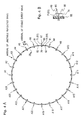
- the antenna is intended to enable such a ring-shaped array antenna as depicted in Fig.
- the flanges 81 and 82 are formed aslant in opposite directions at an angle ⁇ nearly equal to 7.5°.
- the flanges 81 and 82 are also given metal plating, and they have through holes 83 for joining means.
- a coaxial feeder line which has a characteristic impedance of, example, 50 ⁇ is formed by the through hole 68 serving as a center conductor and the outer conductor 71; the first and second antenna elements 65 and 66 form a half-wavelength dipole antenna; the reflector layer 74 forms a reflecting surface; and the slits 72 and 73 of the outer conductor 71, which are about ⁇ /4 long, form a balun (a balanced-to-unbalanced transformer).
- a dipole antenna is obtained which suppresses an unbalanced current. Since the through holes 76 formed by the small holes 75 are disposed around the feeding part 61 in close relation thereto, the through holes 76 serve as coaxial outer conductors in the reflector part 64, providing an excellent feeding part.
- the feeding part 61 In the manufacture of this antenna, the feeding part 61, as depicted in Fig. 3 , a mold is used such that the first and second antenna parts 62 and 63, the reflector part 64, the connector part 78, and the coupling flanges 81-82 are formed in one piece of a synthetic resin material which is excellent in high-frequency characteristic and highly heat-resistant.
- the outer diameter of the feeding part 61 near the reflector part 64 is larger than its outer diameter near the first and second antenna elements 62 and 63, and the cross-sectional areas of the first and second antenna elements 62 and 63 are gradually decreased with distance from the feeding part 61.
- the marginal portions of the first and second antenna elements 62 and 63 facing toward the reflector part 64 are tapered and their marginal portions on the opposite side from the reflector part 64 are parallel therewith.
- the molded structure is coated all over its surface with a metal-plated layer.
- the metal-plated layer is provided by depositing, for example, copper (Cu) to a thickness of around 10 ⁇ m, then nickel (Ni) to a thickness of 5 ⁇ m, and gold (Au) to a thickness of 1 ⁇ m or less.
- the gold coating is intended for corrosion resistance.
- Such a composition of the metal-plated layer provides a good affinity for the molding of the synthetic resin material.
- the metal-plated layer on the end face of the feeding part 61 adjoining the first and second antenna parts 62 and 63 is selectively removed at the marginal edge diametrically opposite the first antenna part 62 across the through hole 67 to form an exposed part 84, thereby providing the first and second antenna elements 65 and 66.
- the plated layer deposited over the outer peripheral surface of the feeding part 61 is selectively removed to form the slits 72 and 73 which extend from the exposed part 84 of the end face of the feeding part 61 toward the reflector part 64 and are diametrically opposite across the through hole 67.
- an S parameter S 11 of this antenna is measured by a network analyzer or the like, and the lengths of the slits 72 and 73 are adjusted so that dip frequencies take desired values. That is, the frequency characteristic of the parameter S 11 exhibits a dip at a resonance frequency f 2 and at a lower frequency f 1 as depicted in Fig. 5 .
- the frequency f 1 is an impedance matching point of the balun and the dipole antenna by the slits 72 and 73, and varies with the lengths of the slits 72 and 73. The more the frequency f 1 is spaced apart from the frequency f 2 , the wider the bandwidth of the antenna becomes but the higher the voltage standing wave ratio (VSWR).
- the frequency f 1 comes closer to f 2 .
- the lengths of the slits 72 and 73 are adjusted such that the frequency f 1 is, for example, 80% of the frequency f 2 , though it varies with the required value VSWR. Taking into account the specific inductive capacity of the material for the feeding part 61, the lengths of the slits 72 and 73 closer to ⁇ 0/(4 ⁇ r ), the frequency f 1 approaches f 2 - ( ⁇ 0: wavelength in free space)
- the angle ⁇ of each of the coupling flanges 81 and 82 is increased or decreased, depending on whether the number of antenna elements used is smaller or larger than 24.
- the angle ⁇ is zero, that is, the flanges 81 and 82 are parallel to the reflector part 64.
- the antenna can be made wide-band by making the first and second antenna elements 61 and 62 bow-shaped as depicted in Fig. 6 .
- the reflector part 64 and the reflector layer 74 may be omitted.
- the above-described dipole antenna and the array antenna using such dipole antennas can be applied to other apparatus as well as the radio hologram observation apparatus.
- the improved dipole antenna is manufactured by molding the antenna-forming parts in one piece, coating the molding with a metal-plated layer and removing a selected area of the layer--this permits mass production of antenna elements of close dimensional tolerances and hence of desired characteristics. Accordingly, the dipole antenna needs no additional working in the case of forming the array antenna.
- the dipole antenna of the present invention can be manufactured at low cost.
Landscapes
- Physics & Mathematics (AREA)
- General Physics & Mathematics (AREA)
- Variable-Direction Aerials And Aerial Arrays (AREA)
- Aerials With Secondary Devices (AREA)
Applications Claiming Priority (3)
| Application Number | Priority Date | Filing Date | Title |
|---|---|---|---|
| JP11033499A JP2000307329A (ja) | 1999-04-19 | 1999-04-19 | ダイポールアンテナ及びその製造方法 |
| JP16648599A JP3753296B2 (ja) | 1999-06-14 | 1999-06-14 | 電波ホログラム観測装置 |
| EP00108558A EP1046962A3 (fr) | 1999-04-19 | 2000-04-19 | Méthode et dispositif d'observation d'hologrammes en fréquence radio |
Related Parent Applications (1)
| Application Number | Title | Priority Date | Filing Date |
|---|---|---|---|
| EP00108558A Division EP1046962A3 (fr) | 1999-04-19 | 2000-04-19 | Méthode et dispositif d'observation d'hologrammes en fréquence radio |
Publications (2)
| Publication Number | Publication Date |
|---|---|
| EP1933209A2 true EP1933209A2 (fr) | 2008-06-18 |
| EP1933209A3 EP1933209A3 (fr) | 2008-07-16 |
Family
ID=26449981
Family Applications (2)
| Application Number | Title | Priority Date | Filing Date |
|---|---|---|---|
| EP08004541A Withdrawn EP1933209A3 (fr) | 1999-04-19 | 2000-04-19 | Antenne dipôle et son procédé de fabrication |
| EP00108558A Withdrawn EP1046962A3 (fr) | 1999-04-19 | 2000-04-19 | Méthode et dispositif d'observation d'hologrammes en fréquence radio |
Family Applications After (1)
| Application Number | Title | Priority Date | Filing Date |
|---|---|---|---|
| EP00108558A Withdrawn EP1046962A3 (fr) | 1999-04-19 | 2000-04-19 | Méthode et dispositif d'observation d'hologrammes en fréquence radio |
Country Status (2)
| Country | Link |
|---|---|
| US (2) | US6275181B1 (fr) |
| EP (2) | EP1933209A3 (fr) |
Cited By (1)
| Publication number | Priority date | Publication date | Assignee | Title |
|---|---|---|---|---|
| WO2011107597A1 (fr) * | 2010-03-04 | 2011-09-09 | Tdf | Structure antennaire à dipôles |
Families Citing this family (23)
| Publication number | Priority date | Publication date | Assignee | Title |
|---|---|---|---|---|
| EP1291972A1 (fr) * | 2001-08-30 | 2003-03-12 | S.O. Solo Enterprise Ltd. | Méthode et appareil pour la production d'hologrammes |
| EP1434300B1 (fr) * | 2002-12-23 | 2007-04-18 | HUBER & SUHNER AG | Antenne à large bande avec une pièce coulée en trois dimensions |
| GB0701090D0 (en) * | 2007-01-19 | 2007-02-28 | Plasma Antennas Ltd | A selectable beam antenna |
| JP5272004B2 (ja) * | 2007-07-24 | 2013-08-28 | トムソン ライセンシング | 多アンテナシステム給電デバイスおよびかかるデバイスを備える無線リンク端末 |
| JP5208547B2 (ja) * | 2008-03-19 | 2013-06-12 | 東京エレクトロン株式会社 | 電力合成器およびマイクロ波導入機構 |
| FR2942914A1 (fr) | 2009-03-06 | 2010-09-10 | Alcatel Lucent | Dispositif d'assemblage d'une antenne |
| TWI452861B (zh) * | 2010-10-08 | 2014-09-11 | Realtek Semiconductor Corp | 天線分集裝置與天線分集方法 |
| CA2814635C (fr) | 2010-10-15 | 2019-11-12 | The Invention Science Fund I, Llc | Antennes a diffusion a la surface a champs de rayonnement ajustables |
| US9385435B2 (en) | 2013-03-15 | 2016-07-05 | The Invention Science Fund I, Llc | Surface scattering antenna improvements |
| CN103259102A (zh) * | 2013-05-06 | 2013-08-21 | 重庆金美通信有限责任公司 | 一种全向覆盖的智能天线 |
| US9923271B2 (en) | 2013-10-21 | 2018-03-20 | Elwha Llc | Antenna system having at least two apertures facilitating reduction of interfering signals |
| US9935375B2 (en) | 2013-12-10 | 2018-04-03 | Elwha Llc | Surface scattering reflector antenna |
| US9871291B2 (en) | 2013-12-17 | 2018-01-16 | Elwha Llc | System wirelessly transferring power to a target device over a tested transmission pathway |
| US9843103B2 (en) | 2014-03-26 | 2017-12-12 | Elwha Llc | Methods and apparatus for controlling a surface scattering antenna array |
| US9882288B2 (en) | 2014-05-02 | 2018-01-30 | The Invention Science Fund I Llc | Slotted surface scattering antennas |
| US9853361B2 (en) | 2014-05-02 | 2017-12-26 | The Invention Science Fund I Llc | Surface scattering antennas with lumped elements |
| US10446903B2 (en) | 2014-05-02 | 2019-10-15 | The Invention Science Fund I, Llc | Curved surface scattering antennas |
| US10178560B2 (en) | 2015-06-15 | 2019-01-08 | The Invention Science Fund I Llc | Methods and systems for communication with beamforming antennas |
| US9985352B2 (en) * | 2016-04-21 | 2018-05-29 | The Boeing Company | Dynamically allocated broadband multi-tap antenna |
| US10361481B2 (en) | 2016-10-31 | 2019-07-23 | The Invention Science Fund I, Llc | Surface scattering antennas with frequency shifting for mutual coupling mitigation |
| US10948578B2 (en) * | 2018-10-10 | 2021-03-16 | International Business Machines Corporation | Distinguishing holographic objects from physical objects |
| JP7210408B2 (ja) * | 2019-09-13 | 2023-01-23 | 株式会社東芝 | 電子装置及び方法 |
| CN112635976B (zh) * | 2020-12-17 | 2023-06-30 | 中北大学 | 一种锯齿形偶极子5g基站天线单元 |
Family Cites Families (16)
| Publication number | Priority date | Publication date | Assignee | Title |
|---|---|---|---|---|
| US2462881A (en) * | 1943-10-25 | 1949-03-01 | John W Marchetti | Antenna |
| US2976534A (en) * | 1959-07-02 | 1961-03-21 | Kampinsky Abe | Circularly polarized antenna |
| US3681771A (en) * | 1970-03-23 | 1972-08-01 | Macdowell Associates Inc | Retroflector dipole antenna array and method of making |
| US3887923A (en) * | 1973-06-26 | 1975-06-03 | Us Navy | Radio-frequency holography |
| US3922683A (en) * | 1974-06-24 | 1975-11-25 | Hazeltine Corp | Three frequency band antenna |
| US4647942A (en) * | 1981-11-20 | 1987-03-03 | Western Geophysical Co. | Circularly polarized antenna for satellite positioning systems |
| WO1988006295A1 (fr) * | 1987-02-13 | 1988-08-25 | Mitsubishi Denki Kabushiki Kaisha | Radar holographique |
| US5216695A (en) * | 1991-06-14 | 1993-06-01 | Anro Engineering, Inc. | Short pulse microwave source with a high prf and low power drain |
| US5283590A (en) * | 1992-04-06 | 1994-02-01 | Trw Inc. | Antenna beam shaping by means of physical rotation of circularly polarized radiators |
| US5748156A (en) * | 1994-02-28 | 1998-05-05 | Chaparral Communications | High-performance antenna structure |
| JPH09153725A (ja) * | 1995-11-30 | 1997-06-10 | Advantest Corp | プローブアンテナ |
| IL123364A (en) * | 1997-02-20 | 2003-07-06 | Advantest Corp | Hologram observation method for three-dimensional wave source distribution, and stereoscopic directivity estimation method of antenna and wave distribution observation method based on hologram observation |
| US6111549A (en) * | 1997-03-27 | 2000-08-29 | Satloc, Inc. | Flexible circuit antenna and method of manufacture thereof |
| US6198539B1 (en) * | 1997-08-22 | 2001-03-06 | Advantest Corporation | Hologram observation method and hologram observation apparatus |
| US6188356B1 (en) * | 1998-05-12 | 2001-02-13 | Advantest Corporation | Radio monitoring method and apparatus |
| AUPP549598A0 (en) * | 1998-08-27 | 1998-09-17 | Alcatel Alsthom Compagnie Generale D'electricite | Dipole feed arrangement for a reflector antenna |
-
2000
- 2000-04-18 US US09/551,099 patent/US6275181B1/en not_active Expired - Fee Related
- 2000-04-19 EP EP08004541A patent/EP1933209A3/fr not_active Withdrawn
- 2000-04-19 EP EP00108558A patent/EP1046962A3/fr not_active Withdrawn
-
2001
- 2001-03-30 US US09/823,392 patent/US6400331B2/en not_active Expired - Fee Related
Cited By (2)
| Publication number | Priority date | Publication date | Assignee | Title |
|---|---|---|---|---|
| WO2011107597A1 (fr) * | 2010-03-04 | 2011-09-09 | Tdf | Structure antennaire à dipôles |
| FR2957194A1 (fr) * | 2010-03-04 | 2011-09-09 | Tdf | Structure antennaire a dipoles |
Also Published As
| Publication number | Publication date |
|---|---|
| US20010022561A1 (en) | 2001-09-20 |
| US6275181B1 (en) | 2001-08-14 |
| US6400331B2 (en) | 2002-06-04 |
| EP1046962A2 (fr) | 2000-10-25 |
| EP1933209A3 (fr) | 2008-07-16 |
| EP1046962A3 (fr) | 2002-05-08 |
Similar Documents
| Publication | Publication Date | Title |
|---|---|---|
| EP1933209A2 (fr) | Antenne dipôle et son procédé de fabrication | |
| JP3874279B2 (ja) | 導波管スロットアンテナ | |
| US6177911B1 (en) | Mobile radio antenna | |
| US5990848A (en) | Combined structure of a helical antenna and a dielectric plate | |
| US6690336B1 (en) | Antenna | |
| CN100490248C (zh) | 天线装置 | |
| DE69535431T2 (de) | Antenne | |
| EP0469741B1 (fr) | Appareil à radiofréquence | |
| KR100356196B1 (ko) | 2주파 대응 안테나 장치 및 이를 사용한 이동 통신기기 | |
| US20080136723A1 (en) | Slot antenna | |
| KR20010101766A (ko) | 200메가헤르쯔 이상의 주파수에 대한 헬리컬 안테나 | |
| US7518554B2 (en) | Antenna arrays and methods of making the same | |
| US20180076528A1 (en) | 3D Printed Miniaturized Quadrifilar Helix Antenna | |
| US8188934B2 (en) | Antenna structure and a method for its manufacture | |
| US8279128B2 (en) | Tapered slot antenna | |
| US20080186243A1 (en) | VSWR improvement for bicone antennas | |
| TWI382589B (zh) | 一介電負載式天線 | |
| KR101859179B1 (ko) | 소형 광대역 대수 주기 안테나 | |
| US7113148B2 (en) | Bifilar helical antenna | |
| KR100641290B1 (ko) | 변형된 접지면을 이용한 초광대역 프린티드 모노폴 안테나 | |
| JP2000307329A (ja) | ダイポールアンテナ及びその製造方法 | |
| CN100459284C (zh) | 天线装置 | |
| US20220132656A1 (en) | Wideband Antenna, In Particular For A Microwave Imaging System | |
| Brebels et al. | Technologies for integrated mm-Wave antennas | |
| JPH03166802A (ja) | マイクロストリップアンテナ |
Legal Events
| Date | Code | Title | Description |
|---|---|---|---|
| PUAI | Public reference made under article 153(3) epc to a published international application that has entered the european phase |
Free format text: ORIGINAL CODE: 0009012 |
|
| PUAL | Search report despatched |
Free format text: ORIGINAL CODE: 0009013 |
|
| 17P | Request for examination filed |
Effective date: 20080312 |
|
| AC | Divisional application: reference to earlier application |
Ref document number: 1046962 Country of ref document: EP Kind code of ref document: P |
|
| AK | Designated contracting states |
Kind code of ref document: A2 Designated state(s): DE FR GB |
|
| AK | Designated contracting states |
Kind code of ref document: A3 Designated state(s): DE FR GB |
|
| RIC1 | Information provided on ipc code assigned before grant |
Ipc: G03H 5/00 20060101AFI20080515BHEP Ipc: H01Q 1/38 20060101ALI20080606BHEP Ipc: H01Q 9/28 20060101ALI20080606BHEP Ipc: H01Q 9/16 20060101ALI20080606BHEP |
|
| 17Q | First examination report despatched |
Effective date: 20080903 |
|
| AKX | Designation fees paid |
Designated state(s): DE FR GB |
|
| STAA | Information on the status of an ep patent application or granted ep patent |
Free format text: STATUS: THE APPLICATION IS DEEMED TO BE WITHDRAWN |
|
| 18D | Application deemed to be withdrawn |
Effective date: 20090317 |