EP1933477A1 - Reseau d'acces a fibres optiques et procede associe de protection de communication - Google Patents
Reseau d'acces a fibres optiques et procede associe de protection de communication Download PDFInfo
- Publication number
- EP1933477A1 EP1933477A1 EP06775490A EP06775490A EP1933477A1 EP 1933477 A1 EP1933477 A1 EP 1933477A1 EP 06775490 A EP06775490 A EP 06775490A EP 06775490 A EP06775490 A EP 06775490A EP 1933477 A1 EP1933477 A1 EP 1933477A1
- Authority
- EP
- European Patent Office
- Prior art keywords
- optical
- optical fiber
- communication service
- user terminal
- wireless
- Prior art date
- Legal status (The legal status is an assumption and is not a legal conclusion. Google has not performed a legal analysis and makes no representation as to the accuracy of the status listed.)
- Granted
Links
Images


Classifications
-
- H—ELECTRICITY
- H04—ELECTRIC COMMUNICATION TECHNIQUE
- H04B—TRANSMISSION
- H04B10/00—Transmission systems employing electromagnetic waves other than radio-waves, e.g. infrared, visible or ultraviolet light, or employing corpuscular radiation, e.g. quantum communication
- H04B10/25—Arrangements specific to fibre transmission
-
- H—ELECTRICITY
- H04—ELECTRIC COMMUNICATION TECHNIQUE
- H04B—TRANSMISSION
- H04B10/00—Transmission systems employing electromagnetic waves other than radio-waves, e.g. infrared, visible or ultraviolet light, or employing corpuscular radiation, e.g. quantum communication
- H04B10/03—Arrangements for fault recovery
- H04B10/032—Arrangements for fault recovery using working and protection systems
-
- H—ELECTRICITY
- H04—ELECTRIC COMMUNICATION TECHNIQUE
- H04B—TRANSMISSION
- H04B10/00—Transmission systems employing electromagnetic waves other than radio-waves, e.g. infrared, visible or ultraviolet light, or employing corpuscular radiation, e.g. quantum communication
-
- H—ELECTRICITY
- H04—ELECTRIC COMMUNICATION TECHNIQUE
- H04J—MULTIPLEX COMMUNICATION
- H04J3/00—Time-division multiplex systems
- H04J3/02—Details
- H04J3/14—Monitoring arrangements
-
- H—ELECTRICITY
- H04—ELECTRIC COMMUNICATION TECHNIQUE
- H04J—MULTIPLEX COMMUNICATION
- H04J3/00—Time-division multiplex systems
- H04J3/16—Time-division multiplex systems in which the time allocation to individual channels within a transmission cycle is variable, e.g. to accommodate varying complexity of signals, to vary number of channels transmitted
- H04J3/1694—Allocation of channels in TDM/TDMA networks, e.g. distributed multiplexers
-
- H—ELECTRICITY
- H04—ELECTRIC COMMUNICATION TECHNIQUE
- H04W—WIRELESS COMMUNICATION NETWORKS
- H04W24/00—Supervisory, monitoring or testing arrangements
- H04W24/04—Arrangements for maintaining operational condition
-
- H—ELECTRICITY
- H04—ELECTRIC COMMUNICATION TECHNIQUE
- H04W—WIRELESS COMMUNICATION NETWORKS
- H04W88/00—Devices specially adapted for wireless communication networks, e.g. terminals, base stations or access point devices
- H04W88/08—Access point devices
Definitions
- the present invention relates to an optical fiber access network and communication protection method thereof and especially relates to an optical fiber access network which can provide the function of communication protection and provide wireless communication protection when the optical fiber breaks, and a communication protection method which can protect the communication service from influence.
- the optical fiber access network is the inevitable trend of optical fiber communication.
- the optical fiber access network normally has five sorts of topological structures as follows: single star topology, multi-star topology, tree topology, bus topology and ring topology.
- the former four sorts can be called star structure.
- the star network can save more optical fibers and optical receiving and sending modules, and the branch structure of it is easy for coverage. Therefore, the star structure is normally adopted in the optical fiber access network.
- the optical fiber line For protecting the normal work of communication service, the optical fiber line needs to be protected in the optical fiber access network.
- the protection manner of the optical fiber line between the optical line terminal and the optical network unit is as follows:
- the main subject of the present invention is to provide an optical fiber access network and a communication protection method thereof aiming at the above-mentioned defect existed in the 1+1 protection manner of the optical fiber access network and the reason and current situation that the protection to the optical fiber line between the optical branching divider and the optical network unit in the star topology optical fiber access network is deficient in practical use.
- the optical fiber access network and the method assemble the wireless communication system and optical fiber communication system so as to make the communication service of the optical fiber communication system obtain powerful insurance and effectively use the communication resource.
- the present invention adopts an optical fiber access network which comprises an optical fiber communication system which at least consists of an optical line terminal 1, an optical branching divider 2, a first optical network unit 3 and an user terminal integration access device 4.
- a work optical fiber 91 and a protection optical fiber 92 for protecting the line of said work optical fiber 91 are set between the optical line terminal 1 and the optical branching divider 2.
- Said optical fiber access network also comprises a wireless base station 5 which is connected with said optical branching divider 2 through a second optical network unit 6.
- Said wireless base station 5 wirelessly communicates with a wireless user terminal device 7.
- the wireless user terminal device 7 and said first optical network unit 3 are connected with a communication service switch device 8 for switching the communication line respectively.
- the communication service switch device 8 is connected with said user terminal integration access device 4.
- Said wireless user terminal device 7 further communicates with said first optical network unit 3.
- Said optical line terminal 1 is provided with a first detection module 11 for detecting the signal in the work optical fiber 91 and the protection optical fiber 92, and a network managing system 12 for managing the integrated services of said optical line terminal 1.
- Said first detection module 11 is connected with said network management system 12.
- Said first optical network unit 3 is provided with a second detection module 31 for detecting signals and a control module 32 for sending a switching control signal to said communication service switch device 8. Wherein, said second detection module 31 can be connected with said control module 32.
- Said communication service switch device 8 can be set in said the first optical network unit 3, that is to say said communication service switch device 8 can be put into said first optical network unit 3, i.e. said communication service switch device 8 is integrated with said first optical network unit 3.
- the optical fiber access network can provide protection in wireless manner for the communication service between the optical branching divider and the optical network unit.
- the second detection module 31 detects the amplitude, power and/or energy of the signal transmitting in the optical fiber communication system.
- the second detection module 31 detects that the amplitude, power and/or energy of the signal are lower than the preset threshold and considers that the signal is lost.
- the communication service switch device 8 switches the user terminal integration access device 4 to the wireless user terminal device 7 to make the communication service of the optical fiber communication system be switched to the wireless communication system.
- optical fiber communication is better than the wireless communication system in the aspect of transmitting rate and stability and so on, it is considered that the failure of being cut in the optical fiber is eliminated when the second detection module 31 detects that the amplitude, power and/or energy of the signal from branching divider 2 are higher than the preset threshold.
- the communication service switch device 8 switches the user terminal integration access device 4 to the first optical network unit 3 make the communication service be switched back to the optical fiber communication system.
- the present invention adopts the 1+1 protection manner to protect the optical fiber line between the optical line terminal and the optical branching divider in the optical fiber access network, and adopts the wireless communication system to protect the optical fiber line between the optical branching divider and the optical network unit in the star structure optical fiber access network at the same time, which not only meets the need of user to the unusable time of the network so as to ensure the fluency of the communication service of the user in the stat structure optical network and especially the group users, but also breaks through the restriction of the resource of the pipe and optical cable and reduces the cost of investment, operation and maintenance. It can also be used to quickly cover the communication area where there is no optical cable in wireless way.
- the wireless communication system can be used as the protection system of the optical fiber communication system so as to facilitate the implementation step by step and the utilization of the device.
- the present invention sets the wireless base station near the optical branching divider so as to reduce the requirement for the coverage scope of the wireless base station.
- the present invention adopts the wireless communication system which can dynamically allocate the bandwidth to protect the fiber access network. After the failure of being cut off in the access optical fiber happens, the bandwidth of the wireless communication system can be concentrated to the optical network unit influenced to protect the bandwidth need of the user. When there isn't any failure, it can provide the wireless access service for many users so as to increase the utilization rate of the bandwidth in the communication system and enrich the service provided.
- the main idea of the present invention is to bring in the wireless communication system to protect the optical fiber line between the optical branching divider 2 and the first optical network unit 3 in the star structure optical fiber access network.
- the optical fiber access network with protection comprises the optical fiber communication system, the wireless communication system, the second optical network unit 6, and the communication service switch device 8.
- the communication service switch device 8 switches the communication service from the optical fiber communication system to the wireless communication system when there is failure of being cut off in the optical fiber between the optical branching divider 2 and the first optical network unit 3 in the optical fiber communication system. Because the optical fiber communication is better than the wireless communication system at the aspect of transmitting rate and stability, etc, the communication service switch device 8 switches the communication service from the wireless communication system back to the optical fiber communication system after the failure of being cut off in the optical fiber is cleared.
- Fig. 1 is the system structure view of the optical fiber access network in accordance with the present invention.
- the optical fiber communication system at least comprises an optical line terminal 1, an optical branching divider 2, the first optical network unit 3 and an integration access device of user terminal 4.
- the optical line terminal 1 has an interface to the switching equipment, router and the optical branching divider 2 to communicate with the optical branching divider through the work fiber 91 and the protection optical fiber 92 which protects the line of the work fiber 91, and provide necessary means to transmit various communication services.
- a first detection module 11 for detecting the signal in the work fiber 91 and protection optical fiber 92 and a network managing system 12 for managing integrated services of the optical line terminal 1 are set in the optical line terminal 1.
- the first detection module 11 is connected with the network managing system12.
- the optical branching divider 2 provides the physical connection taking optical fiber as the transmission medium for the first optical network unit 3 and optical line terminal 1, makes the signal transmitted in optical fiber conduct power reallocation after being coupled in the coupling area.
- the first optical network unit 3 is connected with the communication service switch device 8 for switching the communication line by optical fibers.
- the first optical network unit 3 at least comprises a second detection module 31 for detecting signals, an alarm module 33 for producing an alarm message of signal loss when the second detection module 31 detects no signal, a control module 32 for sending a switch control signal to the communication service switch device 8, a service interface function module 34 for sending and receiving the message of the wireless user terminal device 7 and a power supply and maintenance management function module 35 for supplying power and managing integrated services to the first optical network unit 3.
- the second detection module 31 is connected with the alarm module and the power supply and maintenance management function module, and can also be connected with the control module 32. Specifically, amplitude, power and/or energy detection devices and so on can be adopted.
- the alarm module 33 is connected with the service interface function module 34 and can be integrated with the detection module 31.
- the service interface function module 34 is also connected with the power supply and maintenance management function module 35 and the communication service switch device 8, and is connected with the optical branching divider 2 and the wireless user terminal device 7.
- the control module 32 is communicated with the service interface function module 34 and the power supply and maintenance management function module 35.
- the wireless communication system comprises a wireless base station 5 and the wireless user terminal device 7, wherein the wireless base station 5 is set near the optical branching divider 2, communicates with the optical branching divider 2 through the second optical network unit 6, and wirelessly communicates with the wireless user terminal device 7 so as to accomplishing the wireless sending and receiving and the management of the wireless resource etc, which can be a point to point system or one point to several points system, for example, a WiMax system.
- the wireless user terminal device 7 is provided with a first optical network unit 3 and the interface of the user terminal integration access device 4.
- the wireless user terminal device 7 is connected with the communication service switch device 8 for switching the communication line, and is connected with said first optical network unit 3 for receiving the alarm message coming from the first optical network unit 3 and the communication service switched so as to realize the message transmission between the wireless base station 5 and the user terminal integration access device 4.
- Communication service switch device 8 is used to switch the communication line, wherein the wireless user terminal device 7 and the first optical network unit 3 are connected with the communication service switch device 8 respectively.
- the communication service switch device 8 is connected with the user terminal integration access device 4.
- the switch of the communication service switch device 8 is controlled by the control module 32 in the first optical network unit 3, which can be set independent to the first optical network unit 3 or in the first optical network unit 3, i.e. integrated with the communication service switch device 8.
- an electric switch, an optical switch, a photoelectric switch, a micro-mechanical switch or an optical waveguide switch and so on can be adopted.
- the second detection module 31 detects the signal transmitted in the work line.
- the communication service switch device 8 switches the communication service transmitted between the optical wiring network 2 and the first optical network unit 3 to the wireless communication system, i.e. switches the communication service from the optical fiber communication system to the wireless communication system.
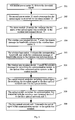
- Fig. 2 it is the specific processing flow of switching the communication service from the optical fiber communication system to the wireless communication system, and following steps are executed:
- the message of signal loss can also be directly sent to the control module 32 after the second power meter 31 detects that the downlink signal power is less than the preset threshold power.
- the control module 32 controls the switch to switch the communication service to the wireless communication system, i.e. the steps 202 ⁇ 206 can be omitted.
- the second power meter 31 in the first optical network unit 3 can detect the signal coming from the optical line terminal 1 after the failure of being cut off in the optical fiber between the optical wiring network 2 and the first optical network unit 3 is repaired.
- the communication service switch device 8 switches the communication service transmitted by the wireless communication system back to the optical fiber communication system, i.e. it switches the communication service from the wireless communication system back to the optical fiber communication system. As shown in Fig. 3 , it is the specific processing flow of switching the communication service from the wireless communication system back to the optical fiber communication system, and the following steps are executed:
- the message that the signal is received can be directly sent to the control module 32 after the second power rating meter 31 detects that the signal power is larger than the preset threshold power.
- the control module 32 controls the switch to switch the communication service to the optical fiber communication system, i.e. the steps 302 ⁇ 306 can be omitted.
Landscapes
- Engineering & Computer Science (AREA)
- Computer Networks & Wireless Communication (AREA)
- Signal Processing (AREA)
- Physics & Mathematics (AREA)
- Electromagnetism (AREA)
- Optical Communication System (AREA)
- Mobile Radio Communication Systems (AREA)
- Small-Scale Networks (AREA)
Applications Claiming Priority (2)
| Application Number | Priority Date | Filing Date | Title |
|---|---|---|---|
| CNB2005101025666A CN100385861C (zh) | 2005-09-12 | 2005-09-12 | 一种光纤接入网及其通信保护方法 |
| PCT/CN2006/002172 WO2007030999A1 (fr) | 2005-09-12 | 2006-08-24 | Reseau d'acces a fibres optiques et procede associe de protection de communication |
Publications (3)
| Publication Number | Publication Date |
|---|---|
| EP1933477A1 true EP1933477A1 (fr) | 2008-06-18 |
| EP1933477A4 EP1933477A4 (fr) | 2011-10-19 |
| EP1933477B1 EP1933477B1 (fr) | 2012-10-10 |
Family
ID=36748090
Family Applications (1)
| Application Number | Title | Priority Date | Filing Date |
|---|---|---|---|
| EP06775490A Active EP1933477B1 (fr) | 2005-09-12 | 2006-08-24 | Reseau d'acces a fibres optiques et procede associe de protection de communication |
Country Status (6)
| Country | Link |
|---|---|
| US (1) | US8160441B2 (fr) |
| EP (1) | EP1933477B1 (fr) |
| JP (1) | JP2009508373A (fr) |
| KR (1) | KR100946653B1 (fr) |
| CN (1) | CN100385861C (fr) |
| WO (1) | WO2007030999A1 (fr) |
Cited By (4)
| Publication number | Priority date | Publication date | Assignee | Title |
|---|---|---|---|---|
| WO2012128697A1 (fr) * | 2011-03-22 | 2012-09-27 | Telefonaktiebolaget L M Ericsson (Publ) | Onu avec capacité de connectivité sans fil |
| WO2013012538A1 (fr) * | 2011-07-18 | 2013-01-24 | Telefonaktiebolaget Lm Ericsson | Protection efficace en énergie et efficace en coût dans des réseaux optiques passifs |
| WO2014042570A1 (fr) * | 2012-09-14 | 2014-03-20 | Telefonaktiebolaget L M Ericsson (Publ) | Planification coopérative à base de qos pour gestion de trafic de données |
| CN114338427A (zh) * | 2022-03-02 | 2022-04-12 | 联信弘方(北京)科技股份有限公司 | 网络隐患分析方法、装置、电子设备和存储介质 |
Families Citing this family (28)
| Publication number | Priority date | Publication date | Assignee | Title |
|---|---|---|---|---|
| CN101047451B (zh) * | 2006-06-16 | 2010-12-01 | 华为技术有限公司 | 在线测量无源光网络性能参数的方法 |
| CN101170837B (zh) * | 2006-10-27 | 2010-08-18 | 中兴通讯股份有限公司 | 一种在吉比特无源光网络设备上实现跨线卡保护的方法 |
| CN101369938B (zh) * | 2007-08-16 | 2012-11-21 | 北京邮电大学 | 移动光网络 |
| CN101534153A (zh) * | 2008-03-12 | 2009-09-16 | 华为技术有限公司 | 一种中继器管理的方法、装置和系统 |
| CN101677415B (zh) * | 2008-09-19 | 2013-04-17 | 华为技术有限公司 | 光网络系统数据链路切换方法、光网络单元及系统 |
| US8155525B2 (en) * | 2009-05-15 | 2012-04-10 | Corning Cable Systems Llc | Power distribution devices, systems, and methods for radio-over-fiber (RoF) distributed communication |
| JP2010278620A (ja) * | 2009-05-27 | 2010-12-09 | Nippon Telegr & Teleph Corp <Ntt> | 光回線終端装置、故障箇所検出装置、通信経路切替方法、及び故障箇所検出方法 |
| CN101800599B (zh) * | 2010-02-10 | 2014-05-07 | 瑞斯康达科技发展股份有限公司 | 一种光纤线路保护设备及系统 |
| US9160449B2 (en) | 2010-10-13 | 2015-10-13 | Ccs Technology, Inc. | Local power management for remote antenna units in distributed antenna systems |
| US9252874B2 (en) | 2010-10-13 | 2016-02-02 | Ccs Technology, Inc | Power management for remote antenna units in distributed antenna systems |
| EP2643947B1 (fr) | 2010-11-24 | 2018-09-19 | Corning Optical Communications LLC | Module(s) de distribution d'énergie électrique capable(s) d'une connexion et/ou déconnexion à chaud pour des systèmes d'antennes réparties, et unités d'énergie électrique, composants et procédés associés |
| US11296504B2 (en) | 2010-11-24 | 2022-04-05 | Corning Optical Communications LLC | Power distribution module(s) capable of hot connection and/or disconnection for wireless communication systems, and related power units, components, and methods |
| CN102347832A (zh) * | 2011-08-18 | 2012-02-08 | 西南交通大学 | 一种简单拓扑结构的多信道混沌同步通信系统 |
| CN102355685B (zh) * | 2011-08-26 | 2014-07-02 | 新邮通信设备有限公司 | 链型组网下rru的复位方法和rru接入bbu的方法 |
| US9154222B2 (en) | 2012-07-31 | 2015-10-06 | Corning Optical Communications LLC | Cooling system control in distributed antenna systems |
| US10257056B2 (en) | 2012-11-28 | 2019-04-09 | Corning Optical Communications LLC | Power management for distributed communication systems, and related components, systems, and methods |
| EP3039814B1 (fr) | 2013-08-28 | 2018-02-21 | Corning Optical Communications Wireless Ltd. | Gestion de énergie pour des systèmes de communication distribués, et composants, systèmes et procédés associés |
| WO2015079435A1 (fr) | 2013-11-26 | 2015-06-04 | Corning Optical Communications Wireless Ltd. | Activation sélective des services de communication lors de la mise sous tension d'une ou plusieurs unités distantes dans un système d'antennes distribuées (das) basé sur la consommation d'énergie |
| US9785175B2 (en) | 2015-03-27 | 2017-10-10 | Corning Optical Communications Wireless, Ltd. | Combining power from electrically isolated power paths for powering remote units in a distributed antenna system(s) (DASs) |
| CN106253977B (zh) * | 2016-08-22 | 2019-05-21 | 青岛海信宽带多媒体技术有限公司 | Los告警判决门限的调整方法及光模块 |
| CN108173592B (zh) * | 2018-02-09 | 2024-01-30 | 深圳市慧通经纬智能科技股份有限公司 | 一种实现单机备纤调度功能的光纤测量仪 |
| CN108063460B (zh) * | 2018-01-03 | 2024-01-19 | 华北电力大学 | 能量管理系统及风电场 |
| CN110874090A (zh) * | 2018-09-04 | 2020-03-10 | 中国石油天然气股份有限公司 | 油气生产数据监控系统及方法 |
| JP7159752B2 (ja) * | 2018-09-26 | 2022-10-25 | 日本電気株式会社 | 送信機器、送信装置、送信機器の制御方法、および送信装置の制御方法 |
| CN110677279A (zh) * | 2019-09-11 | 2020-01-10 | 深圳市中燃科技有限公司 | 燃气监控方法、系统及计算机存储介质 |
| CN116170068B (zh) * | 2021-11-25 | 2024-08-27 | 中国联合网络通信集团有限公司 | 无线通信系统及采用其进行故障处理的方法和设备 |
| CN115334020A (zh) * | 2022-07-28 | 2022-11-11 | 深圳市普端科技有限公司 | 一种带有网络数据负载均衡的网络交换系统 |
| CN116233794A (zh) * | 2023-03-15 | 2023-06-06 | 马鞍山钢铁股份有限公司 | 一种基于5g技术实现企业铁路信号远程控制的系统及方法 |
Family Cites Families (20)
| Publication number | Priority date | Publication date | Assignee | Title |
|---|---|---|---|---|
| JP2569596B2 (ja) * | 1987-09-16 | 1997-01-08 | 日本電気株式会社 | ディジタル加入者線切替装置 |
| JPH03274928A (ja) * | 1990-03-26 | 1991-12-05 | Nippon Telegr & Teleph Corp <Ntt> | 通信方式 |
| US5982854A (en) * | 1996-02-23 | 1999-11-09 | Alcatel Usa, Inc. | Fiber optic based subscriber terminal |
| JP3510059B2 (ja) * | 1996-10-21 | 2004-03-22 | 富士通株式会社 | 交差型二重化構成を有するパッシブダブルスター通信システム |
| JPH11122172A (ja) * | 1997-10-20 | 1999-04-30 | Fujitsu Ltd | 光加入者ネットワークシステム |
| CN1142640C (zh) * | 1999-05-17 | 2004-03-17 | 华为技术有限公司 | 链形组网光纤传输网络的通信链路保护方法 |
| US6650630B1 (en) * | 1999-06-25 | 2003-11-18 | Telefonaktiebolaget Lm Ericsson (Publ) | Resource management and traffic control in time-division-duplex communication systems |
| JP2001057527A (ja) * | 1999-08-18 | 2001-02-27 | Toshiba Corp | 通信方法および通信装置 |
| US6650623B1 (en) * | 1999-12-30 | 2003-11-18 | Aperto Networks, Inc. | Adaptive link layer for point to multipoint communication system |
| US6763195B1 (en) * | 2000-01-13 | 2004-07-13 | Lightpointe Communications, Inc. | Hybrid wireless optical and radio frequency communication link |
| JP2001313660A (ja) * | 2000-02-21 | 2001-11-09 | Nippon Telegr & Teleph Corp <Ntt> | 波長多重光ネットワーク |
| US6895185B1 (en) * | 2000-08-24 | 2005-05-17 | Korea Advanced Institute Of Science And Technology | Multi-purpose optical fiber access network |
| JP3952677B2 (ja) * | 2000-09-26 | 2007-08-01 | 株式会社東芝 | 光伝送システム |
| JP2002190808A (ja) * | 2000-12-21 | 2002-07-05 | Tokyo Electric Power Co Inc:The | ループ状ケーブルを用いた無線lanシステム |
| JP2002280933A (ja) * | 2001-03-15 | 2002-09-27 | Mitsubishi Electric Corp | 通信局、通信切換方法および通信システム |
| US6889009B2 (en) * | 2001-04-16 | 2005-05-03 | Lightpointe Communications, Inc. | Integrated environmental control and management system for free-space optical communication systems |
| JP2003298605A (ja) * | 2002-04-04 | 2003-10-17 | Sumitomo Electric Ind Ltd | 通信路切替システム、及び、光ファイバ線路 |
| CN2703365Y (zh) | 2003-12-05 | 2005-06-01 | 中兴通讯股份有限公司 | 光纤线路保护装置 |
| JP4564745B2 (ja) * | 2003-12-15 | 2010-10-20 | ミハル通信株式会社 | Ftthシステムにおける入力切替え機能付き加入者用onu |
| US20060093356A1 (en) * | 2004-10-28 | 2006-05-04 | Vereen Jerry D | Optical network that detects and removes Rogue ONTS |
-
2005
- 2005-09-12 CN CNB2005101025666A patent/CN100385861C/zh not_active Expired - Lifetime
-
2006
- 2006-08-24 WO PCT/CN2006/002172 patent/WO2007030999A1/fr not_active Ceased
- 2006-08-24 JP JP2008529449A patent/JP2009508373A/ja active Pending
- 2006-08-24 US US12/066,087 patent/US8160441B2/en active Active
- 2006-08-24 KR KR1020087007650A patent/KR100946653B1/ko active Active
- 2006-08-24 EP EP06775490A patent/EP1933477B1/fr active Active
Cited By (7)
| Publication number | Priority date | Publication date | Assignee | Title |
|---|---|---|---|---|
| WO2012128697A1 (fr) * | 2011-03-22 | 2012-09-27 | Telefonaktiebolaget L M Ericsson (Publ) | Onu avec capacité de connectivité sans fil |
| CN103430465A (zh) * | 2011-03-22 | 2013-12-04 | 瑞典爱立信有限公司 | 具有无线连接能力的onu |
| WO2013012538A1 (fr) * | 2011-07-18 | 2013-01-24 | Telefonaktiebolaget Lm Ericsson | Protection efficace en énergie et efficace en coût dans des réseaux optiques passifs |
| US8554077B2 (en) | 2011-07-18 | 2013-10-08 | Telefonaktiebolaget L M Ericsson (Publ) | Energy efficiency and cost efficient protection in passive optical networks |
| WO2014042570A1 (fr) * | 2012-09-14 | 2014-03-20 | Telefonaktiebolaget L M Ericsson (Publ) | Planification coopérative à base de qos pour gestion de trafic de données |
| US10057847B2 (en) | 2012-09-14 | 2018-08-21 | Telefonaktiebolaget Lm Ericsson (Publ) | QOS-based cooperative scheduling for handling of data traffic |
| CN114338427A (zh) * | 2022-03-02 | 2022-04-12 | 联信弘方(北京)科技股份有限公司 | 网络隐患分析方法、装置、电子设备和存储介质 |
Also Published As
| Publication number | Publication date |
|---|---|
| EP1933477B1 (fr) | 2012-10-10 |
| CN100385861C (zh) | 2008-04-30 |
| WO2007030999A1 (fr) | 2007-03-22 |
| US8160441B2 (en) | 2012-04-17 |
| KR20080052620A (ko) | 2008-06-11 |
| KR100946653B1 (ko) | 2010-03-09 |
| CN1764123A (zh) | 2006-04-26 |
| JP2009508373A (ja) | 2009-02-26 |
| US20090148168A1 (en) | 2009-06-11 |
| EP1933477A4 (fr) | 2011-10-19 |
Similar Documents
| Publication | Publication Date | Title |
|---|---|---|
| US8160441B2 (en) | Optical fiber access network and commuication protection method thereof | |
| US10447343B2 (en) | System and method for controlling radio base station, and related device | |
| US7366120B2 (en) | Method and apparatus for improving quality of service over meshed bachaul facilities in a wireless network | |
| US7831145B2 (en) | Passive optical network system and method for protecting the services of the same | |
| CN103812710B (zh) | 电力通信专用通信终端 | |
| CN1082283A (zh) | 数字电信系统中的高速数据保护 | |
| CN110380810B (zh) | 一种半有源wdm波分系统 | |
| US8259708B2 (en) | Wireless access point network system supported through existing transmission lines | |
| EP0963629B1 (fr) | Procede et appareil pour assurer la disponibilite d'un service telephonique de secours sur un reseau hybride de lignes coaxiales et de fibres | |
| CN102082586A (zh) | 分布式基站链路系统及其链路保护方法 | |
| US6175552B1 (en) | Disaster recovery in a telecommunications network | |
| CN210183339U (zh) | 一种半有源wdm波分系统 | |
| CN100496002C (zh) | 光纤接入网及其通信保护方法 | |
| CN210093235U (zh) | 一种wdm的半有源olp的新系统 | |
| CN105933141B (zh) | 混合多端直流拓扑下站间通讯的组网方法 | |
| JP2020177765A (ja) | 通信機能を有する、非常灯装置及び非常灯システム | |
| JP2009088785A (ja) | 光アクセス網システム | |
| US20090016718A1 (en) | Wireless distribution of passive optical network signals | |
| JP2024044504A (ja) | 無線通信システム及び無線通信方法 | |
| CN202949423U (zh) | 一种光纤自动切换保护设备 | |
| JP2005191727A (ja) | Opgwシステム | |
| EP2234329A1 (fr) | Procédé et système de protection du canal partagé dans le système de transmission optique | |
| US20080089273A1 (en) | Wireless access point network system supported through existing transmission lines | |
| US7813641B1 (en) | Fiber optic cable topology for fiber optic repeater distributed antenna system | |
| JP2011211406A (ja) | 伝送装置、及び伝送経路の切替方法 |
Legal Events
| Date | Code | Title | Description |
|---|---|---|---|
| PUAI | Public reference made under article 153(3) epc to a published international application that has entered the european phase |
Free format text: ORIGINAL CODE: 0009012 |
|
| 17P | Request for examination filed |
Effective date: 20080311 |
|
| AK | Designated contracting states |
Kind code of ref document: A1 Designated state(s): AT BE BG CH CY CZ DE DK EE ES FI FR GB GR HU IE IS IT LI LT LU LV MC NL PL PT RO SE SI SK TR |
|
| A4 | Supplementary search report drawn up and despatched |
Effective date: 20110919 |
|
| RIC1 | Information provided on ipc code assigned before grant |
Ipc: H04B 10/12 20060101AFI20110913BHEP |
|
| DAX | Request for extension of the european patent (deleted) | ||
| GRAP | Despatch of communication of intention to grant a patent |
Free format text: ORIGINAL CODE: EPIDOSNIGR1 |
|
| GRAS | Grant fee paid |
Free format text: ORIGINAL CODE: EPIDOSNIGR3 |
|
| GRAA | (expected) grant |
Free format text: ORIGINAL CODE: 0009210 |
|
| AK | Designated contracting states |
Kind code of ref document: B1 Designated state(s): AT BE BG CH CY CZ DE DK EE ES FI FR GB GR HU IE IS IT LI LT LU LV MC NL PL PT RO SE SI SK TR |
|
| REG | Reference to a national code |
Ref country code: GB Ref legal event code: FG4D |
|
| REG | Reference to a national code |
Ref country code: AT Ref legal event code: REF Ref document number: 579356 Country of ref document: AT Kind code of ref document: T Effective date: 20121015 Ref country code: CH Ref legal event code: EP |
|
| REG | Reference to a national code |
Ref country code: IE Ref legal event code: FG4D |
|
| REG | Reference to a national code |
Ref country code: DE Ref legal event code: R096 Ref document number: 602006032414 Country of ref document: DE Effective date: 20121206 |
|
| REG | Reference to a national code |
Ref country code: NL Ref legal event code: T3 |
|
| PG25 | Lapsed in a contracting state [announced via postgrant information from national office to epo] |
Ref country code: SI Free format text: LAPSE BECAUSE OF FAILURE TO SUBMIT A TRANSLATION OF THE DESCRIPTION OR TO PAY THE FEE WITHIN THE PRESCRIBED TIME-LIMIT Effective date: 20121010 |
|
| REG | Reference to a national code |
Ref country code: AT Ref legal event code: MK05 Ref document number: 579356 Country of ref document: AT Kind code of ref document: T Effective date: 20121010 |
|
| REG | Reference to a national code |
Ref country code: LT Ref legal event code: MG4D |
|
| PG25 | Lapsed in a contracting state [announced via postgrant information from national office to epo] |
Ref country code: FI Free format text: LAPSE BECAUSE OF FAILURE TO SUBMIT A TRANSLATION OF THE DESCRIPTION OR TO PAY THE FEE WITHIN THE PRESCRIBED TIME-LIMIT Effective date: 20121010 Ref country code: LT Free format text: LAPSE BECAUSE OF FAILURE TO SUBMIT A TRANSLATION OF THE DESCRIPTION OR TO PAY THE FEE WITHIN THE PRESCRIBED TIME-LIMIT Effective date: 20121010 Ref country code: IS Free format text: LAPSE BECAUSE OF FAILURE TO SUBMIT A TRANSLATION OF THE DESCRIPTION OR TO PAY THE FEE WITHIN THE PRESCRIBED TIME-LIMIT Effective date: 20130210 Ref country code: SE Free format text: LAPSE BECAUSE OF FAILURE TO SUBMIT A TRANSLATION OF THE DESCRIPTION OR TO PAY THE FEE WITHIN THE PRESCRIBED TIME-LIMIT Effective date: 20121010 Ref country code: ES Free format text: LAPSE BECAUSE OF FAILURE TO SUBMIT A TRANSLATION OF THE DESCRIPTION OR TO PAY THE FEE WITHIN THE PRESCRIBED TIME-LIMIT Effective date: 20130121 |
|
| PG25 | Lapsed in a contracting state [announced via postgrant information from national office to epo] |
Ref country code: CY Free format text: LAPSE BECAUSE OF FAILURE TO SUBMIT A TRANSLATION OF THE DESCRIPTION OR TO PAY THE FEE WITHIN THE PRESCRIBED TIME-LIMIT Effective date: 20121010 Ref country code: PT Free format text: LAPSE BECAUSE OF FAILURE TO SUBMIT A TRANSLATION OF THE DESCRIPTION OR TO PAY THE FEE WITHIN THE PRESCRIBED TIME-LIMIT Effective date: 20130211 Ref country code: BE Free format text: LAPSE BECAUSE OF FAILURE TO SUBMIT A TRANSLATION OF THE DESCRIPTION OR TO PAY THE FEE WITHIN THE PRESCRIBED TIME-LIMIT Effective date: 20121010 Ref country code: LV Free format text: LAPSE BECAUSE OF FAILURE TO SUBMIT A TRANSLATION OF THE DESCRIPTION OR TO PAY THE FEE WITHIN THE PRESCRIBED TIME-LIMIT Effective date: 20121010 Ref country code: GR Free format text: LAPSE BECAUSE OF FAILURE TO SUBMIT A TRANSLATION OF THE DESCRIPTION OR TO PAY THE FEE WITHIN THE PRESCRIBED TIME-LIMIT Effective date: 20130111 Ref country code: PL Free format text: LAPSE BECAUSE OF FAILURE TO SUBMIT A TRANSLATION OF THE DESCRIPTION OR TO PAY THE FEE WITHIN THE PRESCRIBED TIME-LIMIT Effective date: 20121010 |
|
| PG25 | Lapsed in a contracting state [announced via postgrant information from national office to epo] |
Ref country code: AT Free format text: LAPSE BECAUSE OF FAILURE TO SUBMIT A TRANSLATION OF THE DESCRIPTION OR TO PAY THE FEE WITHIN THE PRESCRIBED TIME-LIMIT Effective date: 20121010 |
|
| PG25 | Lapsed in a contracting state [announced via postgrant information from national office to epo] |
Ref country code: DK Free format text: LAPSE BECAUSE OF FAILURE TO SUBMIT A TRANSLATION OF THE DESCRIPTION OR TO PAY THE FEE WITHIN THE PRESCRIBED TIME-LIMIT Effective date: 20121010 Ref country code: SK Free format text: LAPSE BECAUSE OF FAILURE TO SUBMIT A TRANSLATION OF THE DESCRIPTION OR TO PAY THE FEE WITHIN THE PRESCRIBED TIME-LIMIT Effective date: 20121010 Ref country code: EE Free format text: LAPSE BECAUSE OF FAILURE TO SUBMIT A TRANSLATION OF THE DESCRIPTION OR TO PAY THE FEE WITHIN THE PRESCRIBED TIME-LIMIT Effective date: 20121010 Ref country code: BG Free format text: LAPSE BECAUSE OF FAILURE TO SUBMIT A TRANSLATION OF THE DESCRIPTION OR TO PAY THE FEE WITHIN THE PRESCRIBED TIME-LIMIT Effective date: 20130110 Ref country code: CZ Free format text: LAPSE BECAUSE OF FAILURE TO SUBMIT A TRANSLATION OF THE DESCRIPTION OR TO PAY THE FEE WITHIN THE PRESCRIBED TIME-LIMIT Effective date: 20121010 |
|
| PLBE | No opposition filed within time limit |
Free format text: ORIGINAL CODE: 0009261 |
|
| STAA | Information on the status of an ep patent application or granted ep patent |
Free format text: STATUS: NO OPPOSITION FILED WITHIN TIME LIMIT |
|
| PG25 | Lapsed in a contracting state [announced via postgrant information from national office to epo] |
Ref country code: RO Free format text: LAPSE BECAUSE OF FAILURE TO SUBMIT A TRANSLATION OF THE DESCRIPTION OR TO PAY THE FEE WITHIN THE PRESCRIBED TIME-LIMIT Effective date: 20121010 Ref country code: IT Free format text: LAPSE BECAUSE OF FAILURE TO SUBMIT A TRANSLATION OF THE DESCRIPTION OR TO PAY THE FEE WITHIN THE PRESCRIBED TIME-LIMIT Effective date: 20121010 |
|
| 26N | No opposition filed |
Effective date: 20130711 |
|
| REG | Reference to a national code |
Ref country code: DE Ref legal event code: R097 Ref document number: 602006032414 Country of ref document: DE Effective date: 20130711 |
|
| REG | Reference to a national code |
Ref country code: CH Ref legal event code: PL |
|
| GBPC | Gb: european patent ceased through non-payment of renewal fee |
Effective date: 20130824 |
|
| PG25 | Lapsed in a contracting state [announced via postgrant information from national office to epo] |
Ref country code: CH Free format text: LAPSE BECAUSE OF NON-PAYMENT OF DUE FEES Effective date: 20130831 Ref country code: MC Free format text: LAPSE BECAUSE OF FAILURE TO SUBMIT A TRANSLATION OF THE DESCRIPTION OR TO PAY THE FEE WITHIN THE PRESCRIBED TIME-LIMIT Effective date: 20121010 Ref country code: LI Free format text: LAPSE BECAUSE OF NON-PAYMENT OF DUE FEES Effective date: 20130831 |
|
| REG | Reference to a national code |
Ref country code: IE Ref legal event code: MM4A |
|
| REG | Reference to a national code |
Ref country code: FR Ref legal event code: ST Effective date: 20140430 |
|
| PG25 | Lapsed in a contracting state [announced via postgrant information from national office to epo] |
Ref country code: IE Free format text: LAPSE BECAUSE OF NON-PAYMENT OF DUE FEES Effective date: 20130824 Ref country code: GB Free format text: LAPSE BECAUSE OF NON-PAYMENT OF DUE FEES Effective date: 20130824 |
|
| PG25 | Lapsed in a contracting state [announced via postgrant information from national office to epo] |
Ref country code: FR Free format text: LAPSE BECAUSE OF NON-PAYMENT OF DUE FEES Effective date: 20130902 |
|
| PG25 | Lapsed in a contracting state [announced via postgrant information from national office to epo] |
Ref country code: TR Free format text: LAPSE BECAUSE OF FAILURE TO SUBMIT A TRANSLATION OF THE DESCRIPTION OR TO PAY THE FEE WITHIN THE PRESCRIBED TIME-LIMIT Effective date: 20121010 |
|
| PG25 | Lapsed in a contracting state [announced via postgrant information from national office to epo] |
Ref country code: HU Free format text: LAPSE BECAUSE OF FAILURE TO SUBMIT A TRANSLATION OF THE DESCRIPTION OR TO PAY THE FEE WITHIN THE PRESCRIBED TIME-LIMIT; INVALID AB INITIO Effective date: 20060824 Ref country code: LU Free format text: LAPSE BECAUSE OF NON-PAYMENT OF DUE FEES Effective date: 20130824 |
|
| PGFP | Annual fee paid to national office [announced via postgrant information from national office to epo] |
Ref country code: NL Payment date: 20250826 Year of fee payment: 20 |
|
| PGFP | Annual fee paid to national office [announced via postgrant information from national office to epo] |
Ref country code: DE Payment date: 20250827 Year of fee payment: 20 |