EP1933488A1 - Empfänger, sendeverfahren und sendesystem - Google Patents
Empfänger, sendeverfahren und sendesystem Download PDFInfo
- Publication number
- EP1933488A1 EP1933488A1 EP06810223A EP06810223A EP1933488A1 EP 1933488 A1 EP1933488 A1 EP 1933488A1 EP 06810223 A EP06810223 A EP 06810223A EP 06810223 A EP06810223 A EP 06810223A EP 1933488 A1 EP1933488 A1 EP 1933488A1
- Authority
- EP
- European Patent Office
- Prior art keywords
- block
- inter
- interference component
- designates
- signal
- Prior art date
- Legal status (The legal status is an assumption and is not a legal conclusion. Google has not performed a legal analysis and makes no representation as to the accuracy of the status listed.)
- Withdrawn
Links
- 238000000034 method Methods 0.000 title claims description 27
- 238000012546 transfer Methods 0.000 claims abstract description 47
- 230000005540 biological transmission Effects 0.000 claims abstract description 32
- 239000013256 coordination polymer Substances 0.000 claims abstract description 20
- 239000011159 matrix material Substances 0.000 claims description 30
- 125000004122 cyclic group Chemical group 0.000 claims description 28
- 238000004364 calculation method Methods 0.000 claims description 15
- 101710094396 Hexon protein Proteins 0.000 claims description 8
- 238000010586 diagram Methods 0.000 description 6
- 238000000605 extraction Methods 0.000 description 6
- 238000004891 communication Methods 0.000 description 5
- 230000003111 delayed effect Effects 0.000 description 5
- 230000015572 biosynthetic process Effects 0.000 description 3
- 238000005516 engineering process Methods 0.000 description 3
- 238000013507 mapping Methods 0.000 description 3
- 238000003786 synthesis reaction Methods 0.000 description 3
- 238000004422 calculation algorithm Methods 0.000 description 2
- 108010076504 Protein Sorting Signals Proteins 0.000 description 1
- 238000012986 modification Methods 0.000 description 1
- 230000004048 modification Effects 0.000 description 1
- 238000012545 processing Methods 0.000 description 1
- 238000004088 simulation Methods 0.000 description 1
- 238000001228 spectrum Methods 0.000 description 1
Images


Classifications
-
- H—ELECTRICITY
- H04—ELECTRIC COMMUNICATION TECHNIQUE
- H04L—TRANSMISSION OF DIGITAL INFORMATION, e.g. TELEGRAPHIC COMMUNICATION
- H04L25/00—Baseband systems
- H04L25/02—Details ; arrangements for supplying electrical power along data transmission lines
- H04L25/03—Shaping networks in transmitter or receiver, e.g. adaptive shaping networks
- H04L25/03006—Arrangements for removing intersymbol interference
- H04L25/03012—Arrangements for removing intersymbol interference operating in the time domain
- H04L25/03019—Arrangements for removing intersymbol interference operating in the time domain adaptive, i.e. capable of adjustment during data reception
- H04L25/03057—Arrangements for removing intersymbol interference operating in the time domain adaptive, i.e. capable of adjustment during data reception with a recursive structure
-
- H—ELECTRICITY
- H04—ELECTRIC COMMUNICATION TECHNIQUE
- H04L—TRANSMISSION OF DIGITAL INFORMATION, e.g. TELEGRAPHIC COMMUNICATION
- H04L25/00—Baseband systems
- H04L25/02—Details ; arrangements for supplying electrical power along data transmission lines
- H04L25/03—Shaping networks in transmitter or receiver, e.g. adaptive shaping networks
- H04L25/03006—Arrangements for removing intersymbol interference
- H04L2025/0335—Arrangements for removing intersymbol interference characterised by the type of transmission
- H04L2025/03375—Passband transmission
- H04L2025/0342—QAM
-
- H—ELECTRICITY
- H04—ELECTRIC COMMUNICATION TECHNIQUE
- H04L—TRANSMISSION OF DIGITAL INFORMATION, e.g. TELEGRAPHIC COMMUNICATION
- H04L25/00—Baseband systems
- H04L25/02—Details ; arrangements for supplying electrical power along data transmission lines
- H04L25/03—Shaping networks in transmitter or receiver, e.g. adaptive shaping networks
- H04L25/03006—Arrangements for removing intersymbol interference
- H04L2025/03433—Arrangements for removing intersymbol interference characterised by equaliser structure
- H04L2025/03439—Fixed structures
- H04L2025/03445—Time domain
- H04L2025/03471—Tapped delay lines
- H04L2025/03484—Tapped delay lines time-recursive
- H04L2025/0349—Tapped delay lines time-recursive as a feedback filter
-
- H—ELECTRICITY
- H04—ELECTRIC COMMUNICATION TECHNIQUE
- H04L—TRANSMISSION OF DIGITAL INFORMATION, e.g. TELEGRAPHIC COMMUNICATION
- H04L25/00—Baseband systems
- H04L25/02—Details ; arrangements for supplying electrical power along data transmission lines
- H04L25/0202—Channel estimation
- H04L25/0212—Channel estimation of impulse response
- H04L25/0216—Channel estimation of impulse response with estimation of channel length
-
- H—ELECTRICITY
- H04—ELECTRIC COMMUNICATION TECHNIQUE
- H04L—TRANSMISSION OF DIGITAL INFORMATION, e.g. TELEGRAPHIC COMMUNICATION
- H04L27/00—Modulated-carrier systems
- H04L27/26—Systems using multi-frequency codes
- H04L27/2601—Multicarrier modulation systems
- H04L27/2602—Signal structure
- H04L27/261—Details of reference signals
- H04L27/2613—Structure of the reference signals
Definitions
- the present invention relates to a receiver, a transmission method and a transmission system and more preferably to a transmission system using a block in which a redundant signal such as a cyclic prefix (refer it to as a "CP", hereinafter) is inserted to avoid an inter-block interference from a previous block to a current block.
- a redundant signal such as a cyclic prefix (refer it to as a "CP", hereinafter) is inserted to avoid an inter-block interference from a previous block to a current block.
- a transmission system that transmits a block having the CP added to data (a transmitted signal) as shown in Fig. 2 .
- the CP is formed by copying the last K symbols of a data main body part (a useful block time) composed of M symbols before the data main body part.
- an OFDM (Orthogonal Frequency Division Multiplexing) system or a single carrier block transmission system with cyclic prefix (refer it to as a SC-CP, hereinafter) to which the cyclic prefix is applied is well-known.
- a received signal comes under an influence by a channel and a process for removing this influence in a receiver is referred to as an equalizing process.
- the equalizing process is ordinarily realized by a filter having performance inverse to the transfer function of the channel.
- an equalizer 100 of a discrete frequency domain is used in the block transmission system using the cyclic prefix (SC-CP).
- SC-CP cyclic prefix
- a received signal vector after the CP is removed is discrete Fourier transformed, multiplied by a weight for each frequency component in a transformed domain and returned again to a signal of a time domain by an inverse discrete Fourier transform to realize an equalization.
- Non-Patent Document 1 discloses that when a CP is added to a transmitted signal block, an inter-block interference can be removed by frequency domain equalizer (FDE) and a performance of it is improved.
- the inter-block interference (refer it also to as an "IBI", hereinafter) arises in such a way that a delayed signal of a previous block generated in the channel is overlapped on a signal of a current block.
- IBI frequency domain equalizer
- H 0 ⁇ h L ⁇ h 0 0 ⁇ 0 ⁇ ⁇ ⁇ ⁇ ⁇ ⁇ ⁇ ⁇ 0 ⁇ ⁇ ⁇ 0 h L ⁇ h 0
- Matrix size M + K ⁇ + 2 ⁇ M + K
- H is decomposed to two submatrices of (M+K)x (M+K), Equation 6
- H 1 0 ⁇ h L ⁇ h 1 ⁇ ⁇ ⁇ ⁇ ⁇ ⁇ h L ⁇ ⁇ 0 ⁇ ⁇ ⁇ 0
- H 0 h 0 ⁇ h 0 0 h L ⁇ ⁇ ⁇ 0 h L ⁇ h 0 the received signal block is expressed as described below.
- a first term of the right side of the equation (8) shows a signal component from a (n-1) th transmitting block and represents a component of the inter-block interference (IBI).
- IBI inter-block interference
- a matrix having such a structure as shown in the equation (12) is called a circulant matrix which can be transformed using a unitary similarity by a "discrete Fourier transform” (DFT) matrix.
- DFT discrete Fourier transform
- the equalizing process after the CP is removed is expressed by an equation as described below.
- the frequency domain equalizer uses discrete Fourier transform for the received signal block after the CP is removed, multiplies the received signal block by a weight for each frequency component in the frequency domain and returns again to a signal of a time domain by an inverse discrete Fourier transform.
- the discrete frequency domain weight is expressed as a diagonal matrix, whose diagonal element is ⁇ 0 , ..., ⁇ M-1 ⁇
- Non-Patent Document 1 discloses an equalizer weight of a zero forcing (ZF) criterion and an equalizer weight of a minimum mean-square-error(MMSE) criterion.
- ZF zero forcing
- MMSE minimum mean-square-error
- A denotes the diagonal matrix with diagonal element which is ⁇ 0 , whil, ⁇ M-1 ⁇ of the discrete Fourier transform of the impulse response of the channel obtained from the equation (14). Simulation examples using these weights are also disclosed in the Non-Patent Document 1 (Fig. 8).
- the MMSE criterion equalizer of the single carrier block transmission system is more excellent in its performance than the ZF criterion equalizer.
- a main reason why the ZF criterion equalizer is inferior to the MMSE criterion equalizer is a noise enhancement.
- the noise enhancement is a phenomenon that when a channel response of a communication path in a certain frequency i (0 ⁇ i ⁇ M-1) is 0 or near to 0, a weight in the frequency i shows a very large value so that noise is amplified.
- Non-Patent Document 1 Kazunori Hayashi “Fundamentals of Modulation/Demodulation and Equalization Technologies) Proc. MWE2004,pp. 523-532, 2004.
- the delayed signal of the previous block needs to remain within the CP of the current block and a situation must be avoided that the delayed signal of the previous block exceeds the CP of the current block.
- K ⁇ L needs to be established. That is, the length K of the CP needs to be equal to or larger than the order number L of the channel.
- the performance of the frequency domain equalizer suffers from IBI abruptly.
- the length K of the CP needs to be increased.
- a rate of the CP occupied in the block is increased and a rate of the useful block length is reduced and deteriorate a channel capacity.
- the present invention concerns a receiver for a transmission system using a block including a plurality of symbols.
- the receiver for a transmission system comprises: a transfer function estimating part that estimates a transfer function of a channel; and an inter-block interference component generating part that generates a replica of an inter-block interference component from a previous block to a current block in accordance with the transfer function estimated in the transfer function estimating part and a received signal of the previous block and is characterized in that the inter-block interference component of a received signal is reduced by using the replica of the inter-block interference component.
- the replica of the inter-block interference component is generated so that the inter-block interference component can be reduced, even when the order number of the channel is larger than the length of a redundant signal, an influence of the inter-block interference can be reduced.
- the block preferably has the redundant signal serving as a guard interval to the inter-block interference from the previous block to the current block. Further, the redundant signal preferably includes a cyclic prefix. The redundant signal may include other signal than the cyclic prefix.
- An equalizer is preferably provided that carries out a process for reducing, by the calculation of a prescribed equation, an interference component between the symbols generated depending on whether a cyclic prefix length is small or cyclic prefix does not exist, from the received signal in which the inter-block interference component is reduced.
- a received signal block after the inter-block interference component is reduced includes a new interference component between the symbols that cannot be satisfactorily equalized in the usual process explained in the background art.
- the interference component between the symbols can be reduced by the equalizer for reducing the interference component between the symbols.
- an inter-symbol interference component generating part is preferably provided that generates a replica of an interference component between the symbols in the current clock in accordance with the received signal in which the inter-block interference component is reduced and the estimated transfer function of the channel.
- the interference component between the symbols of the received signal is preferably reduced by using the replica of the interference component between the symbols.
- the inter-symbol interference component generating part preferably carries out a calculation by any one of equations (34) to (36) in a below-described embodiment to obtain a decided value as a transmitted signal block, which is used for generating the replica of the interference component between the symbols, from the received signal in which the inter-block interference component is reduced.
- equations (34) to (36) will be described in the below-described embodiment.
- the inter-symbol interference component generating part is preferably formed so as to generate the replica of the interference component between the symbols from the decided value as the transmitted signal block in accordance with equations (37) to (41) in the below-described embodiment. In this case, the calculation of signal processing can be faster and performances can be more improved.
- the receiver preferably includes an order number decision part that estimates the order number of the channel to decide whether or not the order number of the channel is larger than the length of the redundant signal. In this case, the receiver can grasp order number of the channel to carry out a proper process.
- the present invention concerns a transmission method that transmits a block including a plurality of symbols.
- the transmission method comprises a step of estimating a transfer function of a channel; a step of generating a replica of an inter-block interference component from a previous block to a current block in accordance with the estimated transfer function and a received signal of the previous block; and a step of reducing the inter-block interference component of a received signal by using the replica of the inter-block interference component.
- the present invention concerns a transmission system that transmits a block including a plurality of symbols from a transmitter and receives the block by a receiver.
- the receiver comprises: a transfer function estimating part that estimates a transfer function of a channel; and an inter-block interference component generating part that generates a replica of an inter-block interference component from a previous block to a current block in accordance with the transfer function estimated in the transfer function estimating part and a received signal of the previous block and is characterized in that the inter-block interference component of a received signal is reduced by using the replica of the inter-block interference component.
- Fig. 1 is a block diagram of a single carrier block transmission (SC-CP) system to which a cyclic prefix is applied.
- This transmission system includes a transmitter 10 and a receiver 20. A signal transmitted from the transmitter 10 is received by the receiver 20 via a channel 30.
- Fig. 2 shows a transmission data form in the transmission system.
- a preamble block illustrated in Fig. 3
- the data block (sometimes refer it to only as a block, hereinafter) is formed by adding a CP (K symbols) to a plurality of base band signals (M symbols).
- K symbols a CP
- M symbols base band signals
- the preamble block (sometimes refer it to only as a preamble, hereinafter) means a known signal added to the head part of the frame.
- the preamble block is used to estimate a frequency transfer function.
- the preamble block is used to take a synchronization of clock and carrier frequency in the receiver.
- PN Physical Random Noise
- the chirp signal is a "sine wave in which a frequency linearly increases" and a method for generating the chirp signal is described in Document [ J.Cioffi and J.A.C.Bingham, A Data-Driven Multitone Echo Canceller, IEEE Transactions on Communications, Vol. 42. No.10, P.2853-2869, 1994B, p.2866 ].
- the chirp signal has a merit that amplitude can be made to be fixed both in a time domain and a frequency domain.
- a pilot signal is a known signal embedded in a data block and used to estimate a frequency transfer function in the single carrier transmission system.
- the pilot signal is used to take a synchronization of clock and carrier frequency in the receiver.
- Fig. 3 of Document K. Hayashi and S. Hara, A New Spatio-Temporal Equalization Method Based on Estimated Channel Response, IEEE Transactions on Vehicular Technology, Vol. 50, No.5, p.1250-1259, 2001 .].
- a transmitted signal is divided into blocks at intervals of M symbols as shown in the above-described equation (1).
- the preamble block is also formed and added to the head part of the plurality of data blocks.
- the preamble block formed here also has a CP and the length Kp of the CP of the preamble is larger than the length K of the CP of the data block. Further, the length Kp of the CP of the preamble is set to be equal to or smaller than a length Mp of a known sequence of the preamble (MP ⁇ Kp ⁇ L > K).
- the length Kp of the CP of the preamble block is apt to be larger than the order number of the channel 30.
- the transfer function can be assuredly estimated in the receiver 20.
- the CP of the data block may be shorter than an ordinary length (smaller than the order number of the channel) to improve a channel capacity.
- the pilot signal is also formed and synthesized with a transmitted signal block. Further, the cyclic prefix (CP) is added that is formed by copying the last part of the block in the head part.
- CP cyclic prefix
- the receiver 20 receives the signal and demodulates the signal.
- the receiver 20 includes a transfer function estimating part 21 of the channel.
- the transfer function is estimated on the basis of a result obtained from a Fast Fourier transform (FFT) of the preamble or the pilot signal.
- FFT Fast Fourier transform
- the transfer function can be estimated only by the preamble in the head part of the frame, however, the estimated transfer function may be updated (corrected) by the pilot signal synthesized with the block, so that the transfer function of the channel changing dynamically can be more precisely estimated.
- the receiver 20 also includes an order number decision part 22 of the channel 30 to estimate the order number L of the channel 30.
- the order number L may be decided by the Fast Fourier transform (FFT) as in the transfer function estimating part 21 or by an order number deciding algorithm such as an AIC (Akaike Information Criterion) or a MDL (Minimum Description Length) algorithm.
- FFT Fast Fourier transform
- AIC Akaike Information Criterion
- MDL Minimum Description Length
- the estimated transfer function is supplied to an equalizer 23 for an equalizing process of a received signal. Further, when the order number L of the channel is larger than the length K of the CP (L > K), the estimated transfer function is also supplied to an inter-block interference component (IBI replica) generating part 24.
- IBI replica inter-block interference component
- the inter-block interference component generating part 24 generates, when L > K, an inter-block interference component (IBI replica) from a previous block to a current block.
- the IBI replica generated in the inter-block interference component generating part 24 is subtracted from the received signal r(n)(the current block) so that the inter-block interference (IBI) component can be reduced and a bit error rate can be improved.
- K ⁇ L a process for subtracting the replica of the inter-block interference component from the received signal r(n) is not carried out and the usual process described in the background art is carried out.
- the IBI replica is generated from the transfer function of the channel 30 supplied from the transfer function estimating part 21 and a decided value of a signal s(n-1) of the previous block.
- the decided signal of the previous block is obtained by an equalizing process of the equalizer 23, and is regarded as the transmitted signal s(n-1) of the previous block. It supplied to a next block by a one block delay part 25.
- a signal decision part 26 serves to determine a symbol by a prescribed criterion (a threshold value).
- n ( n ) R CP ⁇ ( n ).
- R CP H 0 T cp , R CP H 1 T cp , C, C ISI , and C IBI are respectively expressed as shown below.
- C h 0 0 ⁇ 0 0 0 0 0 0 0 0 0 0 0 0 0 0 0 0 ⁇ 0 0 ⁇ 0 h L
- C IBI s(n-1) designates the inter-block interference component from the previous block to the current block and C ISI s(n) designates an inter-symbol interference (ISI) component in the current block that is newly generated depending on whether the length of the cyclic prefix is short or the cyclic prefix does not exist.
- ISI inter-symbol interference
- the IBI component is reduced and the bit error rate can be improved.
- the ISI component is the inter-symbol interference or the interference between the symbols that is newly generated depending on whether the length of the cyclic prefix is short or the cyclic prefix does not exist.
- the equalizer 23 of this embodiment carries out a calculation of a below-described equation (26) to cancel the ISI component.
- D designates a DFT matrix expressed by the equation (15).
- ⁇ designates a diagonal matrix having ⁇ 0 , across, ⁇ M-1 ⁇ as diagonal elements and is given by below-described equations.
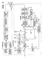
- Figs. 5 and 6 show a transmission system according to a second embodiment.
- a receiver 20 of this transmission system has a structure that an inter-symbol interference component generating part 27 for generating a replica of an inter-symbol interference component is added to the receiver 20 shown in Fig. 1 to add the replica of the inter-symbol interference component to a received signal in which the replica of an inter-block interference component is removed.
- the inter-symbol interference component generating part 27 includes an equalizer 27a and a signal decision part 27b similar to the equalizer 23 and the signal decision part 26 shown in Fig. 1 .
- a "temporarily decided" transmitted signal block is obtained from a received signal block after the replica of the inter-block interference component is removed by the equalizer 27a and the signal decision part 27b.
- the inter-symbol interference component generating part 27 has an ISI replica generating part 27c.
- This ISI replica generating part 27c generates the replica C ISI s(n) (ISI replica) of the inter-symbol interference component from the temporarily decided transmitted signal block to add the ISI replica to the received signal after the replica (IBI replica) of the inter-block interference component is removed.
- the received signal after the ISI replica is added is expressed as shown below.
- the equalizer 27a of the inter-symbol interference component generating part 27 has the same variations as some variations of calculating equations of the equalizing process in the equalizer 23 in Fig. 1 . That is, the equalizer 27a may carry out any of the calculations of the equation (26), the equation (27) or the equation (28). Further, the equalizer 27a may carry out the calculations of the equation (18) and the equation (19).
- ⁇ ( R CP H 0 T CP ) -1 r ( n ) ⁇ means a result obtained by deciding ( R CP H 0 T CP ) -1 r ( n ) in a demodulator.
- ⁇ . > indicates a decided result obtained by deciding a signal described in ⁇ > in the signal decision part (a demodulator) 27b as described above.
- the above-described thing is applied to below-described equations (35) and (36).
- ⁇ 0 , etc, ⁇ M-1 ⁇ is preferably given by the equations (29) to (32).
- C ISI s(n) may be simply calculated, however, in order to carry out the calculation at low complexity and improve performance, a structure shown in Fig. 6 is preferably provided to carry out the calculations of below-described equations (37) to (41).
- the below-described equation (37) is based on a matrix of C ISI shown in the equation (23) and means that an only submatrix (a specific submatrix G) shown by the below-described equation (38) may be enough to calculate and generate the ISI replica C ISI s(n), and all elements of s(n) is not required.
- the performance are improved. This is because the submatrix (the specific submatrix G) shown in the equation (38) does not comprise weak elements (M-L+1 to M-K th element) of s (n) (which is input of the ISI replica generating part 27c) suffered from the influence of the ISI, but strong elements (more definite elements) except the M-L+1 to M-K th elements.
Landscapes
- Engineering & Computer Science (AREA)
- Power Engineering (AREA)
- Computer Networks & Wireless Communication (AREA)
- Signal Processing (AREA)
- Cable Transmission Systems, Equalization Of Radio And Reduction Of Echo (AREA)
- Digital Transmission Methods That Use Modulated Carrier Waves (AREA)
Applications Claiming Priority (2)
| Application Number | Priority Date | Filing Date | Title |
|---|---|---|---|
| JP2005271081 | 2005-09-16 | ||
| PCT/JP2006/318431 WO2007032497A1 (ja) | 2005-09-16 | 2006-09-15 | 受信機、伝送方法、及び伝送システム |
Publications (1)
| Publication Number | Publication Date |
|---|---|
| EP1933488A1 true EP1933488A1 (de) | 2008-06-18 |
Family
ID=37865081
Family Applications (1)
| Application Number | Title | Priority Date | Filing Date |
|---|---|---|---|
| EP06810223A Withdrawn EP1933488A1 (de) | 2005-09-16 | 2006-09-15 | Empfänger, sendeverfahren und sendesystem |
Country Status (4)
| Country | Link |
|---|---|
| US (1) | US7953168B2 (de) |
| EP (1) | EP1933488A1 (de) |
| JP (1) | JPWO2007032497A1 (de) |
| WO (1) | WO2007032497A1 (de) |
Cited By (1)
| Publication number | Priority date | Publication date | Assignee | Title |
|---|---|---|---|---|
| US8462900B2 (en) | 2008-02-27 | 2013-06-11 | Panasonic Corporation | Reception device, integrated circuit, and reception method |
Families Citing this family (8)
| Publication number | Priority date | Publication date | Assignee | Title |
|---|---|---|---|---|
| JP4421635B2 (ja) * | 2007-06-18 | 2010-02-24 | 株式会社東芝 | 無線通信方法及び無線通信装置 |
| JP4461162B2 (ja) * | 2007-07-02 | 2010-05-12 | 株式会社東芝 | 端末装置 |
| GB2463872B (en) * | 2008-09-24 | 2012-04-18 | Toshiba Res Europ Ltd | A MMSE equaliser |
| US8611444B2 (en) * | 2011-06-22 | 2013-12-17 | Infomax Communication Co., Ltd. | Receiver and signal receiving method thereof |
| WO2016002106A1 (ja) | 2014-06-30 | 2016-01-07 | 日本電気株式会社 | 受信装置、受信方法及び非一時的なコンピュータ可読媒体 |
| US9326295B1 (en) | 2014-12-10 | 2016-04-26 | Sony Corporation | Method and apparatus for transmitting a-priori information in a communication system |
| US9455733B1 (en) * | 2015-03-30 | 2016-09-27 | Broadcom Corporation | System and method for spread spectrum ADC noise reduction |
| US11343666B2 (en) * | 2018-02-13 | 2022-05-24 | Qualcomm Incorporated | Waveform design of discovery signals |
Family Cites Families (5)
| Publication number | Priority date | Publication date | Assignee | Title |
|---|---|---|---|---|
| JP4298320B2 (ja) * | 2002-11-08 | 2009-07-15 | 富士通株式会社 | Ofdm伝送方式における受信装置 |
| JP4055587B2 (ja) * | 2003-01-27 | 2008-03-05 | 株式会社豊田中央研究所 | Ofdm復調方法及びofdm復調装置 |
| JP4311132B2 (ja) * | 2003-08-29 | 2009-08-12 | 富士通株式会社 | Ofdm伝送方式における受信装置 |
| JP4421416B2 (ja) * | 2004-08-04 | 2010-02-24 | 富士通株式会社 | Ofdm方式の受信装置 |
| US20060159187A1 (en) * | 2005-01-14 | 2006-07-20 | Haifeng Wang | System and method for utilizing different known guard intervals in single/multiple carrier communication systems |
-
2006
- 2006-09-15 EP EP06810223A patent/EP1933488A1/de not_active Withdrawn
- 2006-09-15 WO PCT/JP2006/318431 patent/WO2007032497A1/ja not_active Ceased
- 2006-09-15 JP JP2007535569A patent/JPWO2007032497A1/ja active Pending
- 2006-09-15 US US11/992,047 patent/US7953168B2/en not_active Expired - Fee Related
Non-Patent Citations (1)
| Title |
|---|
| See references of WO2007032497A1 * |
Cited By (1)
| Publication number | Priority date | Publication date | Assignee | Title |
|---|---|---|---|---|
| US8462900B2 (en) | 2008-02-27 | 2013-06-11 | Panasonic Corporation | Reception device, integrated circuit, and reception method |
Also Published As
| Publication number | Publication date |
|---|---|
| JPWO2007032497A1 (ja) | 2009-03-19 |
| US7953168B2 (en) | 2011-05-31 |
| WO2007032497A1 (ja) | 2007-03-22 |
| US20090268825A1 (en) | 2009-10-29 |
Similar Documents
| Publication | Publication Date | Title |
|---|---|---|
| KR100693778B1 (ko) | 트레이닝 프리픽스 변조 방법 및 수신기 | |
| EP1617611B1 (de) | Verfahren und Vorrichtung zur Übertragungspfadschätzung | |
| EP2120359B1 (de) | Kanalschätzungseinrichtung, entzerrungseinrichtung und entzerrungsverfahren bei der schätzung | |
| US8054917B2 (en) | Method and apparatus for advanced inter-carrier interference cancellation in orthogonal frequency division multiplexing (OFDM) channels | |
| EP2228955B1 (de) | Vorrichtung und Verfahren zum Empfang von OFDM-Signalen basierend auf Zeitbereichsfensterung in Anwesenheit vom Dopplereffekt | |
| US8824537B2 (en) | Signal processing in wireless communication receivers | |
| US12531771B2 (en) | Transmitter and receiver for, and method of, transmitting and receiving symbols over time varying channels with Doppler spread | |
| JPWO2017183631A1 (ja) | Los−mimo復調装置、通信装置、los−mimo伝送システム、los−mimo復調方法及びプログラム | |
| EP1933488A1 (de) | Empfänger, sendeverfahren und sendesystem | |
| JP2003218826A (ja) | 直交周波数分割多重信号の受信方式及び受信機 | |
| US7619964B2 (en) | High doppler channel estimation for OFD multiple antenna systems | |
| US8204465B2 (en) | Receiver, transmitter, transmission system, and transmission method | |
| US12107659B2 (en) | System and method for designing low-complexity linear receivers for OTFS system | |
| US8743946B2 (en) | Frequency-domain equalization and combining for single carrier transmission | |
| CN101133580A (zh) | 接收装置 | |
| WO2015101672A1 (en) | Methods and devices for doppler shift compensation in a mobile communication system | |
| US7864901B2 (en) | System, apparatus, and method for cancelling interferences of received signals | |
| JP2006245810A (ja) | 分数間隔等化器及びそれを用いた受信機 | |
| JP4501071B2 (ja) | シングルキャリアブロック伝送用受信機及び受信方法 | |
| JP2006246128A (ja) | フィルタリング方法および装置 | |
| KR100747593B1 (ko) | 직교주파수분할다중 기반 무선랜 수신기의 채널 추정 장치및 그 방법 | |
| Artai et al. | Determination of multipath channel parameters using wavelet decomposition | |
| Mohammadi et al. | MIMO filter-bank multicarrier system using unique word OFDM | |
| Wang et al. | Basis expansion model and doppler diversity techniques for frequency domain channel estimation and equalization in ds-cdma systems | |
| Wang et al. | On Frequency Domain Doppler Diversity Using Basis Expansion Model and EM-Based Algorithms in CDMA Systems |
Legal Events
| Date | Code | Title | Description |
|---|---|---|---|
| PUAI | Public reference made under article 153(3) epc to a published international application that has entered the european phase |
Free format text: ORIGINAL CODE: 0009012 |
|
| 17P | Request for examination filed |
Effective date: 20080327 |
|
| AK | Designated contracting states |
Kind code of ref document: A1 Designated state(s): DE FR GB |
|
| RBV | Designated contracting states (corrected) |
Designated state(s): DE FR GB |
|
| STAA | Information on the status of an ep patent application or granted ep patent |
Free format text: STATUS: THE APPLICATION HAS BEEN WITHDRAWN |
|
| 18W | Application withdrawn |
Effective date: 20110117 |