EP1933616B2 - Zitzengummi - Google Patents
Zitzengummi Download PDFInfo
- Publication number
- EP1933616B2 EP1933616B2 EP06779467.7A EP06779467A EP1933616B2 EP 1933616 B2 EP1933616 B2 EP 1933616B2 EP 06779467 A EP06779467 A EP 06779467A EP 1933616 B2 EP1933616 B2 EP 1933616B2
- Authority
- EP
- European Patent Office
- Prior art keywords
- liner
- teat cup
- shell
- check valve
- teat
- Prior art date
- Legal status (The legal status is an assumption and is not a legal conclusion. Google has not performed a legal analysis and makes no representation as to the accuracy of the status listed.)
- Active
Links
Images

Classifications
-
- A—HUMAN NECESSITIES
- A01—AGRICULTURE; FORESTRY; ANIMAL HUSBANDRY; HUNTING; TRAPPING; FISHING
- A01J—MANUFACTURE OF DAIRY PRODUCTS
- A01J7/00—Accessories for milking machines or devices
- A01J7/02—Accessories for milking machines or devices for cleaning or sanitising milking machines or devices
- A01J7/025—Teat cup cleaning, e.g. by rinse jetters or nozzles
-
- A—HUMAN NECESSITIES
- A01—AGRICULTURE; FORESTRY; ANIMAL HUSBANDRY; HUNTING; TRAPPING; FISHING
- A01J—MANUFACTURE OF DAIRY PRODUCTS
- A01J5/00—Milking machines or devices
- A01J5/04—Milking machines or devices with pneumatic manipulation of teats
- A01J5/08—Teat-cups with two chambers
-
- A—HUMAN NECESSITIES
- A01—AGRICULTURE; FORESTRY; ANIMAL HUSBANDRY; HUNTING; TRAPPING; FISHING
- A01J—MANUFACTURE OF DAIRY PRODUCTS
- A01J7/00—Accessories for milking machines or devices
- A01J7/04—Accessories for milking machines or devices for treatment of udders or teats, e.g. for cleaning
Definitions
- the present invention relates to teat cups for animal milking equipment and, more particularly, to such teat cups enabling the application of treatment fluids to animal's teats and the teat cups, post milking.
- milking equipment installed in a milking parlor comprises a milking point at each animal stall within the parlor.
- Each milking point includes a milking cluster of teat cups for connecting the equipment to the teats of an animal to be milked.
- each milking cluster has four teat cups.
- Each teat cup comprises a hollow shell supporting a flexible liner which has a barrel portion for engaging about a teat and, at its upper end, has a head portion with a mouth through which the teat is engaged with the barrel of the liner.
- the liner communicates with a flexible, short milk tube connected to a, so called, clawpiece of the cluster where the milk extracted from the animals teats is collected and delivered, via a flexible, long milk tube, to the collection vessel of the equipment.
- a vacuum is applied to the teat cups, via the long milk tube, the clawpiece and the short milk tubes, for the purposes of extracting milk from the teat cups.
- This vacuum also leaks between the barrel of the liner and the engaged teat and is applied to a void formed about the teat in the head of the liner in order to capture the cup on the teat.
- Milking is achieved by automatically and alternately applying vacuum and atmospheric pressure pulses to the space between the shell' and the liner of each teat cup in order to flex the liner and stimulate discharge of milk from the engaged teat. It is customary to apply these pneumatic pulses either simultaneously to the teat cups of a cluster or alternately to pairs of the teat cups.
- the clawpiece includes a distributor for distributing the pneumatic pulses to the individual teat cups, via flexible pneumatic lines or tubes.
- the milking cluster at the milking point is withdrawn from the animal's teats (commonly referred to as "take-off") such as by an automatic cluster remover and, in a cleansing cycle, the teat cups are flushed internally with disinfectant and water and are dried with compressed air preparatory to use on the next animal to be milked.
- take-off the animal's teats
- Each teat cup may be fitted with one or more injection nozzles for injecting treatment fluids into the heads of the liners, as described in my copending international application published under the number WO2005/043986 .
- the treatment fluid is fed to the injection nozzles via a distributor of the clawpiece and, upon take-off, the milking cluster is designed to enable the short milk tubes to fall away from the centreline of the cluster so that the teat cups are inverted and hang with their heads downwardly from the clawpiece. Flushing is performed with the teat cups in this inverted position. Consequently liquid can escape through the head portions of the teat cups.
- the short milk tubes are connected to the clawpiece via spigots which are designed to cause the short milk tubes to be shut off at the spigots when the teat cups fall into their inverted position, so as to avoid entry of treatment fluid into the clawpiece and downstream milk tubes, and consequent contamination of the harvested milk, when the teat cup is back flushed subsequent to the milking of an animal.
- the teat cups of each milking cluster are subjected to disinfecting and washing by a so-called "jetter" ready for use at the next milking period.
- the jetter is connected to sources of liquid disinfectant detergents and rinsing water and vacuum is applied to the teat cups of a cluster to draw said liquid from the jetter, whilst the teat cups are disposed in an inverted position.
- US-A-5161482 discloses the preamble of claim 1.
- the invention consists in a flexible teat cup liner according to claim 1.
- the nozzle means may comprise one or more individual nozzles.
- the nozzle means is formed together with the check valve as a unit which is mounted internally of the liner at or adjacent the head portion.
- the liner of a teat cup requires regular replacing and the installation of the nozzle means and check valve on the liner enables simple replacement of these devices with the liner.
- the check valve unit may comprise a moulded plastics body having a passageway at one end defining the nozzle means and arranged to discharge into the head portion of the liner and an inlet at its opposite end for receiving the adjacent end of the delivery tube.
- the body houses the check valve which may comprise a stainless steel valve ball biased against a seat about an inlet port connected to the body inlet in order normally to close the inlet, the valve seat on the outlet side of the inlet port being in fluid communication with the nozzle passageway.
- the check valve unit is an interference fit in a preformed cavity in the liner which is typically made from resilient plastics, synthetic resin or silicone.
- the delivery tube is preferably mounted internally of the shell of the teat cup and extends from an external inlet port or nipple on the shell adjacent the discharge end of the teat cup to the check valve at the head portion of the liner.
- the construction may be such that the inlet side of the check valve is engageable with the adjacent end of the delivery tube as the liner is fitted to the shell.
- the inlet side of the check valve may incorporate suitable sealing means, such as one or more O-ring seals, for sealing the adjacent end of the delivery tube to the inlet of the check valve.
- the shell is moulded from plastics material and the delivery tube, which may be stainless steel, is disposed in a groove moulded in an internal sidewall of the shell.
- the delivery tube is substantially housed within the wall of the shell so that the delivery tube does not interfere with the flexing motion of the liner whilst milking with consequent risk of contact between the liner and delivery tube.
- mounting the delivery tube internally of the shell has the advantage of avoiding the necessity of "handing" the teat cups of a milking cluster.
- the delivery tubes for teat cups on opposite sides of the cluster have been located in like positions relative to the clawpiece and milking pulse tubes so as to avoid entanglement of the tubes upon take-off and when the teat cups fall into their inverted positions.
- an internally mounted delivery tube With an internally mounted delivery tube, the risk of such entanglement is alleviated.
- the delivery tube is engaged in a groove formed along the inside wall of the shell.
- the teat cups of a cluster are fitted with injection nozzles for injecting treatment fluids into the heads of the liners
- the present invention is also used to exercise control over these problems and alleviate them by rating the return spring means of the check valve such that it opens in response to a predetermined pressure differential existing between the vacuum occurring in the head portion of the liner and air pressure in the delivery tube, for example, atmospheric air pressure, to admit air to the head portion of the liner and regulate the vacuum present within the head portion.
- the teat cup illustrated in the accompanying drawings is one of four similar teat cups of a milking cluster used for milking a cow and which is connected to milking equipment.
- Each teat cup 1 comprises a hollow generally cylindrical shell 2 supporting a flexible liner 3 in spaced relation with the shell.
- the liner has a cylindrical barrel portion 4 sealed to the shell adjacent the bottom, discharge end 5 and adjacent the top or head end 6 of the cup.
- the liner has a head portion 7 which engages, via a skirt portion 8, about the outside of the shell in order to seal the shell to the head end of the barrel, and which projects above the adjacent end of the shell.
- the head 7 of the liner is formed with a mouth 9 permitting access to the interior of the liner.
- the head of the liner is formed with an internal annular cavity 10 which, when an animal's teat is inserted into the cup through the mouth 9, forms a void or space 11 between the side of the teat and the head.
- the liner has a discharge passageway 12 communicating with a flexible, short milk tube 13 which connects the teat cup to a clawpiece (not shown) of the milking cluster and via which vacuum is applied to the inside of the liner for removing, from the cup, milk discharged by the teat during the milking cycle.
- the shell 2 may be moulded from rigid plastics material whilst the liner 3 may be moulded from resilient plastic, synthetic rubber or silicone.
- Integrally moulded with the shell is an inlet tube 14 for connecting the space 15 between the shell 2 and the liner 3, via the clawpiece, to a suitable source for alternately supplying vacuum pulses and venting the space 15 to atmosphere in order to cause the liner to flex against the teat and stimulate milking of an animal to which the teat cup is fitted.
- the inlet tube has a spigot 16 at its inlet end to which is attached a flexible pipe (not shown) coupling the inlet tube to the clawpiece.
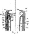
- a unit 17 comprising an injection nozzle component 18 for discharging into the cavity 10 in the head portion of the liner, a check valve assembly 19 for controlling delivery of fluid to the injection nozzle, and a coupling 20 for connecting a fluid delivery tube 21 to the unit.
- the latter comprises a body 22 moulded, for example, from plastics material and having a passageway 23 moulded at its upper end and defining an injection nozzle 24 which is configured so as to direct fluid discharged from the nozzle inwardly and downwardly into the interior of the barrel of the liner, as viewed in Figures 1 and 3 .
- the check valve assembly is an interference fit in the body 22 below the nozzle passageway 23 and comprises a springloaded valve ball 24 which is urged into contact with a valve seat 25 about an inlet port 26 of the valve by a spiral spring 27.
- the spiral spring is retained in position by a yoke construction 28 which, when the valve ball 24 is raised off its seat permits fluid to flow about the yoke to the nozzle passageway 23.
- the body below the inlet port, the body has a cavity 29 which houses O-ring seals 30 which are retained in the cavity by a cap member 31 which may be an interference fit in or bonded to the bottom end of the body 22.
- the cap member has a funnel shaped inlet opening 32 for receiving the adjacent end of the delivery tube 21 and, when the delivery tube is inserted through this inlet opening the O-rings seal the end of the delivery tube in the body 22.
- the unit 17 may be bonded to or be an interference fit in an aperture 33 in the liner on the inside of the head portion 7. It is prevented from moving upwardly in the head portion by a shoulder 34 adjacent the mouth of the liner and it is also indexed in predetermined alignment with the teat cup.
- the nozzle 24 is supplied with fluid, via the check valve 19, by the delivery tube 21 which is mounted internally of the shell 2 and connects a fluid inlet spigot 35 adjacent the discharge end 5 of the teat cup to the inlet of the unit body 22.
- the fluid inlet spigot 35 is moulded integrally with the shell juxtaposed and on the inside of the inlet passage 14. Downstream of the inlet spigot, the delivery tube snaps into a part-circular groove 36 moulded along the inside wall of the shell 2.
- the arrangement is such that the radial inner surface of the delivery tube is substantially flush with the inside surface of the shell so as not to interfere with the flexing motion of the liner 3 during milking.
- the delivery tube is conveniently moulded from stainless steel..
- a cylindrical weight 40 which assists in causing the lightweight plastic teat cups to fall into an inverted position with their heads downwardly upon take-off of the milking cluster
- the cylindrical weight 40 is preferably made from stainless steel and is sealed to the outside of the shell by O-rings 41 retained in annular grooves 42 moulded in the outside of the shell.
- the construction of the teat cup facilitates its assembly, and replacement of the liner 3 when necessary, and also, replacement of the cylindrical weight 40 to suit specific requirements of milking if more or less weight is required.
- the shell 2 is supplied with the delivery tube 21 mounted in the groove 36 along the inside of the shell.
- the appropriate cylindrical weight is mounted about the outside of the shell, over the O-rings 41 and against the moulded shoulder 39 and then the liner is assembled to the shell.
- the liner 3 is assembled by fitting the discharge end of the liner through the shell 2 from its head end.
- the adjacent end of the delivery tube 21 is automatically inserted into the inlet opening of the unit body 22 and is sealed to the body by the O-ring seals 30 housed in the body cavity 29.
- the inlet end 44 of the delivery tube may be chamfered to facilitate entry into the funnel shaped inlet opening 32 of the body.
- Sanitizing, rinsing and drying fluids such as disinfecting and conditioning liquid, water and compressed air are supplied to each milking point and milking cluster, from common sources, by a manifold system.
- a stall control unit incorporating solenoid operated valves selectively supplies the fluids from the manifold system to the teat cups via a distributor mounted on the clawpiece and flexible tubing (not shown) connecting the distributor to the fluid inlet spigots 35.
- the clawpiece Via the inlet tubes 14, the clawpiece also serves to distribute pneumatic milking pulses derived from suitable sources to the spaces 15 in the teat cups for milking purposes.
- an automatic cluster remover is signalled to take off the cluster from the cow's udder and, also, the equipment is signalled to commence the treatment and cleansing cycle.
- Disinfectant supplied through the delivery tubes 21, into the head portions 7, is firstly injected upon or immediately prior to actuation of the cluster remover so that, as the cups 1 are removed, disinfectant is discharged into each void 11 from the associated nozzle, spreads about the void and is wiped down the outside of each teat, thereby hygienically coating the whole teat with disinfecting liquid.
- the teat cups 1 naturally fall into an inverted position in which they hang downwardly from the short milk tubes, whereafter the control system is actuated so as, for example, sequentially to deliver pulses of water, disinfectant and compressed air to the nozzles 24 in order to sanitize and dry the teat cups.
- the control system is actuated so as, for example, sequentially to deliver pulses of water, disinfectant and compressed air to the nozzles 24 in order to sanitize and dry the teat cups.
- Such sanitizing of teats and teat cups is performed upon completion of the milking of each animal during a milking period.
- each cluster is thoroughly cleaned and disinfected on a jetter ready for use during the next milking period. Whilst being cleaned on the jetter, the check valve 19 prohibits dirt and cleaning fluid from entering and lodging in the fluid delivery tube.
- the check valve may also be used, during a milking cycle, to control the degree of vacuum applied to the head 7 of the liner by the vacuum used to withdraw, from the teat cup, milk discharged from the teat.
- the check valve can be arranged to open when the differential pressure between the vacuum in the cavity 11 and the air in the delivery tube 21 exceeds a predetermined amount so as to admit air to the head portion of the teat cup liner to regulate the vacuum.
Landscapes
- Life Sciences & Earth Sciences (AREA)
- Animal Husbandry (AREA)
- Environmental Sciences (AREA)
- Infusion, Injection, And Reservoir Apparatuses (AREA)
- Materials For Medical Uses (AREA)
- Table Devices Or Equipment (AREA)
- External Artificial Organs (AREA)
Claims (14)
- Flexible Zitzenbecherauskleidung (3), welche um eine Zitze eines Tieres, das gemolken werden soll, herum eingreift, wobei die Auskleidung einen Kopfabschnitt (7) an einem Ende (6), wobei er mit einem Mundstück (9) ausgestattet ist, durch welchen die Zitze mit der Auskleidung in Eingriff gelangt, und einen Milchausstoßkanal (12) am gegenüber liegenden Ende (5), ein Düsenmittel (24), welches angeordnet ist, um das Fluid in den Kopfabschnitt der Auskleidung auszustoßen, umfasst, und ein Rückschlagventil (19), durch welches das Düsenmittel (24) mit einem Fluidspeiserohr (21) verbindbar ist, wobei das Rückschlagventil so angeordnet ist, um Fluidanlieferung zum Düsenmittel zu gestatten, und im Kopfabschnitt (7) der Auskleidung (3) oder benachbart zu diesem eingebaut ist, dadurch gekennzeichnet, dass das Rückstellfedermittel (27) des Rückschlagventils (19) so bemessen ist, dass während des Melkvorgangs das Rückschlagventil so ausgelegt ist, um sich als Reaktion auf einen vorbestimmten Fluiddruckunterschied, welcher zwischen dem Vakuum, das im Kopfabschnitt (7) der Auskleidung (3) vorhanden ist, und dem Luftdruck, zum Beispiel atmosphärischer Luftdruck, im Speiserohr (21) zu öffnen, um Luft in den Kopfabschnitt der Auskleidung zuströmen zu lassen und das Vakuum, welches im Kopfabschnitt vorhanden ist, zu regulieren.
- Zitzenbecherauskleidung nach Anspruch 1, wobei das Düsenmittel gemeinsam mit dem Rückschlagventil (19) als eine Einheit (17) ausgebildet ist, welche innerhalb der Auskleidung (3) am Kopfabschnitt (7) oder benachbart dazu angebracht ist.
- Zitzenbecherauskleidung nach Anspruch 2, wobei die Einheit (17) einen Körper (22) umfasst, welcher einen Durchgang (23) and einem Ende aufweist, der das Düsenmittel (24) definiert und so angeordnet ist, um in den Kopfabschnitt (7) der Auskleidung (3) abzuleiten, und einen Einlass (32) an seinem gegenüber liegenden Ende zum Aufnehmen des benachbarten Endes (44) des Speiserohrs (21) aufweist, wobei das Rückschlagventil (19) zwischen dem Düsendurchgang (23) und dem Einlass (32) untergebracht ist.
- Zitzenbecherauskleidung nach Anspruch 2 oder 3, wobei die Einheit (17) eine Presspassung in einer Öffnung oder Ausnehmung (33) in der Auskleidung (3) aufweist.
- Zitzenbecherauskleidung nach Anspruch 1, 2, 3 oder 4, wobei das Rückschlagventil (19) ein Ventilelement (24) umfasst, welches gegen einen Sitz (25) um einen Einlassanschluss (26) herum vorgespannt ist, um normalerweise den Einlassanschluss zu schließen, wobei der Ventilsitz auf der Auslassseite des Einlassanschlusses (26) sich in Fluidverbindung mit dem Düsenmittel (24) befindet.
- Zitzenbecherauskleidung nach einem der vorangehenden Ansprüche, wobei das Rückschlagventil (19) Dichtmittel umfasst wie einen oder mehrere O-Ringdichtungen zum Abdichten des benachbarten Endes des Speiserohrs (21) zum Einlass des Rückschlagventils hin.
- Zitzenbecherauskleidung nach einem der vorangehenden Ansprüche, wobei das Düsenmittel (24) so konfiguriert ist, um das Fluid, welches davon ausgestoßen wird, in Richtung des Inneren des Schafts (4) der Auskleidung (3) zu lenken.
- Zitzenbecher, umfassend eine Auskleidung (3) nach einem der vorangehenden Ansprüche, welche durch ein Gehäuse (2) gestützt wird, und ein Speiserohr (21), welches innerhalb des Gehäuses angebracht ist und sich von einem äußeren Einlassanschluss oder Nippel (35) auf dem Gehäuse benachbart dem Ausstoßende (5) der Zitzenbecherauskleidung zum Rückschlagventil (19) am Kopfabschnitt der Auskleidung erstreckt.
- Zitzenbecher nach Anspruch 8, wobei das Rückschlagventil (19) in Eingriff mit dem benachbarten Ende des Speiserohrs (21) gebracht werden kann, wenn die Auskleidung (3) am Gehäuse (2) angebracht ist.
- Zitzenbecher nach Anspruch 8 oder 9, wobei das Speiserohr (21) in einer Vertiefung (36) angeordnet ist, welche an einer inneren Seitenwand des Gehäuses (2) ausgebildet ist.
- Zitzenbecher nach Anspruch 8, 9 oder 10, wobei das Gehäuse (2) aus einem Kunststoffmaterial gegossen ist.
- Zitzenbecher nach Anspruch 11, wobei der äußere Einlassanschluss für das Speiserohr (21) einen Einlassspundzapfen (35) umfasst, welcher einstückig mit dem Gehäuse (2) gegossen ist.
- Zitzenbecher nach einem der Ansprüche 8 bis 12, umfassend ein ringförmiges Gewicht (40), welches an der Außenseite des Kunststoffgehäuses (2) angebracht und/oder angeklebt ist, um den Zitzenbecher dabei zu unterstützen, in eine umgekehrte Position bei der Abnahme zu fallen.
- Zitzenbecherauskleidung nach Anspruch 13, wobei das ringförmige Gewicht (40) auf dem Gehäuse (2) benachbart zum Kopfabschnitt (7) der Auskleidung (3) angeordnet ist.
Priority Applications (1)
| Application Number | Priority Date | Filing Date | Title |
|---|---|---|---|
| PL06779467T PL1933616T5 (pl) | 2005-09-16 | 2006-09-15 | Kubek udojowy |
Applications Claiming Priority (2)
| Application Number | Priority Date | Filing Date | Title |
|---|---|---|---|
| GBGB0518976.6A GB0518976D0 (en) | 2005-09-16 | 2005-09-16 | Teat cup |
| PCT/GB2006/003455 WO2007031783A1 (en) | 2005-09-16 | 2006-09-15 | Teat cup |
Publications (3)
| Publication Number | Publication Date |
|---|---|
| EP1933616A1 EP1933616A1 (de) | 2008-06-25 |
| EP1933616B1 EP1933616B1 (de) | 2011-01-19 |
| EP1933616B2 true EP1933616B2 (de) | 2017-11-01 |
Family
ID=35248931
Family Applications (1)
| Application Number | Title | Priority Date | Filing Date |
|---|---|---|---|
| EP06779467.7A Active EP1933616B2 (de) | 2005-09-16 | 2006-09-15 | Zitzengummi |
Country Status (9)
| Country | Link |
|---|---|
| US (1) | US8210123B2 (de) |
| EP (1) | EP1933616B2 (de) |
| AT (1) | ATE495664T1 (de) |
| DE (1) | DE602006019750D1 (de) |
| DK (1) | DK1933616T4 (de) |
| ES (1) | ES2360078T5 (de) |
| GB (1) | GB0518976D0 (de) |
| PL (1) | PL1933616T5 (de) |
| WO (1) | WO2007031783A1 (de) |
Families Citing this family (27)
| Publication number | Priority date | Publication date | Assignee | Title |
|---|---|---|---|---|
| US8342125B2 (en) | 2004-06-12 | 2013-01-01 | Gea Farm Technologies, Inc. | Safety valve for an automatic dairy animal milker unit backflusher and teat dip applicator |
| US10874084B2 (en) | 2004-06-12 | 2020-12-29 | Gea Farm Technologies, Inc. | Safety valve for a dairy system component |
| US8025029B2 (en) | 2004-06-12 | 2011-09-27 | Gea Farm Technologies, Inc. | Automatic dairy animal milker unit backflusher and teat dip applicator system and method |
| US8117989B2 (en) * | 2008-06-27 | 2012-02-21 | Gea Farm Technologies, Inc. | Milk tube dome with flow controller |
| US8033247B2 (en) | 2004-06-12 | 2011-10-11 | Gea Farm Technologies, Inc. | Automatic dairy animal milker unit backflusher and teat dip applicator system and method |
| EP2355652B2 (de) | 2008-11-10 | 2021-03-17 | GEA Farm Technologies GmbH | Verfahren und Vorrichtung zum automatischen inkontaktbringen eines Fluids mit den Zitzen eines Tieres |
| US11723341B2 (en) | 2009-09-04 | 2023-08-15 | Gea Farm Technologies, Inc. | Safety valve for an automated milker unit backflushing and teat dip applicator system |
| AU2010290055B2 (en) * | 2009-09-04 | 2015-07-30 | Gea Farm Technologies, Inc. | Automatic dairy animal milker unit backflusher and teat dip applicator system and method |
| US8770146B2 (en) | 2009-09-04 | 2014-07-08 | Gea Farm Technologies, Inc. | Methods and apparatus for applying teat dip to a dairy animal |
| US8925483B2 (en) | 2010-02-22 | 2015-01-06 | Gea Farm Technologies, Inc. | Dairy harvesting facility with milk line protection system and methods |
| US20120097107A1 (en) | 2010-02-22 | 2012-04-26 | Gea Farm Technologies, Inc. | Dairy animal milking preparation system and methods |
| US8671884B2 (en) | 2011-04-27 | 2014-03-18 | Lanny Gehm | Milking machine attachment aid |
| ES2627989T3 (es) * | 2011-12-22 | 2017-08-01 | Delaval Holding Ab | Un cartucho y una pezonera |
| EP2838347A1 (de) * | 2012-04-18 | 2015-02-25 | DeLaval Holding AB | Lippenelement, melkbecherauskleidung und melkbecher |
| US9247708B2 (en) * | 2012-12-07 | 2016-02-02 | Lauren Agrisystems, Ltd. | Dairy milking devices and methods |
| CN104869810B (zh) * | 2012-12-19 | 2018-11-27 | 利拉伐控股有限公司 | 挤奶装置、一套可替换消耗部件及用于挤奶装置的方法 |
| JP6410799B2 (ja) * | 2013-05-02 | 2018-10-24 | デラヴァル ホルディング アーベー | 乳首カップ |
| US9526224B2 (en) | 2013-12-20 | 2016-12-27 | Gea Farm Technologies Gmbh | Safety valve device |
| DE102013114595B4 (de) | 2013-12-20 | 2026-01-15 | Gea Farm Technologies Gmbh | Sicherheitsventil |
| GB201405611D0 (en) * | 2014-03-28 | 2014-05-14 | An Udder Ip Company Ltd | A teat cup |
| JP2017079685A (ja) * | 2015-10-30 | 2017-05-18 | 株式会社アクト | 洗浄装置 |
| DE102016108300A1 (de) | 2016-05-04 | 2017-11-09 | Gea Farm Technologies Gmbh | Sicherheitsventil |
| DE102016215633B4 (de) * | 2016-08-19 | 2020-06-18 | Jakob Maier | Melkbecherhülse und modulares Melkbecherhülsensystem |
| GB2564489A (en) * | 2017-07-14 | 2019-01-16 | An Udder Ip Company Ltd | A milking cluster for milking an animal |
| BR112020007993B1 (pt) * | 2017-10-26 | 2024-01-02 | Delaval Holding Ab | Um conector para uma teteira a ser atada para a teta de um animal a ser ordenhado, e uma teteira |
| WO2019090136A1 (en) | 2017-11-03 | 2019-05-09 | Gea Farm Technologies, Inc. | Automated milking system safety valve arrangement |
| JP6621100B2 (ja) * | 2019-06-19 | 2019-12-18 | 株式会社アクト | 洗浄装置 |
Citations (4)
| Publication number | Priority date | Publication date | Assignee | Title |
|---|---|---|---|---|
| DE2622794A1 (de) † | 1976-05-21 | 1977-12-08 | Alfa Laval Agrar Gmbh | Verfahren und vorrichtung zur automatisierten anwendung von sanitisern an strichen und melkzeug |
| US5161482A (en) † | 1990-06-01 | 1992-11-10 | British Technology Group Limited | Automatic milking apparatus |
| EP0543463A1 (de) † | 1991-11-22 | 1993-05-26 | Alfa Laval Agrar GmbH | Melkvorrichtung und Zitzenbecher für diese Vorrichtung |
| WO1999066787A1 (en) † | 1998-06-22 | 1999-12-29 | Rieberjo B.V. | Milking device provided with cleansing means |
Family Cites Families (41)
| Publication number | Priority date | Publication date | Assignee | Title |
|---|---|---|---|---|
| US2532088A (en) | 1947-11-01 | 1950-11-28 | Cordis Nat | Cleansing apparatus |
| US3099246A (en) * | 1960-05-19 | 1963-07-30 | Separator Ab | Teat cup for milking machines |
| US3696790A (en) | 1970-01-08 | 1972-10-10 | Zero Manufacturing Co | Teat cup assembly |
| US3713423A (en) | 1971-01-08 | 1973-01-30 | A Sparr | Udder and teat cleansing apparatus and sanitizer |
| FR2419012A1 (fr) | 1978-03-08 | 1979-10-05 | Happel Fritz | Procede et dispositif de traite mecanique |
| US4332215A (en) | 1980-10-01 | 1982-06-01 | Hi-Life Rubber, Inc. | Milking inflation |
| US4393811A (en) * | 1981-03-24 | 1983-07-19 | Mae Lois Moore | Weighted teat cup shell and assembly |
| US4498419A (en) | 1982-10-18 | 1985-02-12 | Flocchini Andrew J | Backwash valve and system for teat cup assembly |
| US4516530A (en) | 1983-10-14 | 1985-05-14 | Germania Dairy Automation, Inc. | Milk sweep method and apparatus for automated milking systems |
| US4572105A (en) | 1984-09-20 | 1986-02-25 | Alfa-Laval, Inc. | Backflushing system |
| NL8700249A (nl) | 1987-02-02 | 1988-09-01 | Multinorm Bv | Werkwijze voor het reinigen van een tepel van een vrouwelijk dier, melkwerkwijze en beker ten gebruike bij bovengenoemde werkwijzen. |
| DD261300A1 (de) | 1987-05-28 | 1988-10-26 | Forschungszentrum F Mechani Si | Verfahren und vorrichtung zur zitzenreinigung und - nachdesinfektion sowie zur melkzeugzwischendesinfektion, insbesondere in automatisierten melkanlagen |
| GB9224405D0 (en) | 1992-11-20 | 1993-01-13 | Silsoe Research Inst | Cleaning of milking animal teats |
| NL9400241A (nl) | 1994-02-17 | 1995-10-02 | Prolion Bv | Besturingswijze voor een melkbehandelingssysteem en op deze wijze bestuurde melkinrichting. |
| US5493995A (en) * | 1994-05-16 | 1996-02-27 | Alfa Laval Agri, Inc. | Collapsing teat cup liner with tapering barrel wall |
| NL9500364A (nl) | 1995-02-24 | 1996-10-01 | Maasland Nv | Inrichting voor het melken van dieren. |
| EP0801893B1 (de) | 1996-04-17 | 2002-09-18 | Maasland N.V. | Gerät zum Melken von Tieren, sowie Kühen |
| US5850845A (en) | 1996-10-17 | 1998-12-22 | Pereira Construction, Inc. | Backflush valve for milking machine system |
| SE9704514D0 (sv) | 1997-12-04 | 1997-12-04 | Alfa Laval Agri Ab | Internal wings |
| SE9704515D0 (sv) | 1997-12-04 | 1997-12-04 | Alfa Laval Agri Ab | Combined cleaning and pre-milking device |
| NL1008673C2 (nl) | 1998-03-23 | 1999-09-24 | Maasland Nv | Inrichting en werkwijze voor het reinigen en/of desinfecteren van een speen van een dier. |
| SE514037C2 (sv) | 1998-08-31 | 2000-12-18 | Delaval Holding Ab | Förfarande och anordning för rengöring av spenarna hos ett mjölkdjurs juver |
| SE515440C2 (sv) | 1999-09-09 | 2001-08-06 | Delaval Holding Ab | Förfarande och anordning för att tvätta spenar hos ett djur |
| US6752102B2 (en) | 1999-09-27 | 2004-06-22 | Pro Chemicals, Llc | Apparatus for producing a foam bovine teat dip |
| SE515443C3 (sv) | 1999-12-15 | 2001-08-14 | Delaval Holding Ab | Förfarande och anordning för spenkoppstvättning |
| US6435132B1 (en) | 1999-12-23 | 2002-08-20 | Constance J. Milbrath | Teat cup assembly |
| US7290497B2 (en) | 2001-09-21 | 2007-11-06 | Westfaliasurge, Inc. | Milking device provided with cleansing means |
| NL1016237C2 (nl) | 2000-09-22 | 2002-03-25 | Rieberjo B V | Melkinrichting voorzien van reinigingsmiddelen. |
| DE10100840C2 (de) * | 2001-01-10 | 2003-01-30 | Westfalia Landtechnik Gmbh | Verfahren und Vorrichtung zum Melken |
| US20020185071A1 (en) | 2001-06-08 | 2002-12-12 | Fangjiang Guo | Apparatus for cleaning a teat of a dairy animal |
| SE0103367D0 (sv) | 2001-10-10 | 2001-10-10 | Delaval Holding Ab | A device and a method for treatment of a teat of an animal |
| US6755153B1 (en) | 2002-02-08 | 2004-06-29 | Mofazzal H. Chowdhury | Teatcup liner mouthpiece lip with controlled deflection and slip reduction |
| SE0201596D0 (sv) | 2002-05-29 | 2002-05-29 | Delaval Holding Ab | A device for cleaning the teats of an animal |
| US6997136B1 (en) | 2003-03-21 | 2006-02-14 | Avon Hi-Life, Inc. | Teat cup assembly |
| US6935270B2 (en) | 2003-08-29 | 2005-08-30 | Delaval, Inc. | Milking and application teat cup, system, and method |
| GB0408968D0 (en) | 2004-04-22 | 2004-05-26 | Duke James R J | Milking equipment |
| PL1790217T3 (pl) | 2003-10-22 | 2013-09-30 | An Udder Ip Company Ltd | Sprzęt udojowy |
| WO2005072516A1 (en) | 2004-01-30 | 2005-08-11 | James Richard John Duke | Milking equipment |
| US7401573B2 (en) * | 2004-06-12 | 2008-07-22 | Westfaliasurge, Inc. | Liner contact automatic teat dip applicator |
| NL1031749C2 (nl) | 2006-05-04 | 2007-11-06 | Jacob Hendrik Berthold Dietric | Melkklauwinrichting. |
| NL1031764C2 (nl) | 2006-05-08 | 2007-11-13 | Jacob Hendrik Berthold Dietric | Melkklauwinrichting eventueel met reinigingsfunctie. |
-
2005
- 2005-09-16 GB GBGB0518976.6A patent/GB0518976D0/en not_active Ceased
-
2006
- 2006-09-15 US US12/066,889 patent/US8210123B2/en active Active
- 2006-09-15 DK DK06779467.7T patent/DK1933616T4/en active
- 2006-09-15 WO PCT/GB2006/003455 patent/WO2007031783A1/en not_active Ceased
- 2006-09-15 PL PL06779467T patent/PL1933616T5/pl unknown
- 2006-09-15 ES ES06779467.7T patent/ES2360078T5/es active Active
- 2006-09-15 DE DE602006019750T patent/DE602006019750D1/de active Active
- 2006-09-15 EP EP06779467.7A patent/EP1933616B2/de active Active
- 2006-09-15 AT AT06779467T patent/ATE495664T1/de not_active IP Right Cessation
Patent Citations (4)
| Publication number | Priority date | Publication date | Assignee | Title |
|---|---|---|---|---|
| DE2622794A1 (de) † | 1976-05-21 | 1977-12-08 | Alfa Laval Agrar Gmbh | Verfahren und vorrichtung zur automatisierten anwendung von sanitisern an strichen und melkzeug |
| US5161482A (en) † | 1990-06-01 | 1992-11-10 | British Technology Group Limited | Automatic milking apparatus |
| EP0543463A1 (de) † | 1991-11-22 | 1993-05-26 | Alfa Laval Agrar GmbH | Melkvorrichtung und Zitzenbecher für diese Vorrichtung |
| WO1999066787A1 (en) † | 1998-06-22 | 1999-12-29 | Rieberjo B.V. | Milking device provided with cleansing means |
Also Published As
| Publication number | Publication date |
|---|---|
| ES2360078T3 (es) | 2011-05-31 |
| ES2360078T5 (es) | 2018-01-19 |
| PL1933616T5 (pl) | 2018-09-28 |
| PL1933616T3 (pl) | 2011-06-30 |
| WO2007031783A1 (en) | 2007-03-22 |
| DE602006019750D1 (de) | 2011-03-03 |
| ATE495664T1 (de) | 2011-02-15 |
| DK1933616T3 (da) | 2011-05-09 |
| EP1933616A1 (de) | 2008-06-25 |
| DK1933616T4 (en) | 2018-02-05 |
| US20080202433A1 (en) | 2008-08-28 |
| US8210123B2 (en) | 2012-07-03 |
| EP1933616B1 (de) | 2011-01-19 |
| GB0518976D0 (en) | 2005-10-26 |
Similar Documents
| Publication | Publication Date | Title |
|---|---|---|
| EP1933616B2 (de) | Zitzengummi | |
| US9016238B2 (en) | Milking equipment and method | |
| EP2625953B1 (de) | Zitzenreinigungsvorrichtung und entsprechendes Verfahren | |
| EP1890531B1 (de) | Automatischer zitzeneintauchapplikator mit zitzengummikontakt | |
| US8770146B2 (en) | Methods and apparatus for applying teat dip to a dairy animal | |
| EP2876996B1 (de) | Melkvorrichtung | |
| US10413915B2 (en) | Teat cup with nozzle means | |
| WO2005072516A1 (en) | Milking equipment | |
| EP2777387A1 (de) | Verfahren und Vorrichtung zur Anwendung eines Zitzenbades an einem Milchtier | |
| EP1744616A1 (de) | Melkvorrichtung und verbinderglied |
Legal Events
| Date | Code | Title | Description |
|---|---|---|---|
| PUAI | Public reference made under article 153(3) epc to a published international application that has entered the european phase |
Free format text: ORIGINAL CODE: 0009012 |
|
| 17P | Request for examination filed |
Effective date: 20080327 |
|
| AK | Designated contracting states |
Kind code of ref document: A1 Designated state(s): AT BE BG CH CY CZ DE DK EE ES FI FR GB GR HU IE IS IT LI LT LU LV MC NL PL PT RO SE SI SK TR |
|
| GRAP | Despatch of communication of intention to grant a patent |
Free format text: ORIGINAL CODE: EPIDOSNIGR1 |
|
| RAP1 | Party data changed (applicant data changed or rights of an application transferred) |
Owner name: AN UDDER IP COMPANY LTD |
|
| RIN1 | Information on inventor provided before grant (corrected) |
Inventor name: DUKE, JAMES RICHARD JOHN |
|
| DAX | Request for extension of the european patent (deleted) | ||
| GRAS | Grant fee paid |
Free format text: ORIGINAL CODE: EPIDOSNIGR3 |
|
| GRAA | (expected) grant |
Free format text: ORIGINAL CODE: 0009210 |
|
| AK | Designated contracting states |
Kind code of ref document: B1 Designated state(s): AT BE BG CH CY CZ DE DK EE ES FI FR GB GR HU IE IS IT LI LT LU LV MC NL PL PT RO SE SI SK TR |
|
| REG | Reference to a national code |
Ref country code: GB Ref legal event code: FG4D |
|
| 111L | Licence recorded |
Designated state(s): AT BE BG CH CY CZ DE DK EE ES FI FR GB GR HU IE IS IT LT LU LV MC NL PL PT RO SE SI SK TR Free format text: EXCLUSIVE LICENSE Name of requester: ADF MILKING LIMITED, GB Effective date: 20101018 |
|
| REG | Reference to a national code |
Ref country code: CH Ref legal event code: EP |
|
| REG | Reference to a national code |
Ref country code: IE Ref legal event code: FG4D |
|
| REF | Corresponds to: |
Ref document number: 602006019750 Country of ref document: DE Date of ref document: 20110303 Kind code of ref document: P |
|
| REG | Reference to a national code |
Ref country code: DE Ref legal event code: R096 Ref document number: 602006019750 Country of ref document: DE Effective date: 20110303 |
|
| REG | Reference to a national code |
Ref country code: NL Ref legal event code: T3 |
|
| REG | Reference to a national code |
Ref country code: DK Ref legal event code: T3 |
|
| REG | Reference to a national code |
Ref country code: ES Ref legal event code: FG2A Ref document number: 2360078 Country of ref document: ES Kind code of ref document: T3 Effective date: 20110531 |
|
| LTIE | Lt: invalidation of european patent or patent extension |
Effective date: 20110119 |
|
| REG | Reference to a national code |
Ref country code: PL Ref legal event code: T3 |
|
| PG25 | Lapsed in a contracting state [announced via postgrant information from national office to epo] |
Ref country code: SE Free format text: LAPSE BECAUSE OF FAILURE TO SUBMIT A TRANSLATION OF THE DESCRIPTION OR TO PAY THE FEE WITHIN THE PRESCRIBED TIME-LIMIT Effective date: 20110119 Ref country code: IS Free format text: LAPSE BECAUSE OF FAILURE TO SUBMIT A TRANSLATION OF THE DESCRIPTION OR TO PAY THE FEE WITHIN THE PRESCRIBED TIME-LIMIT Effective date: 20110519 Ref country code: GR Free format text: LAPSE BECAUSE OF FAILURE TO SUBMIT A TRANSLATION OF THE DESCRIPTION OR TO PAY THE FEE WITHIN THE PRESCRIBED TIME-LIMIT Effective date: 20110420 Ref country code: PT Free format text: LAPSE BECAUSE OF FAILURE TO SUBMIT A TRANSLATION OF THE DESCRIPTION OR TO PAY THE FEE WITHIN THE PRESCRIBED TIME-LIMIT Effective date: 20110519 Ref country code: LT Free format text: LAPSE BECAUSE OF FAILURE TO SUBMIT A TRANSLATION OF THE DESCRIPTION OR TO PAY THE FEE WITHIN THE PRESCRIBED TIME-LIMIT Effective date: 20110119 Ref country code: LV Free format text: LAPSE BECAUSE OF FAILURE TO SUBMIT A TRANSLATION OF THE DESCRIPTION OR TO PAY THE FEE WITHIN THE PRESCRIBED TIME-LIMIT Effective date: 20110119 |
|
| RAP2 | Party data changed (patent owner data changed or rights of a patent transferred) |
Owner name: AN UDDER IP COMPANY LTD |
|
| PG25 | Lapsed in a contracting state [announced via postgrant information from national office to epo] |
Ref country code: CY Free format text: LAPSE BECAUSE OF FAILURE TO SUBMIT A TRANSLATION OF THE DESCRIPTION OR TO PAY THE FEE WITHIN THE PRESCRIBED TIME-LIMIT Effective date: 20110119 Ref country code: SI Free format text: LAPSE BECAUSE OF FAILURE TO SUBMIT A TRANSLATION OF THE DESCRIPTION OR TO PAY THE FEE WITHIN THE PRESCRIBED TIME-LIMIT Effective date: 20110119 Ref country code: BG Free format text: LAPSE BECAUSE OF FAILURE TO SUBMIT A TRANSLATION OF THE DESCRIPTION OR TO PAY THE FEE WITHIN THE PRESCRIBED TIME-LIMIT Effective date: 20110419 Ref country code: BE Free format text: LAPSE BECAUSE OF FAILURE TO SUBMIT A TRANSLATION OF THE DESCRIPTION OR TO PAY THE FEE WITHIN THE PRESCRIBED TIME-LIMIT Effective date: 20110119 Ref country code: FI Free format text: LAPSE BECAUSE OF FAILURE TO SUBMIT A TRANSLATION OF THE DESCRIPTION OR TO PAY THE FEE WITHIN THE PRESCRIBED TIME-LIMIT Effective date: 20110119 Ref country code: AT Free format text: LAPSE BECAUSE OF FAILURE TO SUBMIT A TRANSLATION OF THE DESCRIPTION OR TO PAY THE FEE WITHIN THE PRESCRIBED TIME-LIMIT Effective date: 20110119 |
|
| PLBI | Opposition filed |
Free format text: ORIGINAL CODE: 0009260 |
|
| PG25 | Lapsed in a contracting state [announced via postgrant information from national office to epo] |
Ref country code: EE Free format text: LAPSE BECAUSE OF FAILURE TO SUBMIT A TRANSLATION OF THE DESCRIPTION OR TO PAY THE FEE WITHIN THE PRESCRIBED TIME-LIMIT Effective date: 20110119 |
|
| PLAX | Notice of opposition and request to file observation + time limit sent |
Free format text: ORIGINAL CODE: EPIDOSNOBS2 |
|
| 26 | Opposition filed |
Opponent name: DELAVAL INTERNATIONAL AB Effective date: 20111019 |
|
| PG25 | Lapsed in a contracting state [announced via postgrant information from national office to epo] |
Ref country code: RO Free format text: LAPSE BECAUSE OF FAILURE TO SUBMIT A TRANSLATION OF THE DESCRIPTION OR TO PAY THE FEE WITHIN THE PRESCRIBED TIME-LIMIT Effective date: 20110119 Ref country code: SK Free format text: LAPSE BECAUSE OF FAILURE TO SUBMIT A TRANSLATION OF THE DESCRIPTION OR TO PAY THE FEE WITHIN THE PRESCRIBED TIME-LIMIT Effective date: 20110119 Ref country code: CZ Free format text: LAPSE BECAUSE OF FAILURE TO SUBMIT A TRANSLATION OF THE DESCRIPTION OR TO PAY THE FEE WITHIN THE PRESCRIBED TIME-LIMIT Effective date: 20110119 |
|
| REG | Reference to a national code |
Ref country code: DE Ref legal event code: R026 Ref document number: 602006019750 Country of ref document: DE Effective date: 20111019 |
|
| PLBB | Reply of patent proprietor to notice(s) of opposition received |
Free format text: ORIGINAL CODE: EPIDOSNOBS3 |
|
| PG25 | Lapsed in a contracting state [announced via postgrant information from national office to epo] |
Ref country code: MC Free format text: LAPSE BECAUSE OF NON-PAYMENT OF DUE FEES Effective date: 20110930 |
|
| REG | Reference to a national code |
Ref country code: CH Ref legal event code: PL |
|
| PG25 | Lapsed in a contracting state [announced via postgrant information from national office to epo] |
Ref country code: LI Free format text: LAPSE BECAUSE OF NON-PAYMENT OF DUE FEES Effective date: 20110930 Ref country code: CH Free format text: LAPSE BECAUSE OF NON-PAYMENT OF DUE FEES Effective date: 20110930 |
|
| APBM | Appeal reference recorded |
Free format text: ORIGINAL CODE: EPIDOSNREFNO |
|
| APBP | Date of receipt of notice of appeal recorded |
Free format text: ORIGINAL CODE: EPIDOSNNOA2O |
|
| APAH | Appeal reference modified |
Free format text: ORIGINAL CODE: EPIDOSCREFNO |
|
| PLAB | Opposition data, opponent's data or that of the opponent's representative modified |
Free format text: ORIGINAL CODE: 0009299OPPO |
|
| R26 | Opposition filed (corrected) |
Opponent name: DELAVAL INTERNATIONAL AB Effective date: 20111019 |
|
| APBQ | Date of receipt of statement of grounds of appeal recorded |
Free format text: ORIGINAL CODE: EPIDOSNNOA3O |
|
| PG25 | Lapsed in a contracting state [announced via postgrant information from national office to epo] |
Ref country code: LU Free format text: LAPSE BECAUSE OF NON-PAYMENT OF DUE FEES Effective date: 20110915 |
|
| PG25 | Lapsed in a contracting state [announced via postgrant information from national office to epo] |
Ref country code: TR Free format text: LAPSE BECAUSE OF FAILURE TO SUBMIT A TRANSLATION OF THE DESCRIPTION OR TO PAY THE FEE WITHIN THE PRESCRIBED TIME-LIMIT Effective date: 20110119 |
|
| PG25 | Lapsed in a contracting state [announced via postgrant information from national office to epo] |
Ref country code: HU Free format text: LAPSE BECAUSE OF FAILURE TO SUBMIT A TRANSLATION OF THE DESCRIPTION OR TO PAY THE FEE WITHIN THE PRESCRIBED TIME-LIMIT Effective date: 20110119 |
|
| PLAB | Opposition data, opponent's data or that of the opponent's representative modified |
Free format text: ORIGINAL CODE: 0009299OPPO |
|
| R26 | Opposition filed (corrected) |
Opponent name: DELAVAL INTERNATIONAL AB Effective date: 20111019 |
|
| REG | Reference to a national code |
Ref country code: FR Ref legal event code: PLFP Year of fee payment: 11 |
|
| APBU | Appeal procedure closed |
Free format text: ORIGINAL CODE: EPIDOSNNOA9O |
|
| REG | Reference to a national code |
Ref country code: FR Ref legal event code: PLFP Year of fee payment: 12 |
|
| PUAH | Patent maintained in amended form |
Free format text: ORIGINAL CODE: 0009272 |
|
| STAA | Information on the status of an ep patent application or granted ep patent |
Free format text: STATUS: PATENT MAINTAINED AS AMENDED |
|
| 27A | Patent maintained in amended form |
Effective date: 20171101 |
|
| AK | Designated contracting states |
Kind code of ref document: B2 Designated state(s): AT BE BG CH CY CZ DE DK EE ES FI FR GB GR HU IE IS IT LI LT LU LV MC NL PL PT RO SE SI SK TR |
|
| REG | Reference to a national code |
Ref country code: DE Ref legal event code: R102 Ref document number: 602006019750 Country of ref document: DE |
|
| REG | Reference to a national code |
Ref country code: ES Ref legal event code: DC2A Ref document number: 2360078 Country of ref document: ES Kind code of ref document: T5 Effective date: 20180119 |
|
| REG | Reference to a national code |
Ref country code: DK Ref legal event code: T4 Effective date: 20180201 |
|
| REG | Reference to a national code |
Ref country code: NL Ref legal event code: FP |
|
| PG25 | Lapsed in a contracting state [announced via postgrant information from national office to epo] |
Ref country code: LV Free format text: LAPSE BECAUSE OF FAILURE TO SUBMIT A TRANSLATION OF THE DESCRIPTION OR TO PAY THE FEE WITHIN THE PRESCRIBED TIME-LIMIT Effective date: 20171101 |
|
| REG | Reference to a national code |
Ref country code: FR Ref legal event code: PLFP Year of fee payment: 13 |
|
| PGFP | Annual fee paid to national office [announced via postgrant information from national office to epo] |
Ref country code: GB Payment date: 20250930 Year of fee payment: 20 |
|
| PGFP | Annual fee paid to national office [announced via postgrant information from national office to epo] |
Ref country code: NL Payment date: 20251017 Year of fee payment: 20 |
|
| PGFP | Annual fee paid to national office [announced via postgrant information from national office to epo] |
Ref country code: DE Payment date: 20251020 Year of fee payment: 20 |
|
| PGFP | Annual fee paid to national office [announced via postgrant information from national office to epo] |
Ref country code: DK Payment date: 20251016 Year of fee payment: 20 Ref country code: IT Payment date: 20251031 Year of fee payment: 20 |
|
| PGFP | Annual fee paid to national office [announced via postgrant information from national office to epo] |
Ref country code: FR Payment date: 20251017 Year of fee payment: 20 |
|
| PGFP | Annual fee paid to national office [announced via postgrant information from national office to epo] |
Ref country code: IE Payment date: 20251021 Year of fee payment: 20 |
|
| PGFP | Annual fee paid to national office [announced via postgrant information from national office to epo] |
Ref country code: PL Payment date: 20251003 Year of fee payment: 20 |
|
| PGFP | Annual fee paid to national office [announced via postgrant information from national office to epo] |
Ref country code: ES Payment date: 20251020 Year of fee payment: 20 |