EP1933773B1 - Gerät zur neurochirurgisch-orthopädischen behandlung von pathologischen zuständen der menschlichen wirbelsäule - Google Patents
Gerät zur neurochirurgisch-orthopädischen behandlung von pathologischen zuständen der menschlichen wirbelsäule Download PDFInfo
- Publication number
- EP1933773B1 EP1933773B1 EP06779888A EP06779888A EP1933773B1 EP 1933773 B1 EP1933773 B1 EP 1933773B1 EP 06779888 A EP06779888 A EP 06779888A EP 06779888 A EP06779888 A EP 06779888A EP 1933773 B1 EP1933773 B1 EP 1933773B1
- Authority
- EP
- European Patent Office
- Prior art keywords
- spinal
- anyone
- pair
- channel
- contrast
- Prior art date
- Legal status (The legal status is an assumption and is not a legal conclusion. Google has not performed a legal analysis and makes no representation as to the accuracy of the status listed.)
- Not-in-force
Links
Images

Classifications
-
- A—HUMAN NECESSITIES
- A61—MEDICAL OR VETERINARY SCIENCE; HYGIENE
- A61B—DIAGNOSIS; SURGERY; IDENTIFICATION
- A61B17/00—Surgical instruments, devices or methods
- A61B17/56—Surgical instruments or methods for treatment of bones or joints; Devices specially adapted therefor
- A61B17/58—Surgical instruments or methods for treatment of bones or joints; Devices specially adapted therefor for osteosynthesis, e.g. bone plates, screws or setting implements
- A61B17/68—Internal fixation devices, including fasteners and spinal fixators, even if a part thereof projects from the skin
- A61B17/70—Spinal positioners or stabilisers, e.g. stabilisers comprising fluid filler in an implant
- A61B17/7062—Devices acting on, attached to, or simulating the effect of, vertebral processes, vertebral facets or ribs ; Tools for such devices
Definitions
- the present invention refer to an apparatus for the neurosurgical-orthopedic treatment of human spinal column pathologies, which is particularly, yet not exclusively, useful in treating the lumbar and cervical spinal stenosis.
- the lumbar and cervical stenosis is a pathology that affects the human being prevalently with advancing age.
- This pathology consists in a progressive reduction of the radicular inter-spinal channels existing between adjacent spinal processes of the spinal column in the lumbar, thorax and cervical region. This progressive reduction substantially reduces the space available for the passage of the blood vessels and nervous systems, leading to the following symptoms characteristic of this pathology:
- stenosis is treated in a first phase by applying non-invasive therapies such as medications, gymnastics and appropriate drugs.
- non-invasive therapies such as medications, gymnastics and appropriate drugs.
- a second phase it is necessary to take surgical action by implanting appropriate devices between adjacent spinal processes, which serve the purpose of enlarging and maintaining the enlarged shape of the damaged spinal channels.
- the subject affected by stenosis thus fully overcomes his pathological condition and recovers the normal functions associated with the spinal column.
- a first type of known apparatus is made in a single piece, formed of an elastically yielding material and presents a characteristic, approximately "H" shaped form.
- the central horizontal element of this apparatus operates as an elastically yielding contrast means to be fitted into an inter-spinal channel between a pair of adjacent spinal processes for the purpose of contrasting the stenosis of the channel.
- the vertical side elements of this apparatus act as constraining means associated to the contrast means to be bound to the adjacent spinal processes so as to hinder shifting motions of the contrast means outside/inside the inter-spinal channel.
- the implanting methodology of this first type of apparatus comprises a first phase of cutting the patient's rear ligament corresponding to the inter-spinal channel affected by the stenosis, and a second phase of emplacing the apparatus.
- the main drawback of this apparatus consists in the fact that its implantation is particularly invasive, because in attempting to resolve the patient's pathology it is necessary to take drastic action on a healthy organ of the same.
- the introduction of the central horizontal element into the inter-spinal channel in fact demands the cutting of the rear ligament before introducing the same.
- a second drawback of this device consists in the fact that the material employed for realizing this apparatus, generally a gel, tends to degrade in time and therefore to lose its mechanical features in time. This fact occasions numerous problems associated with the need of replacing the apparatus at regular, approximately pre-established time intervals.
- a second known apparatus is essentially formed in two mutually coupled pieces made of a rigid material.
- this apparatus defines a rigid contrast means to be fitted into an inter-spinal channel between a pair of adjacent spinal processes, so as to contrast the stenosis of the channel, and constraining means associated with the contrast means to keep the contrast means from shifting outside/inside the inter-spinal channel.
- this apparatus is composed of a first piece formed by the contrast means and first constraining means and by a second means formed in turn by second constraining means.
- the implanting methodology of this second type of apparatus comprises a first place of emplacing the first piece of the apparatus on one side of the column, a second phase of emplacing the second piece of the apparatus on the other side of the column corresponding to the first piece, and a third phase of mutually coupling the two pieces.
- the main drawback of this second type of apparatus consists in the fact that the contrast means provides no form of elastic reaction to the stresses the spinal processes are subjected to. This fact leads to abnormal stresses on the spinal processes.
- patent application US 2002/0120335 A1 discloses an implant for maintaining a distance between cut spinal bones.
- the implant has hollow regions for packing osteogenic material.
- the implant ends have surface projections to reduce slippage.
- Implants made of bone allograft also have spine contacting ends made of demineralized bone to speed fusion of spine and implant; they may also have bone flaps to fix the implant to the spine.
- a disadvantage with the apparatuses known from the state of the art, is that they have not elastic properties and also they provide complex assembling.
- the aim of the present invention is to achieve an apparatus for the neurosurgical-orthopedic treatment of human spinal column pathologies capable of resolving the mentioned drawbacks.
- an object of the invention consists in setting up an apparatus capable of developing a graduated contrast reaction against the stenosis of the channel receiving such apparatus.
- a further object of the invention is to set up an apparatus wherein said graduated contrast reaction is mainly induced by the shape of the elastically yielding contrast means.
- Another object of the invention is to set up an apparatus whose contrast reaction is enduring.
- the last object of the invention consists in setting up an apapratus easy to use on the whole and flexible to employ, so as to ease the implaning operations.
- the elastically yielding contrast means is formed by distancing means which distance a pair of adjacent spinal processes and by elastically yielding connecting means which connect the distancing means, so as to achieve a graduated contrast reaction against the stenosis of the channel the apparatus is applied to.
- the distancing means are made of a pair of wings and the elastically yielding connecting means are constituted of an extension common to said distancing means, so that on the whole the wings and the extension form a "C" shaped body that represents a form suitable for performing said graduated elastic reaction.
- said "C" shaped body can be made of a metallic or alloy material to guarantee an enduring reaction.
- the apparatus is in the overall characterized by the fact of being easy to use and flexible to apply, so as to substantially ease the implantation.
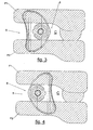
- the apparatus for the neurosurgical-orthopedic treatment of human spinal column pathologies is indicated as a whole by the reference number 5.
- This apparatus 5 comprises an elastically yielding contrast means indicated by the reference number 6.
- This contrast means 6 is fitted inside an inter-spinal channel C between a pair of spinal processes P1 and P2 for the purpose of contrasting the stenosis of the channel C.
- the apparatus further comprises constraining means designated as a whole by the reference number 7, associated with the contrast means 6.
- These contrast means 7 are constrained to the spinal processes P1 and P2, so as to impede shifting motions of the contrast means 6 outside/inside the inter-spinal channel C.
- the contrast means is in turn constituted of distancing means, indicated as a whole by the reference number 8, which serve the purpose of distancing the pair of spinal processes P1 and P2 and by elastically yielding connecting means, indicated as a whole by the reference number 9, which have the function of connecting the mentioned distancing means 8.
- distancing means 8 and the connecting means 9 achieve a contrast reaction graduated to the stenosis of the channel C.
- These distancing means 8 are appropriately disposed facing each other and placed in contact with the spinal processes P1 and P2.
- said distancing means 8 are constituted of a pair of wings designated by the reference numbers 10 and 11.
- the connecting means 9 are in turn constituted of an extension 12 common to both distancing means 8.
- the peculiar characteristic of this extension consists in a thickness growing in a direction toward their central portion. This characteristic determines a variation of the elastic reaction depending on the opposite pressure and traction stresses applied to the distancing means 8.
- the wings 10 and 11 together with the extension 12 essentially define a "C" type body which, in turn, defines a central cylindrical space 13 and an opening 14 of the space 13 communicating with the exterior.
- This "C” type body is advantageously realized by employing for instance a metallic alloy belonging to the family of titanium alloys that present fair biocompatibility characteristics, fair elastic properties and high degradation resistance.
- the constraining means 7 are in turn constituted of a pair of platelets 15 and 16 placed facing each other, and of a connecting element 17 that connects the mentioned platelets 15 and 16.
- the latter are profiled approximately to the shape of a laid-down "V” and fitted with their opposite extremities bent in a divergent manner.
- This particular configuration of the platelets 15 and 16 reproduces the lateral profile of the spinal processes P1 and P2 so as to adapt themselves to them once the apparatus 5 has been implanted.
- the platelet designated by the reference number 15 is fitted with a hole 18 provided next to the apex of the same platelet 15.
- the connecting element 17 is in turn formed by a cylindrical appendix 19 that extends in an orthogonal direction from the platelet 16, devoid of a hole, to the zone next to its apex toward the other platelet, for a length not inferior to that of the contrast means 6.
- Said connecting means 17 is also fitted with a central hole 20 applied in an axial direction on the appendix 19 and internally threaded, and provided with a bump 21 that extends in a frontal direction from the mantle of the mentioned appendix 19.
- This appendix 19 is also received inside a central cylindrical space 13 and the bump 21 projects to the outside across the mentioned opening 14.
- said connecting element 17 comprises a locking key 22 inserted into the hole 18 provided in the platelet 15 and threaded into the central hole 20 provided on the appendix 19.
- the procedure of implanting the apparatus 5 occurs as follows.
- the first stage consists in preparing the patient for the implantation.
- the second phase consists in selecting the contrast means 6 among a series of contrast means 9 of different size, depending on the size of the patient's inter-spinal channel C.
- the third phase consists in introducing the contrast means 6 inside the inter-spinal channel 6 while disposing it transversally to the inter-spinal channel C and according to one of the configuration s shown in the Figures 3 and 4 .
- the fourth phase consists in the complete lateral introduction of the connecting element 17 into the central cylindrical space 13.
- the fifth phase consists in the final assembly of the apparatus 5, wherein the platelet 15 is coupled to the connecting element 17, the introduction of the locking screw 22 into the central hole 18 of the platelet 15, and the complete tightening down of the screw 22 into the central hole 20.
- the apparatus for the treatment of neurosurgical-orthopedic pathologies of the human spinal column achieves the pre-established aim and objects.
- the apparatus has proved to be capable of performing a graduated contrast reaction against the stenosis of the channel the apparatus is applied to.
- graduated contrast reaction performed by the elastically yielding contrast means is above all due to its form.
- the graduated contrast reaction performed by the elastically yielding contrast means is durable.
- the apparatus has on the whole been found easy to use and flexible to employ, so as to ease the implanting operations.
Landscapes
- Health & Medical Sciences (AREA)
- Orthopedic Medicine & Surgery (AREA)
- Life Sciences & Earth Sciences (AREA)
- Neurology (AREA)
- Surgery (AREA)
- Molecular Biology (AREA)
- General Health & Medical Sciences (AREA)
- Biomedical Technology (AREA)
- Heart & Thoracic Surgery (AREA)
- Medical Informatics (AREA)
- Nuclear Medicine, Radiotherapy & Molecular Imaging (AREA)
- Animal Behavior & Ethology (AREA)
- Engineering & Computer Science (AREA)
- Public Health (AREA)
- Veterinary Medicine (AREA)
- Prostheses (AREA)
- Surgical Instruments (AREA)
- Medicines Containing Plant Substances (AREA)
- Steroid Compounds (AREA)
- Magnetic Resonance Imaging Apparatus (AREA)
- Electrotherapy Devices (AREA)
Claims (13)
- Vorrichtung (5) für die neurochirurgisch-orthopädische Behandlung von Pathologien der menschlichen Wirbelsäule, umfassend:ein elastisch nachgebendes Kontrastmittel (6), das geeignet ist, um zwischen einem Paar von benachbarten Dornfortsätzen (P1, P2) in einen Zwischenwirbelkanal (C) zu dem Zweck der Kontrastbildung der Stenose des Kanals (C) zu passen, wobei das Kontrastmittel (6) zur Beabstandung des Paars der Dornfortsätze (P1, P2) Abstandsmittel (8) und ein zur Verbindung der Abstandsmittel (8) geeignetes, elastisch nachgebendes Verbindungsmittel (9) aufweist, undein Beschränkungsmittel (7), das dem Kontrastmittel (6) zugeordnet ist, das auf das Paar der benachbarten Dornfortsätze (P1, P2) beschränkt ist, um das Kontrastmittel an einer Verschiebung aus dem/in den Zwischenwirbelkanal (C) zu hindern,dadurch gekennzeichnet, dassdie Abstandsmittel (8) aus einem Paar Flügel (10, 11) bestehen,das elastisch nachgebende Verbindungsmittel (9) aus einem Ansatzstück (12) besteht, das den beiden Abstandsmitteln (8) gemeinsam ist, welches in der Richtung auf den Zentralbereich eine ansteigende Dicke aufweist,so dass das Paar der Flügel (10, 11) und das Ansatzstück (12) einen im Querschnitt im Wesentlichen "C"-förmigen Körper definieren, der wiederum einen mittigen zylindrischen Raum (13) und eine Öffnung (14) definiert, um mit der Außenseite in Verbindung zu stehen,um eine abgestufte Kontrastierungsreaktion gegen die Stenose des Kanals (C) zu erzielen.
- Vorrichtung (5) gemäß Anspruch 1, dadurch gekennzeichnet, dass die Abstandsmittel (8) angeordnet sind, um sich wechselseitig gegenüber zu liegen und in Kontakt mit den Dornfortsätzen (P1, P2) gebracht zu werden.
- Vorrichtung (5) gemäß einem der vorangehenden Ansprüche, dadurch gekennzeichnet, dass die Flügel (10, 11) in gekrümmter Weise geformt sind.
- Vorrichtung (5) gemäß einem der vorangehenden Ansprüche, dadurch gekennzeichnet, dass der "C"-förmige Körper aus einem Material realisiert ist, dessen physikalisch-chemische Eigenschaften dauerhaft und zeitlich konstant sind.
- Vorrichtung (5) gemäß einem der vorangehenden Ansprüche, dadurch gekennzeichnet, dass das Beschränkungsmittel (7) ein Paar Plättchen (15, 16) aufweist, die angeordnet sind, um einander gegenüberzuliegen sowie ein Verbindungselement (17), um die Plättchen (15, 16) zu verbinden.
- Vorrichtung (5) gemäß Anspruch 5, dadurch gekennzeichnet, dass die Plättchen (15, 16) annähernd wie ein liegendes "V" geformt sind und mit gegenüberliegenden Anschlussbereichen versehen sind, die in divergierender Weise gebogen sind.
- Vorrichtung (5) gemäß einem der Ansprüche 5 oder 6, dadurch gekennzeichnet, dass das Plättchen (15) des Paars der Plättchen (15, 16) eine Öffnung (18) aufweist, die neben dem Scheitel des Plättchens (15) vorgesehen ist.
- Vorrichtung (5) gemäß einem der Ansprüche 5 - 7, dadurch gekennzeichnet, dass das Verbindungselement (17) einen zylindrischen Fortsatz (19) aufweist, der sich in rechtwinkliger Richtung von dem Bereich neben dem Scheitel des Plättchens (16) ohne das Loch in Richtung auf das andere Plättchen erstreckt und eine Länge aufweist, die nicht geringer ist als diejenige des Kontrastmittels (6).
- Vorrichtung (5) gemäß einem der Ansprüche 5 - 8, dadurch gekennzeichnet, dass das Verbindungselement (17) mit einem Mittelloch (20) versehen ist, das in einer Axialrichtung auf dem Fortsatz (19) versehen und innen mit einem Gewinde versehen ist und mit einer Erhebung (21) versehen ist, die sich an der Frontseite von dem Mantel des Fortsatzes (19) erstreckt.
- Vorrichtung (5) gemäß einem der Ansprüche 8 oder 9, dadurch gekennzeichnet, dass der Fortsatz (19) in dem in dem Kontrastmittel (6) enthaltenen Raum aufgenommen wird und die Erhebung (21) quer durch die Öffnung (14) in Richtung nach außen hervorsteht.
- Vorrichtung (5) gemäß einem der Ansprüche 5 - 10, dadurch gekennzeichnet, dass das Verbindungselement (17) eine Arretierschraube (22) aufweist, die in das Loch (18) auf dem Plättchen (15) eingesetzt ist und die 10 eingreift in die Zentralbohrung (20) durch eine Schraubpassung in der Zentralbohrung (20) in dem Fortsatz (19).
- Vorrichtung (5) gemäß einem der vorangehenden Ansprüche, dadurch gekennzeichnet, dass die Flügel (10, 11) geeignet sind, um in Kontakt mit den Dornfortsätzen (P1, P2) in den Bereichen maximaler Krümmung gebracht zu werden.
- Vorrichtung (5) gemäß einem der vorangehenden Ansprüche, dadurch gekennzeichnet,
dass der "C"-förmige Körper geeignet ist, um angeordnet zu werden mit seiner Verbindungsöffnung (14) zugewandt zu der gegenüberliegenden Seite der Wirbelsäule und
dass die oder mit der Verbindungsöffnung (14) gerichtet ist in Richtung auf die Wirbelsäule.
Priority Applications (1)
| Application Number | Priority Date | Filing Date | Title |
|---|---|---|---|
| PL06779888T PL1933773T3 (pl) | 2005-07-28 | 2006-07-21 | Urządzenie do neurochirurgiczno-ortopedycznego leczenia schorzeń ludzkiego kręgosłupa |
Applications Claiming Priority (2)
| Application Number | Priority Date | Filing Date | Title |
|---|---|---|---|
| IT000231A ITPD20050231A1 (it) | 2005-07-28 | 2005-07-28 | Apparato per il trattamento neurochirurgico-ortopedico di patologie della colonna vertebrale umana |
| PCT/IB2006/002004 WO2007012940A1 (en) | 2005-07-28 | 2006-07-21 | Apparatus for the neurosurgical-orthopedic treatment of human spinal column pathologies |
Publications (2)
| Publication Number | Publication Date |
|---|---|
| EP1933773A1 EP1933773A1 (de) | 2008-06-25 |
| EP1933773B1 true EP1933773B1 (de) | 2010-09-08 |
Family
ID=37024876
Family Applications (1)
| Application Number | Title | Priority Date | Filing Date |
|---|---|---|---|
| EP06779888A Not-in-force EP1933773B1 (de) | 2005-07-28 | 2006-07-21 | Gerät zur neurochirurgisch-orthopädischen behandlung von pathologischen zuständen der menschlichen wirbelsäule |
Country Status (10)
| Country | Link |
|---|---|
| US (1) | US20090138087A1 (de) |
| EP (1) | EP1933773B1 (de) |
| CN (1) | CN101252896A (de) |
| AT (1) | ATE480204T1 (de) |
| CA (1) | CA2617337A1 (de) |
| DE (1) | DE602006016831D1 (de) |
| ES (1) | ES2351937T3 (de) |
| IT (1) | ITPD20050231A1 (de) |
| PL (1) | PL1933773T3 (de) |
| WO (1) | WO2007012940A1 (de) |
Families Citing this family (16)
| Publication number | Priority date | Publication date | Assignee | Title |
|---|---|---|---|---|
| US6648916B1 (en) * | 1997-12-10 | 2003-11-18 | Sdgi Holdings, Inc. | Osteogenic fusion device |
| US8241330B2 (en) | 2007-01-11 | 2012-08-14 | Lanx, Inc. | Spinous process implants and associated methods |
| US9055981B2 (en) | 2004-10-25 | 2015-06-16 | Lanx, Inc. | Spinal implants and methods |
| US7585313B2 (en) * | 2005-12-22 | 2009-09-08 | Depuy Spine, Inc. | Rotatable interspinous spacer |
| US9265532B2 (en) | 2007-01-11 | 2016-02-23 | Lanx, Inc. | Interspinous implants and methods |
| US7842074B2 (en) | 2007-02-26 | 2010-11-30 | Abdou M Samy | Spinal stabilization systems and methods of use |
| KR20120013327A (ko) | 2009-03-31 | 2012-02-14 | 란스, 아이엔씨. | 극돌기 임플란트 및 이와 연관된 방법 |
| US9642722B2 (en) * | 2009-07-02 | 2017-05-09 | Atlas Spine, Inc. | Intervertebral expandable spacer |
| US20110077686A1 (en) * | 2009-09-29 | 2011-03-31 | Kyphon Sarl | Interspinous process implant having a compliant spacer |
| US8805397B2 (en) * | 2010-03-26 | 2014-08-12 | Apple Inc. | Wireless interference mitigation |
| US8419796B2 (en) | 2010-05-21 | 2013-04-16 | Warsaw Orthopedic, Inc. | Intervertebral prosthetic systems, devices, and associated methods |
| US8409287B2 (en) | 2010-05-21 | 2013-04-02 | Warsaw Orthopedic, Inc. | Intervertebral prosthetic systems, devices, and associated methods |
| US20120323276A1 (en) * | 2011-06-17 | 2012-12-20 | Bryan Okamoto | Expandable interspinous device |
| US9095445B2 (en) * | 2011-07-14 | 2015-08-04 | Warsaw Orthopedic, Inc. | Vertebral interbody spacer |
| US11812923B2 (en) | 2011-10-07 | 2023-11-14 | Alan Villavicencio | Spinal fixation device |
| KR101647446B1 (ko) * | 2014-10-20 | 2016-08-10 | 주식회사 메드릭스 | 극돌기간 융합형 임플란트 |
Family Cites Families (7)
| Publication number | Priority date | Publication date | Assignee | Title |
|---|---|---|---|---|
| US20020143331A1 (en) * | 1998-10-20 | 2002-10-03 | Zucherman James F. | Inter-spinous process implant and method with deformable spacer |
| US6200347B1 (en) * | 1999-01-05 | 2001-03-13 | Lifenet | Composite bone graft, method of making and using same |
| US6206923B1 (en) * | 1999-01-08 | 2001-03-27 | Sdgi Holdings, Inc. | Flexible implant using partially demineralized bone |
| US20030045935A1 (en) * | 2001-02-28 | 2003-03-06 | Angelucci Christopher M. | Laminoplasty implants and methods of use |
| US6652593B2 (en) * | 2001-02-28 | 2003-11-25 | Synthes (Usa) | Demineralized bone implants |
| FR2861285B1 (fr) * | 2003-10-24 | 2006-02-17 | Cousin Biotech | Support inter-lamaire |
| FR2861286B1 (fr) * | 2003-10-24 | 2007-07-06 | Cousin Biotech | Support inter-lamaire |
-
2005
- 2005-07-28 IT IT000231A patent/ITPD20050231A1/it unknown
-
2006
- 2006-07-21 EP EP06779888A patent/EP1933773B1/de not_active Not-in-force
- 2006-07-21 CN CNA2006800315185A patent/CN101252896A/zh active Pending
- 2006-07-21 DE DE602006016831T patent/DE602006016831D1/de active Active
- 2006-07-21 PL PL06779888T patent/PL1933773T3/pl unknown
- 2006-07-21 CA CA002617337A patent/CA2617337A1/en not_active Abandoned
- 2006-07-21 ES ES06779888T patent/ES2351937T3/es active Active
- 2006-07-21 US US11/989,440 patent/US20090138087A1/en not_active Abandoned
- 2006-07-21 WO PCT/IB2006/002004 patent/WO2007012940A1/en not_active Ceased
- 2006-07-21 AT AT06779888T patent/ATE480204T1/de not_active IP Right Cessation
Also Published As
| Publication number | Publication date |
|---|---|
| CA2617337A1 (en) | 2007-02-01 |
| US20090138087A1 (en) | 2009-05-28 |
| WO2007012940A1 (en) | 2007-02-01 |
| ITPD20050231A1 (it) | 2007-01-29 |
| DE602006016831D1 (de) | 2010-10-21 |
| PL1933773T3 (pl) | 2011-03-31 |
| CN101252896A (zh) | 2008-08-27 |
| ES2351937T3 (es) | 2011-02-14 |
| EP1933773A1 (de) | 2008-06-25 |
| ATE480204T1 (de) | 2010-09-15 |
Similar Documents
| Publication | Publication Date | Title |
|---|---|---|
| EP1933773B1 (de) | Gerät zur neurochirurgisch-orthopädischen behandlung von pathologischen zuständen der menschlichen wirbelsäule | |
| US20230293206A1 (en) | Spinal Fixation Construct And Methods Of Use | |
| US7998173B2 (en) | Adjustable spinous process spacer device and method of treating spinal stenosis | |
| US7549999B2 (en) | Interspinous process distraction implant and method of implantation | |
| EP1903965B1 (de) | Bandscheibenprothese zur wirbelsäulenstabilisierung | |
| US8425612B2 (en) | Minimally invasive interbody device assembly | |
| US5607424A (en) | Domed cage | |
| KR101151497B1 (ko) | 척추 고정 장치용 다이내믹 연결 부재 및 연결 부재를포함하는 척추 고정 장치 | |
| US8100945B2 (en) | Intervertebral prosthetic device for spinal stabilization and method of implanting same | |
| EP1490002B1 (de) | Gerät zum ersatz von wirbelelementen | |
| US7282064B2 (en) | Apparatus and method for connecting spinal vertebrae | |
| US20020143331A1 (en) | Inter-spinous process implant and method with deformable spacer | |
| US9795413B2 (en) | Spinal fixation member | |
| US8123783B2 (en) | Pedicle screw-based dynamic posterior stabilization systems and methods | |
| CN113827379B (zh) | 棘突间固定装置 |
Legal Events
| Date | Code | Title | Description |
|---|---|---|---|
| PUAI | Public reference made under article 153(3) epc to a published international application that has entered the european phase |
Free format text: ORIGINAL CODE: 0009012 |
|
| 17P | Request for examination filed |
Effective date: 20080227 |
|
| AK | Designated contracting states |
Kind code of ref document: A1 Designated state(s): AT BE BG CH CY CZ DE DK EE ES FI FR GB GR HU IE IS IT LI LT LU LV MC NL PL PT RO SE SI SK TR |
|
| 17Q | First examination report despatched |
Effective date: 20080623 |
|
| R17C | First examination report despatched (corrected) |
Effective date: 20080902 |
|
| GRAP | Despatch of communication of intention to grant a patent |
Free format text: ORIGINAL CODE: EPIDOSNIGR1 |
|
| GRAS | Grant fee paid |
Free format text: ORIGINAL CODE: EPIDOSNIGR3 |
|
| GRAA | (expected) grant |
Free format text: ORIGINAL CODE: 0009210 |
|
| AK | Designated contracting states |
Kind code of ref document: B1 Designated state(s): AT BE BG CH CY CZ DE DK EE ES FI FR GB GR HU IE IS IT LI LT LU LV MC NL PL PT RO SE SI SK TR |
|
| REG | Reference to a national code |
Ref country code: GB Ref legal event code: FG4D |
|
| REG | Reference to a national code |
Ref country code: CH Ref legal event code: EP |
|
| REG | Reference to a national code |
Ref country code: IE Ref legal event code: FG4D |
|
| REF | Corresponds to: |
Ref document number: 602006016831 Country of ref document: DE Date of ref document: 20101021 Kind code of ref document: P |
|
| REG | Reference to a national code |
Ref country code: NL Ref legal event code: VDEP Effective date: 20100908 |
|
| PG25 | Lapsed in a contracting state [announced via postgrant information from national office to epo] |
Ref country code: LT Free format text: LAPSE BECAUSE OF FAILURE TO SUBMIT A TRANSLATION OF THE DESCRIPTION OR TO PAY THE FEE WITHIN THE PRESCRIBED TIME-LIMIT Effective date: 20100908 Ref country code: FI Free format text: LAPSE BECAUSE OF FAILURE TO SUBMIT A TRANSLATION OF THE DESCRIPTION OR TO PAY THE FEE WITHIN THE PRESCRIBED TIME-LIMIT Effective date: 20100908 Ref country code: AT Free format text: LAPSE BECAUSE OF FAILURE TO SUBMIT A TRANSLATION OF THE DESCRIPTION OR TO PAY THE FEE WITHIN THE PRESCRIBED TIME-LIMIT Effective date: 20100908 |
|
| REG | Reference to a national code |
Ref country code: ES Ref legal event code: FG2A Effective date: 20110202 |
|
| LTIE | Lt: invalidation of european patent or patent extension |
Effective date: 20100908 |
|
| PG25 | Lapsed in a contracting state [announced via postgrant information from national office to epo] |
Ref country code: CY Free format text: LAPSE BECAUSE OF FAILURE TO SUBMIT A TRANSLATION OF THE DESCRIPTION OR TO PAY THE FEE WITHIN THE PRESCRIBED TIME-LIMIT Effective date: 20100908 Ref country code: SI Free format text: LAPSE BECAUSE OF FAILURE TO SUBMIT A TRANSLATION OF THE DESCRIPTION OR TO PAY THE FEE WITHIN THE PRESCRIBED TIME-LIMIT Effective date: 20100908 |
|
| PG25 | Lapsed in a contracting state [announced via postgrant information from national office to epo] |
Ref country code: GR Free format text: LAPSE BECAUSE OF FAILURE TO SUBMIT A TRANSLATION OF THE DESCRIPTION OR TO PAY THE FEE WITHIN THE PRESCRIBED TIME-LIMIT Effective date: 20101209 Ref country code: LV Free format text: LAPSE BECAUSE OF FAILURE TO SUBMIT A TRANSLATION OF THE DESCRIPTION OR TO PAY THE FEE WITHIN THE PRESCRIBED TIME-LIMIT Effective date: 20100908 Ref country code: SE Free format text: LAPSE BECAUSE OF FAILURE TO SUBMIT A TRANSLATION OF THE DESCRIPTION OR TO PAY THE FEE WITHIN THE PRESCRIBED TIME-LIMIT Effective date: 20100908 Ref country code: NL Free format text: LAPSE BECAUSE OF FAILURE TO SUBMIT A TRANSLATION OF THE DESCRIPTION OR TO PAY THE FEE WITHIN THE PRESCRIBED TIME-LIMIT Effective date: 20100908 |
|
| REG | Reference to a national code |
Ref country code: PL Ref legal event code: T3 |
|
| PG25 | Lapsed in a contracting state [announced via postgrant information from national office to epo] |
Ref country code: SK Free format text: LAPSE BECAUSE OF FAILURE TO SUBMIT A TRANSLATION OF THE DESCRIPTION OR TO PAY THE FEE WITHIN THE PRESCRIBED TIME-LIMIT Effective date: 20100908 Ref country code: RO Free format text: LAPSE BECAUSE OF FAILURE TO SUBMIT A TRANSLATION OF THE DESCRIPTION OR TO PAY THE FEE WITHIN THE PRESCRIBED TIME-LIMIT Effective date: 20100908 Ref country code: CZ Free format text: LAPSE BECAUSE OF FAILURE TO SUBMIT A TRANSLATION OF THE DESCRIPTION OR TO PAY THE FEE WITHIN THE PRESCRIBED TIME-LIMIT Effective date: 20100908 Ref country code: EE Free format text: LAPSE BECAUSE OF FAILURE TO SUBMIT A TRANSLATION OF THE DESCRIPTION OR TO PAY THE FEE WITHIN THE PRESCRIBED TIME-LIMIT Effective date: 20100908 Ref country code: PT Free format text: LAPSE BECAUSE OF FAILURE TO SUBMIT A TRANSLATION OF THE DESCRIPTION OR TO PAY THE FEE WITHIN THE PRESCRIBED TIME-LIMIT Effective date: 20110110 Ref country code: IS Free format text: LAPSE BECAUSE OF FAILURE TO SUBMIT A TRANSLATION OF THE DESCRIPTION OR TO PAY THE FEE WITHIN THE PRESCRIBED TIME-LIMIT Effective date: 20110108 |
|
| PG25 | Lapsed in a contracting state [announced via postgrant information from national office to epo] |
Ref country code: BE Free format text: LAPSE BECAUSE OF FAILURE TO SUBMIT A TRANSLATION OF THE DESCRIPTION OR TO PAY THE FEE WITHIN THE PRESCRIBED TIME-LIMIT Effective date: 20100908 |
|
| PLBE | No opposition filed within time limit |
Free format text: ORIGINAL CODE: 0009261 |
|
| STAA | Information on the status of an ep patent application or granted ep patent |
Free format text: STATUS: NO OPPOSITION FILED WITHIN TIME LIMIT |
|
| 26N | No opposition filed |
Effective date: 20110609 |
|
| PG25 | Lapsed in a contracting state [announced via postgrant information from national office to epo] |
Ref country code: DK Free format text: LAPSE BECAUSE OF FAILURE TO SUBMIT A TRANSLATION OF THE DESCRIPTION OR TO PAY THE FEE WITHIN THE PRESCRIBED TIME-LIMIT Effective date: 20100908 |
|
| REG | Reference to a national code |
Ref country code: DE Ref legal event code: R097 Ref document number: 602006016831 Country of ref document: DE Effective date: 20110609 |
|
| PG25 | Lapsed in a contracting state [announced via postgrant information from national office to epo] |
Ref country code: MC Free format text: LAPSE BECAUSE OF NON-PAYMENT OF DUE FEES Effective date: 20110731 |
|
| REG | Reference to a national code |
Ref country code: CH Ref legal event code: PL |
|
| GBPC | Gb: european patent ceased through non-payment of renewal fee |
Effective date: 20110721 |
|
| REG | Reference to a national code |
Ref country code: IE Ref legal event code: MM4A |
|
| PG25 | Lapsed in a contracting state [announced via postgrant information from national office to epo] |
Ref country code: LI Free format text: LAPSE BECAUSE OF NON-PAYMENT OF DUE FEES Effective date: 20110731 Ref country code: CH Free format text: LAPSE BECAUSE OF NON-PAYMENT OF DUE FEES Effective date: 20110731 |
|
| PG25 | Lapsed in a contracting state [announced via postgrant information from national office to epo] |
Ref country code: GB Free format text: LAPSE BECAUSE OF NON-PAYMENT OF DUE FEES Effective date: 20110721 |
|
| PG25 | Lapsed in a contracting state [announced via postgrant information from national office to epo] |
Ref country code: IE Free format text: LAPSE BECAUSE OF NON-PAYMENT OF DUE FEES Effective date: 20110721 |
|
| PGFP | Annual fee paid to national office [announced via postgrant information from national office to epo] |
Ref country code: IT Payment date: 20120627 Year of fee payment: 7 |
|
| PG25 | Lapsed in a contracting state [announced via postgrant information from national office to epo] |
Ref country code: PL Free format text: LAPSE BECAUSE OF NON-PAYMENT OF DUE FEES Effective date: 20110721 |
|
| REG | Reference to a national code |
Ref country code: PL Ref legal event code: LAPE |
|
| PGFP | Annual fee paid to national office [announced via postgrant information from national office to epo] |
Ref country code: FR Payment date: 20120719 Year of fee payment: 7 Ref country code: ES Payment date: 20120824 Year of fee payment: 7 Ref country code: DE Payment date: 20120921 Year of fee payment: 7 |
|
| PG25 | Lapsed in a contracting state [announced via postgrant information from national office to epo] |
Ref country code: LU Free format text: LAPSE BECAUSE OF NON-PAYMENT OF DUE FEES Effective date: 20110721 |
|
| PG25 | Lapsed in a contracting state [announced via postgrant information from national office to epo] |
Ref country code: BG Free format text: LAPSE BECAUSE OF FAILURE TO SUBMIT A TRANSLATION OF THE DESCRIPTION OR TO PAY THE FEE WITHIN THE PRESCRIBED TIME-LIMIT Effective date: 20101208 Ref country code: TR Free format text: LAPSE BECAUSE OF FAILURE TO SUBMIT A TRANSLATION OF THE DESCRIPTION OR TO PAY THE FEE WITHIN THE PRESCRIBED TIME-LIMIT Effective date: 20100908 |
|
| PG25 | Lapsed in a contracting state [announced via postgrant information from national office to epo] |
Ref country code: HU Free format text: LAPSE BECAUSE OF FAILURE TO SUBMIT A TRANSLATION OF THE DESCRIPTION OR TO PAY THE FEE WITHIN THE PRESCRIBED TIME-LIMIT Effective date: 20100908 |
|
| REG | Reference to a national code |
Ref country code: DE Ref legal event code: R119 Ref document number: 602006016831 Country of ref document: DE Effective date: 20140201 |
|
| REG | Reference to a national code |
Ref country code: FR Ref legal event code: ST Effective date: 20140331 |
|
| PG25 | Lapsed in a contracting state [announced via postgrant information from national office to epo] |
Ref country code: DE Free format text: LAPSE BECAUSE OF NON-PAYMENT OF DUE FEES Effective date: 20140201 |
|
| PG25 | Lapsed in a contracting state [announced via postgrant information from national office to epo] |
Ref country code: FR Free format text: LAPSE BECAUSE OF NON-PAYMENT OF DUE FEES Effective date: 20130731 Ref country code: IT Free format text: LAPSE BECAUSE OF NON-PAYMENT OF DUE FEES Effective date: 20130721 |
|
| REG | Reference to a national code |
Ref country code: ES Ref legal event code: FD2A Effective date: 20140807 |
|
| PG25 | Lapsed in a contracting state [announced via postgrant information from national office to epo] |
Ref country code: ES Free format text: LAPSE BECAUSE OF NON-PAYMENT OF DUE FEES Effective date: 20130722 |