EP1933985B1 - Broyeur a boulets pourvu de moyens d'encliquetage - Google Patents
Broyeur a boulets pourvu de moyens d'encliquetage Download PDFInfo
- Publication number
- EP1933985B1 EP1933985B1 EP06828804A EP06828804A EP1933985B1 EP 1933985 B1 EP1933985 B1 EP 1933985B1 EP 06828804 A EP06828804 A EP 06828804A EP 06828804 A EP06828804 A EP 06828804A EP 1933985 B1 EP1933985 B1 EP 1933985B1
- Authority
- EP
- European Patent Office
- Prior art keywords
- grinding vessel
- receiving
- grinding
- ball mill
- receiving apparatus
- Prior art date
- Legal status (The legal status is an assumption and is not a legal conclusion. Google has not performed a legal analysis and makes no representation as to the accuracy of the status listed.)
- Ceased
Links
- 238000000227 grinding Methods 0.000 claims description 267
- 238000003780 insertion Methods 0.000 claims description 16
- 230000037431 insertion Effects 0.000 claims description 16
- 230000000295 complement effect Effects 0.000 claims description 7
- 238000006073 displacement reaction Methods 0.000 claims description 6
- 230000004044 response Effects 0.000 claims description 4
- 238000012546 transfer Methods 0.000 claims description 4
- 238000007598 dipping method Methods 0.000 claims description 3
- 230000033001 locomotion Effects 0.000 description 16
- 238000010276 construction Methods 0.000 description 10
- 241000239290 Araneae Species 0.000 description 7
- 238000013461 design Methods 0.000 description 7
- 239000000463 material Substances 0.000 description 7
- 230000000903 blocking effect Effects 0.000 description 4
- 230000008901 benefit Effects 0.000 description 3
- 230000009471 action Effects 0.000 description 2
- 230000008878 coupling Effects 0.000 description 2
- 238000010168 coupling process Methods 0.000 description 2
- 238000005859 coupling reaction Methods 0.000 description 2
- 230000001419 dependent effect Effects 0.000 description 2
- 238000011161 development Methods 0.000 description 2
- 230000018109 developmental process Effects 0.000 description 2
- 238000007654 immersion Methods 0.000 description 2
- 230000009467 reduction Effects 0.000 description 2
- 238000003860 storage Methods 0.000 description 2
- 230000007704 transition Effects 0.000 description 2
- 229910000760 Hardened steel Inorganic materials 0.000 description 1
- 208000027418 Wounds and injury Diseases 0.000 description 1
- 239000000969 carrier Substances 0.000 description 1
- 230000006835 compression Effects 0.000 description 1
- 238000007906 compression Methods 0.000 description 1
- 238000001816 cooling Methods 0.000 description 1
- 230000006378 damage Effects 0.000 description 1
- 230000000881 depressing effect Effects 0.000 description 1
- 238000001514 detection method Methods 0.000 description 1
- 238000010586 diagram Methods 0.000 description 1
- 230000000694 effects Effects 0.000 description 1
- 208000014674 injury Diseases 0.000 description 1
- 238000004519 manufacturing process Methods 0.000 description 1
- 239000002184 metal Substances 0.000 description 1
- 238000000034 method Methods 0.000 description 1
- 238000003801 milling Methods 0.000 description 1
- 238000010422 painting Methods 0.000 description 1
- 239000002245 particle Substances 0.000 description 1
- 230000002093 peripheral effect Effects 0.000 description 1
- 230000008569 process Effects 0.000 description 1
- 230000000750 progressive effect Effects 0.000 description 1
- 238000005096 rolling process Methods 0.000 description 1
- 239000006228 supernatant Substances 0.000 description 1
Images




Classifications
-
- B—PERFORMING OPERATIONS; TRANSPORTING
- B02—CRUSHING, PULVERISING, OR DISINTEGRATING; PREPARATORY TREATMENT OF GRAIN FOR MILLING
- B02C—CRUSHING, PULVERISING, OR DISINTEGRATING IN GENERAL; MILLING GRAIN
- B02C17/00—Disintegrating by tumbling mills, i.e. mills having a container charged with the material to be disintegrated with or without special disintegrating members such as pebbles or balls
- B02C17/04—Disintegrating by tumbling mills, i.e. mills having a container charged with the material to be disintegrated with or without special disintegrating members such as pebbles or balls with unperforated container
- B02C17/08—Disintegrating by tumbling mills, i.e. mills having a container charged with the material to be disintegrated with or without special disintegrating members such as pebbles or balls with unperforated container with containers performing a planetary movement
Definitions
- the invention relates to a ball mill, in particular a planetary or centrifugal ball mill on a laboratory scale, as this example, from the document JP-A-2002 172 342 is known.
- grinding bowls are arranged eccentrically to a drive axis and move on a circular path.
- the rotation of a grinding bowl around its own axis is prevented in centrifugal ball mills.
- a built-sprocket, a gear ratio, a toothed belt, a rod guide, a Schmidt coupling or similar device can be used, which prevent the absolute rotation of the grinding bowl.
- planetary ball mills are based on producing a combined orbital and rotary motion for grinding bowls.
- a centrifugal force directed radially outwards is exerted on the grinding stock.
- the drive of the grinding bowl in a planetary ball mill causes an absolute rotational movement of the grinding bowl about its own axis, the planetary axis, so that in a planetary ball mill compared to a centrifugal ball mill a significantly larger, further centrifugal component is generated. This is superimposed on the centrifugal component, which is generated by the circulation of the grinding bowls about the center axis.
- the Coriolis effect is also effective.
- the grinding action in a ball mill depends on various parameters, including the impact of the impact of the grinding balls on the material to be ground on the Mahlbecherinnenwand. Further influencing variables are the entire contact surface between the grinding stock and grinding balls or grinding bowl inner wall, the relative movement between the particles to be comminuted and the grinding balls or Mahlbecherinnenwand and the pressure that can be achieved between the mutually contacting surfaces of the ground material and the grinding balls or Mahlbecherinnenwand, as well as the frequency of the stresses of the ground material by contacts with the grinding balls, for example by impact of the balls on the material to be ground.
- the grinding bowls are not self-rotated, a viewer, who assumes the position of the center axis, sees during one revolution of the grinding bowl carrying carrier device about the center axis once the outer jacket of the grinding bowl, while the grinding bowl with the carrier device surrounds the center axis.
- the grinding bowls are not self-rotated, a viewer outside the mill will not perceive any rotation of the grinding bowls. Seen in the laboratory system, that is viewed from outside the mill, the grinding bowl always applies the same area of its outer shell to an observer, while it circles around the center axis with the carrier device.
- Such a planetary ball mill is for example from the utility model DE 1 836 885 the same applicant. It describes a planetary ball mill comprising planetary carriers on which grinding vessels are fastened with a tensioning device.
- the trajectories for the grinding balls characteristic of a planetary ball mill as described above are according to GB 730 494 but not generated.
- GB 730 494 described mill includes a grinding bowl, which is held in a cage by means of wedges.
- the wedges are clamped by a spider with the help of screws between the wedge-shaped flattened on its outer wall Mahlbecher and the cage: Through the same spider, through which the wedges for mounting the grinding bowl in the cage are braced by screws, a lid for closing the Grinding bowl clamped on the grinding bowl with another screw.
- the cage is mounted in a cylinder which is driven about a fixed axis, the center axis.
- an attachment is mounted on the cylinder.
- the attachment accommodates a roller bearing which engages around the cage projecting upwards beyond the cylinder in the region in which the spider and the actuating screws for fastening the wedges and the cover for the grinding bowl are arranged.
- Lids for closing the grinding bowl of ball mills are pressed in such conventional mills via a tensioning device, for example by means of a spindle, on the grinding bowl, whereby at the same time Mahlbecher is pressed against the bottom of the cup receiving device.
- the bracing device can for this purpose have a bracket which engages in recesses of a Mahlbecherhalterung to apply the support force.
- Such an arrangement is for example in DE 297 24 830 U1 described.
- the insertion of the grinding vessel in the receiving device also requires several individual handles, in particular for positioning the grinding vessel in the tensioning device and tightening the individual screws, and is therefore time consuming and error prone.
- Ball mill in particular to provide a planetary or centrifugal ball mill on a laboratory scale, which has a compact design.
- the invention provides a ball mill, in particular a planetary or centrifugal ball mill on a laboratory scale, which is a housing, a support device which is rotatably mounted on the housing about a center axis, at least one receiving device for at least one grinding jar which is rotatable about a receiving axis Carrier device is mounted and carried by this about the center axis, a drive for the carrier device, a drive for the receiving device, at least one fillable with grinding balls grinding vessel, which comprises a grinding bowl and a lid for releasably closing the grinding bowl, wherein the grinding vessel in the receiving device is held in a target position, when fully inserted into the receiving device, wherein the receiving device and the grinding vessel have mutually complementary locking means for releasably securing the grinding vessel in the target position in the receiving device.
- the invention provides that the receiving device and the grinding vessel to each other complementary latching means for releasably securing the grinding vessel in the target position in the receiving device, can be advantageously dispensed with separate clamping devices.
- This achieves a compact construction of the ball mill.
- a fast and reliable insertion of the grinding vessel into the receiving device is made possible with the ball mill according to the invention, since the cumbersome positioning and tightening external clamping devices is eliminated.
- the fixing of the grinding vessel in the receiving device is furthermore advantageously independent of the closure of the grinding bowl with the lid by means of separate, own connecting means, since the closed grinding jar is locked in the receiving device.
- the locking means act directly between the grinding vessel and receiving device.
- This design of the locking means further contributes to a simple, compact construction of the ball mill.
- the locking means may be designed such that they act directly between grinding bowl and receiving device.
- the locking means for producing a positive connection between the grinding vessel and the receiving device are formed. This advantageously ensures a secure locking of the grinding vessel.
- the latching means comprise at least one separate latching body, in particular at least one latching ball.
- the construction of the latching means with a latching body offers the advantage of a stable construction even under high stress on the latching means due to changing loads.
- the latching body is arranged radially movable in the receiving device with respect to the receiving axis and can assume a closed position and an open position, wherein the latching body is positioned in the closed position in a region of the receiving device, which has a space forms for receiving the grinding vessel, so that an axial displacement of the grinding vessel is blocked in the receiving device when the grinding vessel touches the locking body in its closed position, and in the opened position outside the region of the receiving device, which forms a space for receiving the grinding vessel, is positioned so that the grinding vessel can be brought to its target position in the receiving device.
- the inventive arrangement of the detent body in the receiving device advantageously contributes to the fact that the grinding jar can be fixed in the receiving device only when the movement of the detent body, the adoption of the target position of the grinding vessel has been made possible.
- the grinding jar can be inserted into the receiving device from a dipping position via an intermediate position into the target position, wherein in the dipping position at least one part, in particular at least one lower part, of the grinding jar is inserted into the receiving device.
- the locking body in its closed position forms a stop for the grinding vessel, so that a further insertion to the target position is only possible when the locking body is transferred to the open position.
- the grinding vessel in the receiving device is finally locked by the locking means.
- a position is advantageously defined in which the transition from an unattached, loose state of the grinding vessel, even if it is at least partially within the receiving device, can take place in a fixed state.
- the locking means may comprise according to the invention at least one actuating element, with which the locking body can be brought from one position to another.
- the latching means comprise at least one actuating element for transferring the latching body from its open to its closed position, which represents the normal state of positioning of the latching body, and from its closed position to its open position, wherein the actuating element is a locking position, in which the latching body in the closed position, and a release position in which the open position of the detent body is released, can take, wherein by the transfer of the actuating element from its locking position to its release position in response to the taking of the open position by the detent body, the grinding vessel from its intermediate position in its target position, and is transferable from its target position to its immersion position.
- the inventive functional linkage of the actuating element of the receiving device, the detent body and the grinding vessel is created in an arrangement of three components, each of which moves along only a single axis, in a mechanically simple way a way to selectively lock the grinding vessel in the receiving device and to selectively release and thereby be able to control the transition between the locking and the released position.
- the actuating element may be designed such that it a first receiving portion for receiving at least a portion of a detent body, with which the detent body is in its open position in engagement.
- the open position of the locking body is thus in a defined manner simply to achieve that the locking body penetrates into the first receiving area of the actuating element.
- the actuating element comprises at least one holding portion with which the locking body is in its closed position in contact to bring in a defined manner the locking body by means of an advantageously simple construction in its closed position.
- the actuating element is held axially movable in the receiving device, wherein it is biased axially, for example via springs, in particular coil springs, wherein in the locking position of the holding portion of the actuating element holds the locking body in a region of the receiving device, which has a space for receiving the Milling vessel forms, that is, that the holding portion of the actuating member blocks the locking body such that a portion protrudes into the space for receiving the grinding vessel, and in the release position of the first receiving portion receives at least a portion of the detent body, so that the detent body outside of the range the receiving device is positioned, which forms a space for receiving the grinding vessel.
- a direct coupling of the operation of the actuating element and the movement of the detent body is advantageously achieved by means of a simple construction.
- the latching means comprise at least a second receiving area on the grinding vessel for receiving at least a portion of the detent body with which the detent body is in its closed position in engagement when the grinding vessel is fully inserted into the receiving device.
- the second receiving region may be positioned on the grinding bowl.
- the closed position of the locking body is thus advantageously coupled manner to the target position of the grinding vessel.
- the target position of the grinding vessel in the receiving device defines the correct position of the grinding vessel for the operation of the ball mill.
- the grinding vessel is attached according to the advantageous embodiment of the invention only in the receiving device when it assumes this desired, defined for the operation of the ball mill position. The invention therefore offers significant advantages in terms of the safety of operation of the mill.
- the invention advantageously provides various options for designing the second receiving area.
- the second receiving area comprises a groove running around the grinding vessel, in particular an annular groove into which the locking body can engage.
- the region of the annular groove can be hardened in a metallic grinding vessel or be made of hard metal in order to withstand high loads.
- the second receiving area can also at least one recess in the outer wall of the grinding vessel, for example in the form of at least one dome, in particular in the outer circumferential surface of the grinding bowl, include, in which the locking body can engage.
- the recess can be provided with a particularly resistant surface, for example of hardened steel, in order to be able to withstand the high load of the interventions of the ratchet body.
- the ball mill may further comprise means for controlling the mill, in particular for automated operation of the grinding operation.
- the control of the mill allows operation of the mill preferably only when the grinding vessel is fully inserted in the target position.
- the mill in a further embodiment has a detection device for detecting the reaching of the target position by the grinding vessel, which in particular can give a signal to the control of the mill, so that the operation of the mill under response can be started on this signal.
- the invention also advantageously offers the possibility to secure the locking means. If the springs, with which the actuator is biased axially in the receiving device, fatigue and break, namely there is otherwise the risk that the actuator inadvertently from its closed position, in which the grinding vessel is fixed, reaches its open position. Then the grinding vessel can be released from the receiving device.
- the ball mill is designed such that at least a certain angular position of the support device, ie position of the receiving device is defined with respect to the housing and / or at least a certain angular position of the receiving device with respect to the planetary axis in which the mill operated can (operating position), in which therefore the insertion of the grinding vessel in the receiving device until reaching the target position or the removal is possible.
- the mill preferably has a securing device with securing means for blocking the actuation of the actuating element in a predominant region of the rotation of the carrier device and the receiving device (blocking position).
- the safety device thereby defines the operating position in which the fuse is released and the grinding vessel can be locked or released. In the operating position so the actuator can be moved from its locking position to the release position.
- the securing means secure the locking means in the closed position.
- the securing means are unlocked when the operating position is taken.
- the operating position is particularly preferred to design the operating position as a specific angular position of the carrier device, so that the operating position correlates with a specific position of the receiving device, for example the user, so that the receiving device in the carrier device has a predefined angular operating position with respect to the receiving axis has, in which the actuator of his Locking position can be moved to the release position.
- the over- or reduction ratio of the plant rotation for sun rotation is chosen to be integer, corresponds to the operating position with the specific angular position of the support device and the receiving device.
- the construction of the securing device is particularly simple.
- the securing means comprise a stop element, for example in the form of a stop plate, which is fixedly connected to the carrier device and forms a stop for the at least one actuating element, in particular for the lower end of the actuating element of the locking means.
- the stop plate further has at least one passage opening for the at least one actuating element of the latching means and is positioned such that the operating position is taken when the actuating element of the latching means is aligned with the passage opening in the stop plate.
- the design of the securing means is more difficult when a certain angular position of the support device is to be defined as the operating position of the moving parts of the mill and the over / under ratio is not integral.
- a preferred embodiment is described below with reference to FIG. 8 explained.
- the receiving device further comprises at least one ejection device for ejecting the grinding jar from the receiving device.
- the ejection device comprises at least one ejector for the Grinding jar, which is positioned in a guide means such that the ejector assumes a first position until the grinding jar comes into contact with the ejector when inserted into the receiving device, and assumes a second position when the grinding jar is inserted in its target position in the receiving device ,
- the ejection device further comprises at least one spring, in particular a spiral spring, which biases the ejector in its second position against the grinding jar to eject the grinding jar with the ejector when opening the locking means by operating the actuating element under the action of relaxation of the spring can ,
- the invention provides in an advantageous development, that the driving means produce a positive engagement between the side wall of the grinding vessel and the receiving device when the grinding vessel is inserted into the receiving device.
- the grinding jar is held during operation of the ball mill at the defined, predetermined position relative to the axes of rotation creating a surprisingly simple construction, which also allows to use the grinding vessel quickly and reliably in the defined, predetermined position relative to the axes of rotation.
- this comprises parts acting as entrainment means of fastening means on the grinding vessel and corresponding recesses on the receiving device.
- a fastening means for fastening the cover to the grinding bowl have at least in some areas a radial dimension, viewed from the longitudinal axis of the grinding vessel, which is so large that at least part of the fastening means protrudes from the side wall of the grinding vessel in the closed state of the grinding vessel.
- the receiving device has a corresponding to the protruding part of the fastening means recess into which the protruding part can engage when the closed grinding jar is inserted into the receiving device.
- the ball mill can be further developed according to the invention such that the grinding vessel and the receiving device acting as a driving means guide means which in addition to the function as entrainment even with respect to the position of the grinding vessel in the circumferential direction, an orientation of the grinding vessel in the receiving device Insertion of the grinding vessel in the receiving device allows.
- the guide means comprise at least one groove in the outer circumferential surface of the grinding vessel, which runs in particular parallel to the receiving axis, and have at least one projection which from the inner surface of the receiving device in the space for the receptacle of the grinding vessel projects into which can be in engagement with the groove of the grinding vessel.
- the grinding vessel and the receiving device acting as entrainment means have complementary locking means by which the grinding vessel via at least one locking body, in particular a detent ball, can be held firmly in the receiving device.
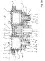
- FIG. 1 In the representation of the ball mill according to the invention in FIG. 1 is an eruption of a housing 8 to see on which the support device 1 is rotatably mounted about a center axis 15.
- the ball mill further has a drive 17 for the carrier device.
- a motor drives a V-belt 19, which is engaged with the bottom disk 6 of the carrier device 1.
- the ball mill has a drive 27 for receiving devices 2, via which the receiving devices can be set in rotation about the planet or receiving axes 25.
- a toothed belt 21 transmits via correspondingly dimensioned pinion 23, the rotation of the support device on the receiving devices 2, wherein an over- or reduction can take place.
- in the context of the invention in principle also the possibility of reversing the direction of rotation.
- the support device 1 further comprises a cover plate 4 and a shell element 7.
- the upper boundary plane 10 for rotating parts of the ball mill is substantially covered by the cover 4 together with the upper limit of Grilling vessel 5 defined. Only the co-rotating lever elements 70 protrude beyond the plane 10 for attachment of the cover 52 to the grinding bowl 51.
- the locking means according to the invention can be used in particular with such a compactly constructed ball mill, in which the grinding vessel 5 is sunk in the receiving device 2 and in the carrier device 1.
- the locking means according to the invention are not limited to an application in such a mill, but can also develop their above-mentioned advantages, if no such recessed arrangement of the grinding jars is selected.
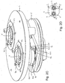
- FIG. 2A has the cover 4 openings 45, through which the receiving devices 2 are sunk into the interior of the support device 1 in.
- the grinding vessel 5 is also sunk through the opening 45 in the cover 4 in the interior of the support device 1, wherein the grinding vessel 5 is inserted into the receiving device 2. Furthermore, the bottom plate 6 can be seen.
- FIGS. 2A and 2 B the two recording devices 2 are shown in different angular position. In practice, however, the two receiving devices 2 will usually be aligned the same, as shown in the Figures 2C, 2D and 2E is shown.
- a receiving device 2 is provided with a first bearing device 31 and a second bearing device 32 about a receiving axis 25 rotatably mounted in the carrier device 1.
- the upper bearing device 32 is sunk in the cover 4.
- the lower bearing device 31 is arranged in the bottom disk 6.
- the carrier device 1 itself is rotatably mounted about the center axis 15 via a third bearing device 33 and a fourth bearing device 34.
- the third bearing device 33 is arranged in the bottom disk 6.
- the thickness of the bottom disk 6 is greater than the height of the bearing device 33.
- the third bearing device 33 is therefore embedded in the bottom plate 6 together with the first bearing device 31.
- the receiving device 2 is formed in one piece and comprises an upper region forming a space 2a for receiving the grinding vessel 5 and a lower region forming an axle extension around the receiving axis.
- the upper, a space for receiving the grinding vessel 5 forming area is cup-shaped and has an inner contour which is adapted to the outer shape of the grinding vessel 5.
- This upper, an upwardly open cavity 2a for receiving the grinding vessel 5 forming region has a bottom and an adjoining the bottom annular side wall. The side wall is substantially completely closed.
- the grinding vessel 5 is surrounded by the receiving device 2 almost completely annular and it is in particular a substantially full-surface contact of the lateral surface 55 of the grinding vessel 5 with the inner wall of the receiving device 2 allows.
- the axle extension 30 of the receiving device 2 is hollow in the embodiment shown.
- the axle extension 30 can, as in the FIG. 2B shown one Have through hole.
- the invention is also to be realized with an axle extension 30, which comprises a blind hole.
- An ejector pin 28 for the grinding vessel 5 is held in the hollow axle extension 30 of the receiving device 2.
- the ejector pin 28 is biased upon insertion of the grinding vessel 5 by means of a spring, not shown.
- the ejector pin 28 has a recess 35 for receiving axis 25 towards shoulder 35, which defines an upper seat for the spring.
- a lower seat for the spring is formed by the lower lens of the receiving device 2, which is connected to the hollow axle extension 30 of the receiving device 2.
- the grinding vessel 5 When inserting the grinding vessel 5 in the receiving device 2 of the ejector pin 28 is pressed through the bottom of the grinding vessel 5 down, into the hollow axle extension of the receiving device 2. In this position, the grinding vessel 5 is secured in the receiving device 2 by latching. The spring is compressed. If the attachment of the grinding vessel 5.in the receiving device 2 is released, the spring relaxes and pushes the ejector pin 28 upwards so that it moves the grinding vessel 5 upwards.
- Each receiving device 2 has two diametrically opposite actuating pins 93, which cooperate with a respective detent ball 92.
- the detent balls 92 in turn interact with the grinding vessel 5.
- the actuating pins 93 have a lower end 94.
- the carrier device has to secure the Actuating pin 93 a, in this example with the bottom plate 6 and thus with the support device 1 rotatably connected stop plate 91 as a securing means.
- the actuating pin 93 are locked and can not be moved from its position shown, in which the detent ball 92 is held in engagement with the grinding vessel, since the lower end 94 is blocked by the stop plate 91.
- passage openings 96 are provided in the stop plate 91.
- the two receiving devices 2 are shown in an operable position.
- the receiving device 2 is in such an orientation in the carrier device that the lower end 94 of the actuating element 93 can enter the passage opening 96 when the actuating element 93 is moved downward.
- the actuating element 93 can be pressed down by the operator, as explained below, so that the latching means can assume an open position. It can be seen that this double security function is achieved, namely on the one hand, the actuators 93 are only betägigbar when the mill is in the operating position and on the other hand, the rotation of the support device is prevented when at least one actuator 93 is in its release position.
- FIG. 3D shows a plan view of a receiving device 2.
- the receiving device 2 shown on the outside, an upper edge and, shown in the center, a space 2a for receiving the grinding vessel 5.
- the actuating pin 93 can be seen for the locking means.
- the receiving device is longitudinal in cross section along the section line AA Figure 3D shown.
- the receiving device 2 comprises pins 22 as guide means, which engage in an axial guide groove 550 of the grinding vessel 5, when this is used in angular correct position in the receiving device 2.
- the receiving device further comprises the ejector pin 28. Not shown is the spring which biases the ejector pin axially when the grinding vessel 5 is fully inserted into the receiving device 2 and pushes the ejector pin 28 down with its bottom and thus biases the spring.
- FIG. 3B is a section along the section line BB with respect to Figure 3D shown in which the locking means are shown in cross section.
- the receiving device 2 has cooling ribs on the outside and inside in order to facilitate the removal of heat from the millbase via the grinding bowl wall and the receiving device.
- the receiving device 2 comprises actuating pin 93 and locking body 92.
- the actuating pin 93 have a first Receiving portion 932 for the locking body 92, and a holding portion 935 in the form of a locking bolt with which the locking body can be in contact. Whether at least a part of the detent body 92 engages in the first receptacle 932, or whether the detent body in contact with the.
- Holding portion 935 of the actuating element 93 is dependent on the axial position of the actuating element, in particular whether the actuating element 93 is in its closed position or in its open position.
- the holding area or locking pin 935 is axially displaceably mounted and guided in a plain bearing bush 936.
- the actuating pins 93 are in the illustrated embodiment rotationally symmetrical pins, which are mounted axially displaceably in guide channels 97 in the outer peripheral region of the receiving device 2.
- the actuating pins 93 have an upper portion, which is designed as a kind of push button 98. If a force is exerted on the bolt by the operator via this push button, the actuating pin can be displaced axially.
- An actuating pin 93 further has a lower portion, which comprises means complementary to the locking body, so that by actuation of the bolt 93, the displacement of the detent ball 92 for locking or for opening the locking of the grinding vessel 5 in the receiving device 2 can be effected.
- the actuating pin 93 has in its lower area next to the holding area 935 the first receiving area 932 for the detent ball 92.
- the pushbutton-like designed end 98 of the actuating bolt 93 opposite end is formed by the stop surface 94.
- the invention is not limited to an axially movable actuator.
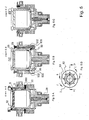
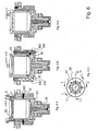
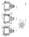
- FIGS. 4 . 5 . 6 and 7 show FIG. 3 Corresponding representations of the receiving device 2 in different stages of the insertion of the grinding bowl 5 in the receiving device 2.
- About the guide means and the locking means is the grinding vessel 5 in contact with the receiving device. 2
- FIG. 4 the grinding vessel 5 is shown in its immersed position with respect to the receiving device 2.
- the grinding bowl 5 is inserted into the receiving device 2 and rotated about its longitudinal axis until the grooves 550 of the grinding bowl 51 "find" with the setscrews 22 of the receiving device 2, so that on further lowering of the grinding vessel 5 in the receiving device 2, the set screws 22 in can slide the grooves 550.
- Locking balls 92 and actuating pin 93 of the locking means are in the closed position.
- the locking balls 92 are in contact with holding portions 935 of the actuating pin 93.
- the receiving device 2 has in the design according to the figures depending on two actuating pins 93 and locking balls, which are arranged diametrically opposite in the receiving device 2. In the context of the invention, however, more or less locking means may be provided.
- the grinding vessel 5 has on the grinding bowl 51 second receiving areas 95 for the ratchet body.
- the second receiving areas comprise recesses for receiving at least a portion of the detent body 92.
- Such a recess may be designed as a circumferential groove outside the grinding vessel.
- the grinding bowl 51 as a second receiving area on an annular groove in the outer circumferential surface of the grinding bowl 51. Locking balls 92 can engage in this annular groove in order to lock the grinding jar 5 axially in the receiving device 2.
- the second receiving areas are designed as calottes 95.
- the calottes 95 are positioned by the correct orientation of the grinding vessel 5 in the receiving device 2 via the guide groove 550 and the threaded pins 22 so that they can engage around the locking ball 92 upon actuation of the bolt 93 and correspondingly far lowering the grinding bowl 5 in its target position ( FIG. 4B ).
- FIG. 5 shows a comparison with the representation of the immersion position of the grinding vessel in FIG. 4 slightly further lowered position of the grinding vessel 5 in the receiving device 2, namely the intermediate position.
- the guide pins 22 are in engagement with the guide groove 550.
- the locking means with actuating pin 93 and detent ball 92 are in the closed position, wherein the grinding vessel 5 is lowered so far that it is prevented by further contact with the detent ball 92 on further lowering.
- the detent ball 92 is prevented from coming in contact with the holding portion 935 of the actuating bolt 93 at a radial displacement with respect to the receiving axis 25 to the outside.
- the detent ball 92 therefore protrudes into the space 2a of the receiving device 2 for receiving the grinding vessel 5, so that the grinding vessel 5 is blocked by the detent ball 92 in its axial position.
- Another lowering of the grinding vessel 5 in the receiving device 2 from the intermediate position is out in the embodiment shown only possible when the operator actuates the actuating pin 93 in the insertion direction of the grinding vessel 5, that is, in the present case, presses down.
- FIG. 6 the arrangement is shown in a setting with latching means opened as described above.
- FIG. 6B shows the pressed down actuating pin 93 which is shaped so that it allows the deflection of the detent ball 92 and thus the further insertion of the grinding vessel 5 in the open position of the locking means.
- the operator can exert a force, for example on the cover 52 and thus move the entire grinding vessel 5 further down into the receiving device 2.
- a force for example on the cover 52 and thus move the entire grinding vessel 5 further down into the receiving device 2.
- FIG. 7 the latched target position of the grinding vessel 5 is shown in the receiving device 2.
- the guide pin 22 has its reaches upper end position in the guide groove 550.
- the ejector pin 28 is opposite to in the FIGS. 4 . 5 and 6 shown, not fully inserted positions of the grinding vessel 5 down in his recording driven.
- FIG. 7B it can be seen that the detent ball 92 has moved into the dome 95, so that the actuating pin 93 could return to its closed position.
- springs which axially bias the actuating pins.
- helical compression springs can be used for the axial bias of the actuating pin 93, as well as for and the ejector pin 28, for example.
- the detent ball 92 and the actuating pin 93 When inserting the grinding vessel 5 in the receiving device 2 so move the grinding vessel 5, the detent ball 92 and the actuating pin 93.
- the grinding jar 5 moves from top to bottom.
- the detent ball 92 moves from the inside to the outside and back inwards with respect to the receiving axis.
- the actuating pin 93 moves from top to bottom and back up.
- the movements of the grinding vessel 5, the detent ball 92 and the actuating pin 93 correspond due to the running in response to the movements transfer of the detent ball from one component to another with each other.
- the detent ball 92 is handed over, as it were, from the holding region 935 of the actuating bolt 93 to the first receiving region 932, and further from the first receiving region 932 of the actuating bolt 93 to the second receiving region 95 of the grinding vessel 5, the detent ball 92 again comes into contact with the holding portion 935 of the actuating bolt 93.
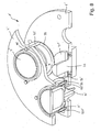
- FIG. 8 shows a schematic diagram of another embodiment of the planetary ball mill according to the invention with four receiving devices, each with a grinding jar 5 'of which only two, of which the left cut, are shown. Corresponding components in relation to the FIGS. 1 to 7 are provided with the same reference numerals and apostrophe.
- the mill has a non-integer speed ratio between sun and planetary rotation.
- the securing device comprises a locking ring 99 revolving around the receiving device, which is fastened to the locking bolt 935 ', which in this embodiment, however, is axially separated from the upper part of the actuating bolt 93'.
- the locking pin 935 ' rotates as in the Fig. 1 to 7 shown mill with the recording device with.
- the upper part of the actuating bolt 93 'in this embodiment is not as in FIG Fig. 1 to 7 co-rotating with the receiving device, ie the planetary rotation, but attached to the support device 1 '.
- the locking pin 935 ' is actuated indirectly by means of the locking ring 99.
- the stop element 91 ' is attached as a circular ring element at the center postbolt 26 rotationally fixed to the device housing and overlaps in a large angular range with the locking ring 99 to lock it in general, as in the rear grinding vessel 5'.
- the stop element 91 ' has an opening in the form of a lateral recess 96', which eliminates the blocking and the movement of the locking ring 99 and thus the actuating elements 93 'and the locking pin 935' in a certain angular position (left grinding vessel 5 ') of the support device. 1 releases.
Landscapes
- Engineering & Computer Science (AREA)
- Food Science & Technology (AREA)
- Crushing And Grinding (AREA)
Claims (22)
- Broyeur à boulets, en particulier broyeur à boulets planétaire ou centrifuge à l'échelle de laboratoire, comprenant
un bâti (8),
un dispositif de support (1) qui est monté sur le bâti (8) avec possibilité de rotation autour d'un axe central (15),
au moins un dispositif de réception (2) pour au moins un récipient de broyage (5), qui est monté tournant par rapport au dispositif de support (1), avec possibilité de rotation autour d'un axe de réception (25), et est entraîné par ledit dispositif de support autour de l'axe central (15),
un moyen d'entraînement (17) pour le dispositif de support (1),
un moyen d'entraînement (27) pour le dispositif de réception (2),
au moins un récipient de broyage (5) qui peut être chargé avec des boulets de broyage et comprend un bol de broyage (51) et un couvercle (2) destiné à fermer le bol de façon démontable,
le récipient de broyage (5) étant maintenu dans une position finale dans le dispositif de réception (2), lorsqu'il est engagé complètement dans ce dernier, et
le dispositif de réception (2) et le récipient de broyage (5) présentant des moyens d'encliquetage (92, 93, 932, 935, 95) complémentaires, en vue de la fixation démontable du récipient de broyage (5) dans la position finale dans le dispositif de réception (2). - Broyeur à boulets selon la revendication 1, caractérisé par le fait que les moyens d'encliquetage (92, 93, 932, 935, 95) agissent directement entre le récipient de broyage (5) et le dispositif de réception (2).
- Broyeur à boulets selon une des revendications précédentes, caractérisé par le fait que
les moyens d'encliquetage (92, 93, 932, 935, 95) agissent directement entre le bol de broyage (51) et le dispositif de réception (2). - Broyeur à boulets selon une des revendications précédentes, caractérisé par le fait que
les moyens d'encliquetage (92, 93, 932, 935, 95) sont conçus pour établir une liaison par obstacle entre le récipient de broyage (5) et le dispositif de réception (2). - Broyeur à boulets selon une des revendications précédentes, caractérisé par le fait que
les moyens d'encliquetage (92, 93, 932, 935, 95) comportent au moins un corps d'encliquetage (92), en particulier au moins une bille d'encliquetage. - Broyeur à boulets selon une des revendications précédentes, caractérisé par le fait que
le corps d'encliquetage (92) est monté dans le dispositif de réception (2), avec possibilité de déplacement radial par rapport à l'axe de réception (25), et peut occuper une position fermée et une position ouverte, le corps d'encliquetage (92),
lorsqu'il est en position fermée, étant placé dans une partie du dispositif de réception (2) qui forme un espace (2a) destiné à recevoir le récipient de broyage (5), de sorte qu'un déplacement axial du récipient de broyage dans le dispositif de réception est empêché lorsque le récipient de broyage (5) entre en contact avec le corps d'encliquetage (92) en position fermée, et
lorsqu'il est en position ouverte, étant placé à l'extérieur de la zone du dispositif de réception (2) qui forme un espace (2a) destiné à recevoir le récipient de broyage (5). - Broyeur à boulets selon une des revendications précédentes, caractérisé par le fait que
le récipient de broyage peut être placé dans le dispositif de réception à partir d'une position d'engagement pour arriver dans une position finale, en passant par une position intermédiaire, sachant que
dans la position d'engagement, au moins une partie, notamment la partie inférieur, du récipient de broyage (5) pénètre dans le dispositif de réception (2),
dans la position intermédiaire, le récipient de broyage (5) est bloqué en déplacement axial dans le dispositif de réception (2), lorsque ledit récipient (5) entre en contact avec le corps d'encliquetage (92) qui est en position fermée, et
dans la position finale, le récipient de broyage (5) est verrouillé dans le dispositif de réception (2) par les moyens d'encliquetage (92, 93, 932, 935, 95). - Broyeur à boulets selon une des revendications précédentes, caractérisé par le fait que
les moyens d'encliquetage (92, 93, 932, 935, 95) comprennent au moins un élément d'actionnement (93) destiné à amener le corps d'encliquetage (92) de sa position ouverte à sa position fermée et de sa position fermée à sa position ouverte,
l'élément d'actionnement (93) ayant
une position de verrouillage dans laquelle le corps d'encliquetage (92) est en position fermée, et
une position de libération dans laquelle le corps d'encliquetage (92) est en position ouverte,
le déplacement de l'élément d'actionnement (93) de sa position de verrouillage à sa position de libération,
en réponse à l'arrivée du corps d'encliquetage (92) dans la position ouverte,
permettant d'amener le récipient de broyage (5) de sa position d'engagement à sa position finale, notamment en dépassant sa position intermédiaire, et de sa position finale à sa position d'engagement. - Broyeur à boulets selon une des revendications précédentes, caractérisé par le fait que
l'élément d'actionnement (93) présente une première zone de réception (932) qui est destinée à recevoir au moins une partie d'un corps d'encliquetage (92) et avec laquelle le corps d'encliquetage (92) entre en prise lorsqu'il est en position ouverte. - Broyeur à boulets selon une des revendications précédentes, caractérisé par le fait
qu'il comprend au moins un axe d'arrêt (935) avec lequel le corps d'encliquetage (92) est en contact lorsqu'il est en position fermée. - Broyeur à boulets selon une des revendications précédentes, caractérisé par le fait que
l'élément d'actionnement (93) est tenu avec possibilité de déplacement axial dans le dispositif de réception (2), sachant que
dans la position de verrouillage, l'axe d'arrêt (935) maintient le corps d'encliquetage (92) dans une zone du dispositif de réception (2) qui forme un espace (2a) destiné à recevoir le récipient de broyage (5), et
dans la position de libération, la première zone de réception (932) reçoit au moins une partie du corps d'encliquetage (92), de sorte que le corps d'encliquetage est placé à l'extérieur de la zone du dispositif de réception (2) qui forme un espace (2a) pour recevoir le récipient de broyage (5). - Broyeur à boulets selon une des revendications précédentes, caractérisé par le fait que
les moyens d'encliquetage (92, 93, 932, 935, 95) comportent au moins une deuxième zone de réception (95) sur le récipient de broyage (5), qui est destinée à recevoir au moins une pante du corps d'encliquetage (92) et avec laquelle le corps d'encliquetage (92) peut être en prise lorsqu'il est en position fermée, lorsque le récipient de broyage (5) est engagé complètement dans le dispositif de réception (2). - Broyeur à boulets selon une des revendications précédentes, caractérisé par le fait que
la deuxième zone de réception (95) est placée sur le bol de broyage (51). - Broyeur à boulets selon une des revendications précédentes, caractérisé par le fait que
la deuxième zone de réception (95) comprend au moins un creux dans la paroi extérieure (55) du récipient de broyage (5). - Broyeur à boulets selon une des revendications précédentes, caractérisé par le fait que
la deuxième zone de réception (95) comprend une gorge, s'étendant sur le pourtour du récipient de broyage (5), et/ou une calotte. - Broyeur à boulets selon une des revendications précédentes, caractérisé par le fait
qu'il comporte au moins un moyen d'arrêt (91, 94, 96) qui maintient les moyens d'encliquetage (92, 93, 932, 935, 95) dans la position fermée, dans la majeure partie de la plage angulaire de la rotation, ledit broyeur définissant une position de service dans laquelle le moyen d'arrêt (91, 94, 96) est déverrouillé, de sorte que dans la position de service l'élément d'actionnement (93) peut être déplacé de sa position de verrouillage dans sa position de libération. - Broyeur à boulets selon une des revendications précédentes, caractérisé par le fait que
dans le dispositif de support (1), le dispositif de réception (2) occupe une position de service angulaire par rapport à l'axe de réception (25), dans laquelle l'élément d'actionnement (93) peut être déplacé de sa position de verrouillage dans sa position de libération, et
le dispositif de support (1) comprend au moins un moyen d'arrêt (91, 94, 96) pour bloquer les moyens d'encliquetage (92, 93, 932, 935, 95) dans la position fermée,
les moyens d'arrêt (91, 94, 96) étant déverrouillés lorsque le dispositif de réception (2) est placé dans sa position de service. - Broyeur à boulets selon une des revendications précédentes, caractérisé par le fait que
les moyens d'arrêt (91, 94, 96) comportent un élément de butée (91,91') qui
est lié de façon solidaire en rotation au dispositif de support (1),
forme une butée pour l'élément d'actionnement (93), au nombre d'au moins un, des moyens d'encliquetage,
l'élément de butée (91) présentant au moins une ouverture de passage (96) pour l'élément d'actionnement (93), au nombre d'au moins un, des moyens d'encliquetage, et
le dispositif de réception (2) occupant la position de service dans le dispositif de support (1) lorsque l'élément d'actionnement (93) des moyens d'encliquetage est aligné avec l'ouverture de passage (96) de l'élément de butée. - Broyeur à boulets selon une des revendications précédentes, caractérisé par le fait que
le dispositif de réception (2) comprend au moins un dispositif d'éjection (28, 29) destiné à éjecter le récipient de broyage (5) du dispositif de réception (2),
le dispositif d'éjection (28, 29), en réponse au déplacement de l'élément d'actionnement (93) de sa position de verrouillage dans sa position de libération, amenant le récipient de broyage (5) de sa position finale au moins dans sa position d'engagement. - Broyeur à boulets selon une des revendications précédentes, caractérisé par le fait que
le dispositif d'éjection (28, 29) comprend au moins un éjecteur (28) qui est positionné dans un moyen de guidage (29) de manière telle que l'éjecteur occupe une première position jusqu'à ce que le récipient de broyage (5) entre en contact avec l'éjecteur (28) lors de sa mise en place dans le dispositif de réception (2), et occupe une deuxième position lorsque le récipient de broyage (5) est placé dans sa position finale dans le dispositif de réception (2). - Broyeur à boulets selon une des revendications précédentes, caractérisé par le fait que
le dispositif d'éjection (28, 29) comprend au moins un ressort, en particulier un ressort en spirale, pour mettre l'éjecteur sous précontrainte dans sa deuxième position. - Broyeur à boulets selon une des revendications précédentes, caractérisé par le fait que
le récipient de broyage et le dispositif d'éjection présentent des moyens d'entraînement (71, 21; 500, 22, 550; 92, 93, 95) complémentaires, destinés à entraîner le récipient de broyage lors de la rotation du dispositif de réception autour de l'axe de réception, les moyens d'entraînement établissent un contact par complémentarité de forme entre la paroi latérale du récipient de broyage et le dispositif de réception, lorsque le récipient de broyage est placé dans le dispositif de réception.
Applications Claiming Priority (3)
| Application Number | Priority Date | Filing Date | Title |
|---|---|---|---|
| DE202005015896U DE202005015896U1 (de) | 2005-10-07 | 2005-10-07 | Kugelmühle mit Rastmittel |
| DE200620007799 DE202006007799U1 (de) | 2006-05-13 | 2006-05-13 | Kugelmühle mit Mitnahmemitteln für eine formschlüssige Verbindung zwischen Mahlgefäß und Aufnahmevorrichtung |
| PCT/EP2006/009643 WO2007042203A1 (fr) | 2005-10-07 | 2006-10-05 | Broyeur a boulets pourvu de moyens d'encliquetage |
Publications (2)
| Publication Number | Publication Date |
|---|---|
| EP1933985A1 EP1933985A1 (fr) | 2008-06-25 |
| EP1933985B1 true EP1933985B1 (fr) | 2009-12-16 |
Family
ID=37528445
Family Applications (1)
| Application Number | Title | Priority Date | Filing Date |
|---|---|---|---|
| EP06828804A Ceased EP1933985B1 (fr) | 2005-10-07 | 2006-10-05 | Broyeur a boulets pourvu de moyens d'encliquetage |
Country Status (3)
| Country | Link |
|---|---|
| EP (1) | EP1933985B1 (fr) |
| DE (1) | DE502006005687D1 (fr) |
| WO (1) | WO2007042203A1 (fr) |
Cited By (2)
| Publication number | Priority date | Publication date | Assignee | Title |
|---|---|---|---|---|
| DE102010044254A1 (de) | 2010-09-02 | 2012-03-08 | Fritsch Gmbh | Kugelmühle mit Querverspannung des Mahlbechers |
| WO2012041982A1 (fr) | 2010-10-01 | 2012-04-05 | Lo Insa | Dispositif pour couper des cheveux |
Families Citing this family (8)
| Publication number | Priority date | Publication date | Assignee | Title |
|---|---|---|---|---|
| DE102012007530B4 (de) | 2012-04-17 | 2017-05-11 | Fritsch Gmbh | Mahlgefäß für eine Labormühle |
| DE102012009984B4 (de) | 2012-05-22 | 2026-01-22 | Fritsch Gmbh | Laborkugelmühle |
| DE102012009982B4 (de) | 2012-05-22 | 2026-01-15 | Fritsch Gmbh | Laborkugelmühle |
| DE102012009987B4 (de) | 2012-05-22 | 2023-02-23 | Fritsch Gmbh | Laborkugelmühle |
| DE102012009985B4 (de) | 2012-05-22 | 2026-01-29 | Fritsch Gmbh | Laborkugelmühle |
| DE102012009983B4 (de) | 2012-05-22 | 2026-01-15 | Fritsch Gmbh | Kugelmühle mit automatisch verstellbarer Ausgleichsmasse |
| US10518269B2 (en) * | 2017-10-13 | 2019-12-31 | SPEX SamplePrep, LLC | Grinding mill with securing frame |
| DE102019126162B4 (de) * | 2019-01-16 | 2025-03-13 | Retsch Gmbh | Kugelmühle |
Family Cites Families (5)
| Publication number | Priority date | Publication date | Assignee | Title |
|---|---|---|---|---|
| GB746059A (en) * | 1953-08-14 | 1956-03-07 | Frank Limb O B E | Improvements in and relating to ball and like mills |
| DE1151718B (de) * | 1960-03-25 | 1963-07-18 | Netzsch Maschinenfabrik | Zentrifugal-Kugelmuehle |
| DE19712905C2 (de) * | 1997-03-27 | 2003-11-06 | Fritsch Gmbh Laborgeraetebau | Planetenkugelmühle |
| JP4006177B2 (ja) * | 2000-12-05 | 2007-11-14 | 住友重機械テクノフォート株式会社 | 大容量竪型ボールミル |
| AU2002362152A1 (en) * | 2002-09-24 | 2004-04-19 | Vladimir Georgievich Kochnev | Planetary mill |
-
2006
- 2006-10-05 WO PCT/EP2006/009643 patent/WO2007042203A1/fr not_active Ceased
- 2006-10-05 EP EP06828804A patent/EP1933985B1/fr not_active Ceased
- 2006-10-05 DE DE502006005687T patent/DE502006005687D1/de active Active
Cited By (3)
| Publication number | Priority date | Publication date | Assignee | Title |
|---|---|---|---|---|
| DE102010044254A1 (de) | 2010-09-02 | 2012-03-08 | Fritsch Gmbh | Kugelmühle mit Querverspannung des Mahlbechers |
| DE102010044254B4 (de) * | 2010-09-02 | 2017-08-10 | Fritsch Gmbh | Kugelmühle mit Querverspannung des Mahlbechers |
| WO2012041982A1 (fr) | 2010-10-01 | 2012-04-05 | Lo Insa | Dispositif pour couper des cheveux |
Also Published As
| Publication number | Publication date |
|---|---|
| WO2007042203A1 (fr) | 2007-04-19 |
| DE502006005687D1 (de) | 2010-01-28 |
| EP1933985A1 (fr) | 2008-06-25 |
Similar Documents
| Publication | Publication Date | Title |
|---|---|---|
| EP3021974B1 (fr) | Centrifugeuse | |
| EP0401548B1 (fr) | Dispositif à outil de vissage | |
| EP3012027B1 (fr) | Ensemble d'embrayage actionné par la force centrifuge pour une centrifugeuse de laboratoire | |
| EP1725437B1 (fr) | Dispositif pour empecher la rotation de l'arbre de direction d'un vehicule automobile | |
| EP0253181A2 (fr) | Mécanisme de fixation d'outils en forme de disque sur une broche de machine-outil électrique portative | |
| DE102006047480B4 (de) | Kugelmühle mit Mitnahmemitteln für eine formschlüssige Verbindung zwischen Mahlgefäß und Aufnahmevorrichtung | |
| EP1933985B1 (fr) | Broyeur a boulets pourvu de moyens d'encliquetage | |
| EP3634834A1 (fr) | Palier libre, mécanisme de direction et système de direction | |
| DE102006047479B4 (de) | Kugelmühle und Mahlgefäß mit eigenem Verbindungsmittel für Becher und Deckel | |
| EP0343347B1 (fr) | Tourelle porte-outil | |
| EP0275441B1 (fr) | Dispositif de serrage | |
| DE69907311T2 (de) | Axial entkuppelndes Schloss für ein Schlossmechanismus eines Personenkraftwagens | |
| EP3669992B1 (fr) | Construction de connexion | |
| EP1945363B1 (fr) | Broyeur a boulets avec montage en deux points | |
| DE202005015896U1 (de) | Kugelmühle mit Rastmittel | |
| WO2008106944A2 (fr) | Dispositif de fixation d'un poinçon de presse, et procédé de fixation d'un poinçon dans une presse | |
| EP2413756B1 (fr) | Dispositif d'entraînement pour entraîner une unité de travail | |
| EP3620598B1 (fr) | Dispositif de couplage pour une ferrure de porte, système de ferrure de porte et procédé de couplage ou de découplage d'un dispositif de couplage | |
| CH688713A5 (de) | Elektrisch betriebener Hammer. | |
| DE3308916A1 (de) | Schliesszylinder | |
| DE2800396B2 (de) | Verriegelungsvorrichtung, insbesondere für Koksofentüren | |
| DE102016111965A1 (de) | Umschalteinrichtung | |
| DE69832917T2 (de) | Mikrowellenschalter | |
| DE202006007799U1 (de) | Kugelmühle mit Mitnahmemitteln für eine formschlüssige Verbindung zwischen Mahlgefäß und Aufnahmevorrichtung | |
| DE19837147C5 (de) | Spannfutter für Werkzeugmaschinen |
Legal Events
| Date | Code | Title | Description |
|---|---|---|---|
| PUAI | Public reference made under article 153(3) epc to a published international application that has entered the european phase |
Free format text: ORIGINAL CODE: 0009012 |
|
| 17P | Request for examination filed |
Effective date: 20080331 |
|
| AK | Designated contracting states |
Kind code of ref document: A1 Designated state(s): DE FR |
|
| RBV | Designated contracting states (corrected) |
Designated state(s): DE FR |
|
| GRAC | Information related to communication of intention to grant a patent modified |
Free format text: ORIGINAL CODE: EPIDOSCIGR1 |
|
| GRAP | Despatch of communication of intention to grant a patent |
Free format text: ORIGINAL CODE: EPIDOSNIGR1 |
|
| DAX | Request for extension of the european patent (deleted) | ||
| GRAS | Grant fee paid |
Free format text: ORIGINAL CODE: EPIDOSNIGR3 |
|
| GRAA | (expected) grant |
Free format text: ORIGINAL CODE: 0009210 |
|
| AK | Designated contracting states |
Kind code of ref document: B1 Designated state(s): DE FR |
|
| REF | Corresponds to: |
Ref document number: 502006005687 Country of ref document: DE Date of ref document: 20100128 Kind code of ref document: P |
|
| PLBE | No opposition filed within time limit |
Free format text: ORIGINAL CODE: 0009261 |
|
| STAA | Information on the status of an ep patent application or granted ep patent |
Free format text: STATUS: NO OPPOSITION FILED WITHIN TIME LIMIT |
|
| 26N | No opposition filed |
Effective date: 20100917 |
|
| REG | Reference to a national code |
Ref country code: FR Ref legal event code: PLFP Year of fee payment: 10 |
|
| REG | Reference to a national code |
Ref country code: FR Ref legal event code: PLFP Year of fee payment: 11 |
|
| REG | Reference to a national code |
Ref country code: FR Ref legal event code: PLFP Year of fee payment: 12 |
|
| REG | Reference to a national code |
Ref country code: FR Ref legal event code: PLFP Year of fee payment: 13 |
|
| PGFP | Annual fee paid to national office [announced via postgrant information from national office to epo] |
Ref country code: DE Payment date: 20181030 Year of fee payment: 13 |
|
| PGFP | Annual fee paid to national office [announced via postgrant information from national office to epo] |
Ref country code: FR Payment date: 20181023 Year of fee payment: 13 |
|
| REG | Reference to a national code |
Ref country code: DE Ref legal event code: R119 Ref document number: 502006005687 Country of ref document: DE |
|
| PG25 | Lapsed in a contracting state [announced via postgrant information from national office to epo] |
Ref country code: DE Free format text: LAPSE BECAUSE OF NON-PAYMENT OF DUE FEES Effective date: 20200501 |
|
| PG25 | Lapsed in a contracting state [announced via postgrant information from national office to epo] |
Ref country code: FR Free format text: LAPSE BECAUSE OF NON-PAYMENT OF DUE FEES Effective date: 20191031 |