EP1934523B1 - Chambre de combustion et turbine à gaz - Google Patents
Chambre de combustion et turbine à gaz Download PDFInfo
- Publication number
- EP1934523B1 EP1934523B1 EP06793722.7A EP06793722A EP1934523B1 EP 1934523 B1 EP1934523 B1 EP 1934523B1 EP 06793722 A EP06793722 A EP 06793722A EP 1934523 B1 EP1934523 B1 EP 1934523B1
- Authority
- EP
- European Patent Office
- Prior art keywords
- combustion chamber
- burner
- wall
- insert
- burner insert
- Prior art date
- Legal status (The legal status is an assumption and is not a legal conclusion. Google has not performed a legal analysis and makes no representation as to the accuracy of the status listed.)
- Ceased
Links
Images

Classifications
-
- F—MECHANICAL ENGINEERING; LIGHTING; HEATING; WEAPONS; BLASTING
- F23—COMBUSTION APPARATUS; COMBUSTION PROCESSES
- F23R—GENERATING COMBUSTION PRODUCTS OF HIGH PRESSURE OR HIGH VELOCITY, e.g. GAS-TURBINE COMBUSTION CHAMBERS
- F23R3/00—Continuous combustion chambers using liquid or gaseous fuel
- F23R3/42—Continuous combustion chambers using liquid or gaseous fuel characterised by the arrangement or form of the flame tubes or combustion chambers
- F23R3/60—Support structures; Attaching or mounting means
-
- F—MECHANICAL ENGINEERING; LIGHTING; HEATING; WEAPONS; BLASTING
- F23—COMBUSTION APPARATUS; COMBUSTION PROCESSES
- F23D—BURNERS
- F23D14/00—Burners for combustion of a gas, e.g. of a gas stored under pressure as a liquid
- F23D14/46—Details
- F23D14/72—Safety devices, e.g. operative in case of failure of gas supply
- F23D14/78—Cooling burner parts
-
- F—MECHANICAL ENGINEERING; LIGHTING; HEATING; WEAPONS; BLASTING
- F23—COMBUSTION APPARATUS; COMBUSTION PROCESSES
- F23R—GENERATING COMBUSTION PRODUCTS OF HIGH PRESSURE OR HIGH VELOCITY, e.g. GAS-TURBINE COMBUSTION CHAMBERS
- F23R3/00—Continuous combustion chambers using liquid or gaseous fuel
- F23R3/02—Continuous combustion chambers using liquid or gaseous fuel characterised by the air-flow or gas-flow configuration
- F23R3/04—Air inlet arrangements
- F23R3/10—Air inlet arrangements for primary air
Definitions
- the present invention relates to a combustion chamber, in particular a combustion chamber for a gas turbine plant, comprising a burner and a burner insert surrounding the burner while leaving a gap open towards the interior of the combustion chamber.
- a gas turbine plant with such a combustion chamber.
- a gas turbine plant is a turbomachine that essentially comprises a compressor section, a turbine section and a burner section with one or more combustion chambers arranged between the compressor section and the turbine section.
- ambient air is sucked through the compressor and compressed to an elevated pressure.
- the compressed air is supplied to the burner section, where it is burned by means of a burner in a combustion chamber.
- the combustion exhaust gas which is hot due to combustion and is under high pressure, is finally supplied as a working medium to the turbine section, where it relaxes and cools under power, converting the energy of the working fluid into mechanical work.
- the energy converted in the turbine section in mechanical work serves on the one hand to drive the compressor and on the other hand to drive a consumer, for example a generator for generating electricity.
- premix combustion In modern gas turbine plants mostly the so-called premix combustion is used.
- premix combustion the fuel is first mixed with an oxidant, typically air, before the mixture is ignited.
- pilot fuel mass flow In the premix combustion often comes a separate fuel mass flow used, which is used to stabilize the flame use and is referred to as pilot fuel mass flow.
- the pilot fuel mass flow becomes fed via a separate from the main fuel supply system. It serves to protect the flame from instabilities due to the thermoacoustic behavior of the combustion.
- pilot mixed premix combustion Premix combustion using a pilot gas stream is also called pilot mixed premix combustion.
- piloted premix combustion the NO x emission of the combustion system depends on the amount of pilot mass fuel flow supplied. The lower the pilot fuel mass flow, the lower the NO x emission.
- a combustion chamber with a burner designed for piloted premix combustion is known, for example, in US Pat US 2005/0016178 A1 described.
- the burner is surrounded by a burner insert, wherein between the burner insert and the burner to the combustion chamber interior open annular gap is present.
- the combustion chamber insert comprises a carrier as well as a burner insert wall arranged upstream of the carrier towards the interior of the combustion chamber and simultaneously forming the combustion chamber wall in the region of the burner.
- a cooling air channel is formed between the burner insert wall and the carrier, which is supplied from the outside of the combustion chamber with cooling air. This cooling air channel is sealed against the annular gap between the burner insert and the burner.
- At the end of the burner insert wall remote from the burner there is also an opening to the interior of the combustion chamber, via which the cooling air flowing through the cooling air passage is discharged into the combustion chamber interior.
- Another object of the present invention is to provide an improved gas turbine plant.
- the first object is achieved by a combustion chamber with a burner and a burner insert surrounding the burner according to claim 1.
- the second object by a gas turbine plant according to claim 8.
- a combustion chamber according to the invention is equipped with a burner and a burner insert surrounding the burner.
- the burner may be suitable in particular for pilot-operated premix combustion. Between the burner and the burner insert, a gap open towards the interior of the combustion chamber is left.
- the combustion chamber insert comprises a carrier and a carrier insert wall which precedes the carrier toward the combustion chamber interior and between which a flow channel communicating with a cooling fluid source is formed. The flow channel opens into the gap between the burner and the burner insert and is otherwise sealed against the combustion chamber interior.
- the inventive design of the combustion chamber makes it possible to cool the burner insert wall, which also forms the combustion chamber wall usually used cooling fluid in the gap between the burner and the burner insert. In this way, an introduction of cooling fluid, usually cooling air, take place directly at the burner outlet.
- cooling fluid usually cooling air
- By introducing cooling fluid in the immediate vicinity of the burner outlet into the combustion chamber it is possible to achieve an improvement in the thermoacoustic behavior of the combustion exhaust gases in the combustion chamber. Due to the improved thermoacoustic behavior can be made a reduction in the pilot gas quantity, resulting in a reduction in NO x emissions follows.
- the burner insert wall is usually fastened by means of a rib engaging in a groove of the carrier rib in the region of the flow channel on the carrier.
- the rib in this case has at least one passage opening enabling the passage of cooling fluid, for example at least one bore.
- the carrier has cooling fluid channels, which communicate directly or indirectly with the cooling fluid source and open into the flow channel.
- cooling fluid channels which communicate directly or indirectly with the cooling fluid source and open into the flow channel.
- the combustion chamber according to the invention can in particular be designed as an axially symmetrical annular combustion chamber with a number of burners distributed around the axis of symmetry and at least one burner insert.
- the burner insert wall of a burner insert has at least one abutting edge on which it adjoins a abutting edge of an adjacent burner insert or on a combustion chamber wall.
- a seal is then present, which seals the burner insert wall against the combustion chamber interior. In this way you can prevent that from flowing through the flow channel flowing cooling fluid instead through the gap between the burner and the burner insert flows through gaps between adjacent burner inserts or between a burner insert and the combustion chamber wall into the combustion chamber.
- a gas turbine plant according to the invention is equipped with a combustion chamber according to the invention.
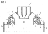
- FIG. 1 A section of a combustion chamber according to the invention is in FIG. 1 shown in a sectional view.
- a burner 1 a burner insert 3, which annularly surrounds the burner 1, and to recognize a part of the combustion chamber wall 5.
- the combustion chamber is arranged in a Brennschplenum 4 and extends annularly around a turbine shaft (not shown).
- the burner 1 is inserted into a receptacle of the burner insert 3.
- the burner insert 3 adjoins the combustion chamber wall 5 and closes off the combustion chamber.
- the burner insert 3 comprises a carrier 7, which is designed as a grooved ring: In this run one or more annular grooves around the burner 1 around, can be supplied to the burner 1 by the cooling air. For better clarity, the grooves are not shown.
- the grooved ring 7 upstream of the combustion chamber interior 2 towards a burner insert wall 9 is present, which at the same time represents the burner 1 surrounding the end wall of the combustion chamber 1.
- the burner insert wall 9 has a circumferential web 23, with which the wall is inserted into a groove 21 of the grooved ring 7 and held there. Through bores 11, 15 in the grooved ring 7, the side of the burner insert wall 9 facing away from the combustion chamber interior 2 can be blown with cooling air in order to effect impingement cooling.
- FIG. 3 The grooved ring 7, the burner insert wall 9 and a section of the combustion chamber wall 5 and a section of the burner 1 are in FIG. 3 shown enlarged. Between the U-ring 7 and the burner insert wall 9, a flow channel 13 is formed, which is supplied from the Brennschplenum 4 fro cooling air as cooling fluid. In this sense, combustor plenum 4 may be considered as a source of cooling fluid.
- the flow paths of the cooling air are in FIG. 3 indicated by arrows.
- a seal 19 is arranged between the abutting edge and the combustion chamber wall 5.
- the seal is preferably flexible in order to compensate for thermal expansions. It can e.g. be made as metal.
- the gap between the burner 1 and the burner insert 3 is sealed by a serving as a seal piston ring 31.
- the cooling air used for cooling the burner insert wall 9 flows into the combustion chamber directly next to the burner outlet 33 through an annular gap 29 and is fed to the combustion process. This improves the thermoacoustic behavior of the combustion chamber and thereby enables a reduction of the supplied pilot fuel quantity and thus to a reduction of the NO x emissions.
- FIG. 2 A top view of the burner insert 3 and the burner 1 seen from the combustion chamber interior is in FIG. 2 shown. Arrows indicate the flow paths of the cooling air along the combustion chamber insert wall 9.
- combustion chamber In the center of the burner insert 3, the burner wall 33 surrounding the burner opening 27 can be seen. Between the burner insert wall 9 and the combustion wall 27 is the annular gap 29 through which the cooling air used for cooling the burner insert wall 9 flows into the combustion chamber interior 2.
- combustion chamber In the FIG. 2 illustrated combustion chamber is an annular combustion chamber, which is arranged axially symmetrically around a turbine rotor.
- the radially outer combustion chamber wall 5A and the radially inner combustion chamber wall 5B can be seen.
- seals 19A and 19B are provided, which seal the flow channel of the combustion chamber insert 3 against the combustion chamber interior 2.
- a separate burner insert 3 is present for each burner 1.
- the burner inserts 3 adjoin one another in the circumferential direction of the combustion chamber. Gaps between opposing abutting edges 17C, 17D of burner insert walls 9 of adjacent burner inserts 3 are also sealed with seals 19C, 19D against the combustion chamber interior to prevent leakage of cooling air through these gaps.
- seals 19C, 19D against the combustion chamber interior to prevent leakage of cooling air through these gaps.
- the air mass flow supplied to the combustion chamber interior 2 through the flow channel 13 corresponds to only a few percent of the air mass flow fed through the burner 1.
- the air mass flow supplied through the flow channel 13 is less than about 5% of the air mass flow supplied by the burner 1.
- combustion chamber can also be designed as an approximately cylindrical combustion chamber with at least one burner and at least one burner insert on the end face of the cylinder.
Landscapes
- Engineering & Computer Science (AREA)
- Chemical & Material Sciences (AREA)
- Combustion & Propulsion (AREA)
- Mechanical Engineering (AREA)
- General Engineering & Computer Science (AREA)
Claims (8)
- Chambre de combustion, comprenant un brûleur ( 1 ) et un insert ( 3 ) de brûleur, qui entoure le brûleur ( 1 ) en laissant un intervalle ( 29 ) ouvert en direction de l'intérieur ( 2 ) de la chambre de combustion et qui comprend un support ( 7 ) et une paroi ( 9 ) d'insert de brûleur posée avant le support ( 7 ) par rapport à l'intérieur ( 2 ) de la chambre de combustion, un canal ( 13 ) d'écoulement en communication avec une source ( 4 ) de fluide de refroidissement étant formé entre le support ( 7 ) et la paroi ( 9 ) de l'insert de brûleur, caractérisée en ce que le canal ( 13 ) d'écoulement débouche dans l'intervalle ( 29 ) entre le brûleur ( 1 ) et l'insert ( 3 ) de brûleur et pour le reste est rendu étanche vis-à-vis de l'intérieur ( 2 ) de la chambre de combustion.
- Chambre de combustion suivant la revendication 1, caractérisée en ce que la paroi ( 9 ) de l'insert de brûleur est fixée au support ( 7 ) au moyen d'une nervure ( 23 ) pénétrant dans la région du canal ( 13 ) d'écoulement dans une rainure ( 21 ) du support ( 7 ) et la nervure ( 23 ) a au moins une ouverture ( 25 ) de passage permettant un passage du fluide de refroidissement.
- Chambre de combustion suivant la revendication 2, caractérisée en ce que la au moins une ouverture de passage est conformée sous la forme d'un trou ( 25 ) dans la nervure.
- Chambre de combustion suivant l'une des revendications précédentes,
caractérisée en ce que le support ( 7 ) a des canaux ( 11, 15 ) pour du fluide de refroidissement, qui sont en communication indirectement ou directement avec la source ( 4 ) de fluide de refroidissement et qui débouchent dans le canal ( 13 ) d'écoulement. - Chambre de combustion suivant l'une des revendications précédentes,
caractérisée en ce qu'il y a, entre le support ( 7 ) et le brûleur ( 1 ), un joint ( 31 ) rendant l'intervalle ( 29 ) étanche vis-à-vis d'un plénum de la chambre de combustion. - Chambre de combustion suivant l'une des revendications précédentes,
caractérisée par sa conformation sous la forme d'une chambre de combustion annulaire à symétrie axiale, ayant un certain nombre de brûleurs ( 1 ) répartis autour de l'axe de symétrie et au moins un insert ( 3 ) de brûleur. - Chambre de combustion suivant l'une des revendications précédentes,
caractérisée en ce que la paroi ( 9 ) d'un insert ( 3 ) de brûleur a au moins un rebord ( 17 ), où la paroi ( 9 ) d'insert de brûleur est voisine d'un rebord ( 17 ) d'un insert ( 3 ) de brûleur voisin ou d'une paroi ( 5 ) de la chambre de combustion, et en ce que, entre les rebords ( 17 ) d'insert ( 3 ) de brûleur voisins et/ou entre le rebord ( 17 ) et la paroi ( 5 ) de la chambre de combustion, il y a un joint ( 19 ), qui rend étanche la paroi ( 9 ) de l'insert de brûleur vis-à-vis de l'intérieur ( 2 ) de la chambre de combustion. - Installation de turbine à gaz ayant une chambre de combustion suivant l'une des revendications précédentes.
Priority Applications (1)
| Application Number | Priority Date | Filing Date | Title |
|---|---|---|---|
| EP06793722.7A EP1934523B1 (fr) | 2005-09-27 | 2006-09-21 | Chambre de combustion et turbine à gaz |
Applications Claiming Priority (3)
| Application Number | Priority Date | Filing Date | Title |
|---|---|---|---|
| EP05021085A EP1767855A1 (fr) | 2005-09-27 | 2005-09-27 | Chambre de combustion et turbine à gaz |
| PCT/EP2006/066602 WO2007036486A1 (fr) | 2005-09-27 | 2006-09-21 | Chambre a combustion et installation de turbine a gaz |
| EP06793722.7A EP1934523B1 (fr) | 2005-09-27 | 2006-09-21 | Chambre de combustion et turbine à gaz |
Publications (2)
| Publication Number | Publication Date |
|---|---|
| EP1934523A1 EP1934523A1 (fr) | 2008-06-25 |
| EP1934523B1 true EP1934523B1 (fr) | 2014-10-29 |
Family
ID=35636740
Family Applications (2)
| Application Number | Title | Priority Date | Filing Date |
|---|---|---|---|
| EP05021085A Withdrawn EP1767855A1 (fr) | 2005-09-27 | 2005-09-27 | Chambre de combustion et turbine à gaz |
| EP06793722.7A Ceased EP1934523B1 (fr) | 2005-09-27 | 2006-09-21 | Chambre de combustion et turbine à gaz |
Family Applications Before (1)
| Application Number | Title | Priority Date | Filing Date |
|---|---|---|---|
| EP05021085A Withdrawn EP1767855A1 (fr) | 2005-09-27 | 2005-09-27 | Chambre de combustion et turbine à gaz |
Country Status (3)
| Country | Link |
|---|---|
| US (1) | US8393161B2 (fr) |
| EP (2) | EP1767855A1 (fr) |
| WO (1) | WO2007036486A1 (fr) |
Cited By (1)
| Publication number | Priority date | Publication date | Assignee | Title |
|---|---|---|---|---|
| DE102019217983A1 (de) * | 2019-11-21 | 2021-05-27 | Siemens Aktiengesellschaft | Brennereinsatz, Verfahren zu dessen Herstellung sowie Verwendung eines solchen Brennereinsatzes |
Families Citing this family (8)
| Publication number | Priority date | Publication date | Assignee | Title |
|---|---|---|---|---|
| US9121609B2 (en) | 2008-10-14 | 2015-09-01 | General Electric Company | Method and apparatus for introducing diluent flow into a combustor |
| US20100089022A1 (en) * | 2008-10-14 | 2010-04-15 | General Electric Company | Method and apparatus of fuel nozzle diluent introduction |
| EP2182285A1 (fr) | 2008-10-29 | 2010-05-05 | Siemens Aktiengesellschaft | Pièce du brûleur pour une chambre de combustion d'une turbine à gaz et turbine à gaz |
| EP2354661B1 (fr) * | 2010-02-04 | 2018-04-11 | General Electric Technology GmbH | Dispositif de combustion pour turbine à gaz |
| GB201107090D0 (en) * | 2011-04-28 | 2011-06-08 | Rolls Royce Plc | A head part of an annular combustion chamber |
| EP2522909B1 (fr) * | 2011-05-12 | 2015-04-08 | Siemens Aktiengesellschaft | Turbine à gaz avec brûleur et procédé de réglage d'une turbine à gaz dotée d'un tel brûleur |
| FR3019216B1 (fr) * | 2014-03-31 | 2018-08-10 | Safran Aircraft Engines | Deflecteur de fond de chambre de combustion d'une turbomachine comportant des rainures sur le pourtour d'une ouverture centrale |
| US11774093B2 (en) * | 2020-04-08 | 2023-10-03 | General Electric Company | Burner cooling structures |
Family Cites Families (7)
| Publication number | Priority date | Publication date | Assignee | Title |
|---|---|---|---|---|
| US4322945A (en) * | 1980-04-02 | 1982-04-06 | United Technologies Corporation | Fuel nozzle guide heat shield for a gas turbine engine |
| DE19508111A1 (de) * | 1995-03-08 | 1996-09-12 | Bmw Rolls Royce Gmbh | Hitzeschild-Anordnung für eine Gasturbinen-Brennkammer |
| ITMI991207A1 (it) * | 1999-05-31 | 2000-12-01 | Nuovo Pignone Spa | Camera di combustione per turbine a gas |
| US6314739B1 (en) * | 2000-01-13 | 2001-11-13 | General Electric Company | Brazeless combustor dome assembly |
| US6546733B2 (en) * | 2001-06-28 | 2003-04-15 | General Electric Company | Methods and systems for cooling gas turbine engine combustors |
| US6581386B2 (en) * | 2001-09-29 | 2003-06-24 | General Electric Company | Threaded combustor baffle |
| US7080515B2 (en) | 2002-12-23 | 2006-07-25 | Siemens Westinghouse Power Corporation | Gas turbine can annular combustor |
-
2005
- 2005-09-27 EP EP05021085A patent/EP1767855A1/fr not_active Withdrawn
-
2006
- 2006-09-21 US US11/992,530 patent/US8393161B2/en not_active Expired - Fee Related
- 2006-09-21 WO PCT/EP2006/066602 patent/WO2007036486A1/fr not_active Ceased
- 2006-09-21 EP EP06793722.7A patent/EP1934523B1/fr not_active Ceased
Cited By (2)
| Publication number | Priority date | Publication date | Assignee | Title |
|---|---|---|---|---|
| DE102019217983A1 (de) * | 2019-11-21 | 2021-05-27 | Siemens Aktiengesellschaft | Brennereinsatz, Verfahren zu dessen Herstellung sowie Verwendung eines solchen Brennereinsatzes |
| WO2021099055A1 (fr) | 2019-11-21 | 2021-05-27 | Siemens Energy Global GmbH & Co. KG | Pièce rapportée de brûleur, procédé de fabrication associé et utilisation dudit type de pièce rapportée de brûleur |
Also Published As
| Publication number | Publication date |
|---|---|
| EP1767855A1 (fr) | 2007-03-28 |
| US8393161B2 (en) | 2013-03-12 |
| US20090133378A1 (en) | 2009-05-28 |
| EP1934523A1 (fr) | 2008-06-25 |
| WO2007036486A1 (fr) | 2007-04-05 |
Similar Documents
| Publication | Publication Date | Title |
|---|---|---|
| DE69818376T2 (de) | Gasturbinenbrennkammer | |
| DE102011000587B4 (de) | Systeme und Verfahren zur Zufuhr von Hochdruckluft zum Kopfende einer Brennkammer | |
| EP2808611B1 (fr) | Injecteur pour l'introduction d'un mélange air-carburant dans une chambre de combustion | |
| DE102016106491A1 (de) | Brennstoffdüsenanordnung mit einer Pilotdüse | |
| DE102014117621A1 (de) | Brennstoffinjektor mit Vormisch-Pilotdüse | |
| CH701961A2 (de) | Strömungsmaschine. | |
| DE102015120448A1 (de) | Vormischbrennstoffdüsenanordnung | |
| DE112012006144T5 (de) | Brennkammeranordnung einer Turbomaschine | |
| CH710574B1 (de) | System und Verfahren zur Nutzung von Kühlluft in einem Brenner. | |
| DE102015122927A1 (de) | Pilotdüse in einer Gasturbinenbrennkammer | |
| DE102015121653A1 (de) | Pilotdüse in einer Gasturbinenbrennkammer | |
| CH701454B1 (de) | Brenner mit einem Strömungskonditionierer. | |
| CH701950B1 (de) | Brennstoffdüse und Verfahren zum Betreiben der Brennstoffdüse. | |
| DE102015112767A1 (de) | Brennstoffinjektoranordnungen in Verbrennungsturbinen | |
| DE102015122924A1 (de) | Pilotdüse in einer Gasturbinenbrennkammer | |
| EP2340397A1 (fr) | Insert de brûleur pour une chambre de combustion d'une turbine à gaz et turbine à gaz | |
| CH702556A2 (de) | Düse und Verfahren zur Brennstoffzufuhr durch eine mit gegenläufigem Drall arbeitende Düse. | |
| DE102015113146A1 (de) | Systeme und Vorrichtungen im Zusammenhang mit Gasturbinenbrennkammern | |
| DE112013007579T5 (de) | Flüssigbrennstoffpatrone für eine Brennstoffdüse | |
| DE102015119749A1 (de) | Vormischbrennstoffdüsenanordnung | |
| EP1934523B1 (fr) | Chambre de combustion et turbine à gaz | |
| DE112014004655B4 (de) | Brennstoffeinspritzvorrichtung für eine Gasturbine | |
| DE2116429A1 (de) | Brennkammer fur Gasturbinenmaschinen | |
| DE102019219686B4 (de) | Gasturbinenbrennkammer und gasturbine | |
| EP2236932A1 (fr) | Procédé de fonctionnement d'un brûleur et brûleur, notamment pour une turbine à gaz |
Legal Events
| Date | Code | Title | Description |
|---|---|---|---|
| PUAI | Public reference made under article 153(3) epc to a published international application that has entered the european phase |
Free format text: ORIGINAL CODE: 0009012 |
|
| 17P | Request for examination filed |
Effective date: 20070820 |
|
| AK | Designated contracting states |
Kind code of ref document: A1 Designated state(s): CH DE GB IT LI |
|
| RBV | Designated contracting states (corrected) |
Designated state(s): CH DE GB IT LI |
|
| DAX | Request for extension of the european patent (deleted) | ||
| RAP1 | Party data changed (applicant data changed or rights of an application transferred) |
Owner name: SIEMENS AKTIENGESELLSCHAFT |
|
| GRAP | Despatch of communication of intention to grant a patent |
Free format text: ORIGINAL CODE: EPIDOSNIGR1 |
|
| INTG | Intention to grant announced |
Effective date: 20140512 |
|
| GRAS | Grant fee paid |
Free format text: ORIGINAL CODE: EPIDOSNIGR3 |
|
| GRAA | (expected) grant |
Free format text: ORIGINAL CODE: 0009210 |
|
| AK | Designated contracting states |
Kind code of ref document: B1 Designated state(s): CH DE GB IT LI |
|
| REG | Reference to a national code |
Ref country code: GB Ref legal event code: FG4D Free format text: NOT ENGLISH |
|
| REG | Reference to a national code |
Ref country code: CH Ref legal event code: NV Representative=s name: SIEMENS SCHWEIZ AG, CH Ref country code: CH Ref legal event code: EP |
|
| REG | Reference to a national code |
Ref country code: DE Ref legal event code: R096 Ref document number: 502006014048 Country of ref document: DE Effective date: 20141204 |
|
| REG | Reference to a national code |
Ref country code: DE Ref legal event code: R097 Ref document number: 502006014048 Country of ref document: DE |
|
| PLBE | No opposition filed within time limit |
Free format text: ORIGINAL CODE: 0009261 |
|
| STAA | Information on the status of an ep patent application or granted ep patent |
Free format text: STATUS: NO OPPOSITION FILED WITHIN TIME LIMIT |
|
| 26N | No opposition filed |
Effective date: 20150730 |
|
| PGFP | Annual fee paid to national office [announced via postgrant information from national office to epo] |
Ref country code: GB Payment date: 20150909 Year of fee payment: 10 |
|
| PGFP | Annual fee paid to national office [announced via postgrant information from national office to epo] |
Ref country code: IT Payment date: 20150924 Year of fee payment: 10 |
|
| PGFP | Annual fee paid to national office [announced via postgrant information from national office to epo] |
Ref country code: DE Payment date: 20151120 Year of fee payment: 10 Ref country code: CH Payment date: 20151202 Year of fee payment: 10 |
|
| REG | Reference to a national code |
Ref country code: DE Ref legal event code: R119 Ref document number: 502006014048 Country of ref document: DE |
|
| REG | Reference to a national code |
Ref country code: CH Ref legal event code: PL |
|
| GBPC | Gb: european patent ceased through non-payment of renewal fee |
Effective date: 20160921 |
|
| PG25 | Lapsed in a contracting state [announced via postgrant information from national office to epo] |
Ref country code: GB Free format text: LAPSE BECAUSE OF NON-PAYMENT OF DUE FEES Effective date: 20160921 Ref country code: CH Free format text: LAPSE BECAUSE OF NON-PAYMENT OF DUE FEES Effective date: 20160930 Ref country code: LI Free format text: LAPSE BECAUSE OF NON-PAYMENT OF DUE FEES Effective date: 20160930 Ref country code: DE Free format text: LAPSE BECAUSE OF NON-PAYMENT OF DUE FEES Effective date: 20170401 |
|
| PG25 | Lapsed in a contracting state [announced via postgrant information from national office to epo] |
Ref country code: IT Free format text: LAPSE BECAUSE OF NON-PAYMENT OF DUE FEES Effective date: 20160921 |